
The Heat Treat Doctor® has returned to offer sage advice to Heat Treat Today readers and to answer your questions about heat treating, brazing, sintering, and other types of thermal treatments as well as questions on metallurgy, equipment, and process-related issues.
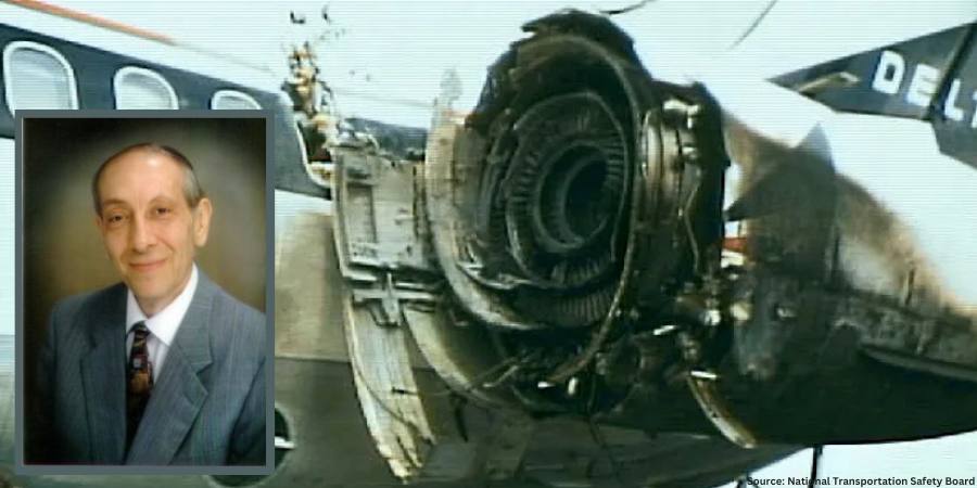
Product failures (Figure 1) can often be traced to deficiencies in design, materials, manufacturing, quality, maintenance, service-related factors, and human error to name a few. Examples of failures include misalignment, buckling, excessive distortion, cracking, fracture, creep, fatigue, shock, wear, corrosion, and literally hundreds of other mechanisms. Let’s learn more.

Source: National Transportation Safety Board
Source: The HERRING GROUP, Inc.
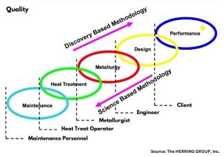
Whatever the source, it is important to recognize that it is next to impossible to separate the product from the process. Performance, design (properties and material), metallurgy (microstructure), heat treatment (process and equipment), and maintenance are all interconnected (Figure 2).
When considering ways to prevent failures from occurring, one must determine the factors involved and whether they acted alone or in combination with one another. Ask questions such as, “Which of the various failure modes were the most important contributors?” and “Was the design robust enough?” and “Were the safety factors properly chosen to meet the application rigors imposed in service?” Having a solid engineering design coupled with understanding the application, loading, and design requirements is key to avoiding failures. If failures do happen, we must know what contributed to them.
Let’s review a few of the more common failure modes.
Fracture Types on a Macroscopic Scale
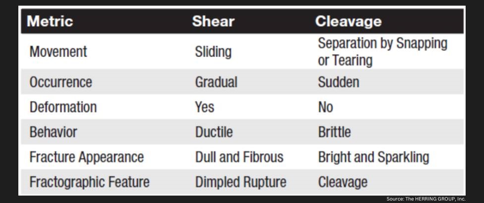
Applied loads may be unidirectional or multi-directional in nature and occur singularly or in combination. The result is a macroscopic stress state comprised of normal stress (perpendicular to the surface) and/or shear stress (parallel to the surface). In combination with the other load conditions, the result is one of four primary modes of fracture: dimpled rupture (aka microvoid coalescence), cleavage, decohesive rupture, and fatigue.
Virtually all engineering metals are polycrystalline. As a result, the two basic modes of deformation/fracture (under single loading) are shear and cleavage (Table 1). The shear mechanism, which occurs by sliding along specific crystallographic planes, is the basis for the macroscopic modes of elastic and plastic deformation. The cleavage mechanism occurs very suddenly via a splitting action of the planes with very little deformation involved. Both of these micro mechanisms primarily result in transgranular (through the grains) fracture.
Fracture Types — Ductile and Brittle
Numerous factors influence whether a fracture will behave in a ductile or brittle manner (Table 2). In ductile materials, plastic deformation occurs when the shear stress exceeds the shear strength before another mode of fracture can occur, with necking typically observed before final fracture. Brittle fractures occur suddenly and exhibit very little, if any, deformation before final fracture. (The following is based on information found in Wulpi, 1985.)
Ductile fractures typically have the following characteristics:
- Considerable plastic or permanent deformation in the failure region
- Dull and fibrous fracture appearance
Brittle fractures typically have the following characteristics:

- Lack of plastic or permanent deformation in the region of the fracture
- Principal stress (or tensile stress) is perpendicular to the surface of the brittle fracture
- Characteristic markings on the fracture surface pointing back to where the fracture originated
When examined under a scanning electron microscope, fracture surfaces seldom exhibit entirely dimpled rupture (i.e. ductile fracture) or entirely cleavage (i.e. brittle fracture), although one or the other may be more prevalent. Other fracture modes include intergranular fractures, combination (quasi-cleavage) fractures and fatigue fractures.
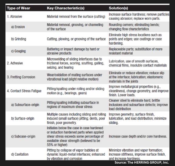
Fracture Types — Wear
Wear (Table 3) is a type of surface destruction that involves the removal of material from the surface of a component part under some form of contact produced by a form of mechanical action. Wear and corrosion are closely linked, and it is important not only to evaluate the failure but to take into consideration design and environment and have a good understanding of the service history of a component.
Fracture Types — Corrosion
Corrosion is the destruction of a component by the actions of chemical or electrochemical reactions with the service environment. The major types of corrosion include galvanic action, uniform corrosion, crevice corrosion, stress-corrosion cracking, and corrosion fatigue. The mechanisms and effects created by each of these are well documented in the literature, as in Fontana and Greene’s Corrosion Engineering (1985) and Uhlig’s Corrosion and Corrosion Control (1985). It is critical to understand that the effects of corrosion are present to some degree in every failure analysis, which is one of the reasons why protecting fracture surfaces is so critical when sending parts for failure analysis.
Source: The HERRING GROUP, Inc.

Source: The HERRING GROUP, Inc.
Source: The HERRING GROUP, Inc.
Final Thoughts
To avoid failures or their reoccurrence, it is important to document each step in the design and manufacture process (including heat treatment). In addition, careful documentation of failures if/when they occur is of critical importance as is assembling a team of individuals from different disciplines to perform a comprehensive investigation. This includes a thorough failure analysis to assist in determining the root cause (there is only one) and to avoid it from happening in the future.
References
Airline Safety. www.AirlineSafety.com. Accessed September 2024.
Fontana, M. G., and N. D. Greene. Corrosion Engineering, 3e. McGraw-Hill Book Company, 1985.
Herring, Daniel H. Atmosphere Heat Treatment, Volume Nos. 1 & 2. BNP Media, 2014/2015.
Lawn, B.R. and T. R. Wilshaw. Fracture of Brittle Solids. Cambridge University Press, 1975.
Shipley, R. J. and W. T. Becker (Eds.). ASM Handbook, Volume 11: Failure Analysis and Prevention. ASM International, 2002.
Uhlig, H. H. Corrosion and Corrosion Control. John Wiley & Sons, 1963.
Wulpi, Donald J. Understanding How Components Fail. ASM International, 1985.
About the Author

“The Heat Treat Doctor”
The HERRING GROUP, Inc.
Dan Herring has been in the industry for over 50 years and has gained vast experience in fields that include materials science, engineering, metallurgy, new product research, and many other areas. He is the author of six books and over 700 technical articles.
For more information: Contact Dan at dherring@heat-treat-doctor.com.
For more information about Dan’s books: see his page at the Heat Treat Store.