Ever wish you had a map to follow when navigating your power source? In the following Technical Tuesday article, Brian Turner, sales applications engineer at RoMan Manufacturing, Inc., charts the route that power takes from the source to the load and back again in a vacuum furnace.
This informative piece was first released in Heat Treat Today’s June 2024 Buyers’ Guide print edition.
In a vacuum furnace, the journey from the load (the material being heat treated) to the incoming power involves a complex arrangement of components that deliver, control, and monitor electrical energy. Here’s a breakdown of the path from the source to the load and back to the source of incoming power of a vacuum furnace:
Load
The material — either an item or batch of items — that is undergoing heat treatment; can be metals, ceramics, or composites.
Heating Elements
Common materials for heating elements include graphite, molybdenum, or tungsten, depending on the temperature range and application.
Electrical Feedthrough
These are used to transmit electrical power or signals through the vacuum chamber wall. They often contain insulated conductors and connectors to ensure safe transmission without leaking air into the vacuum environment.
Conductors
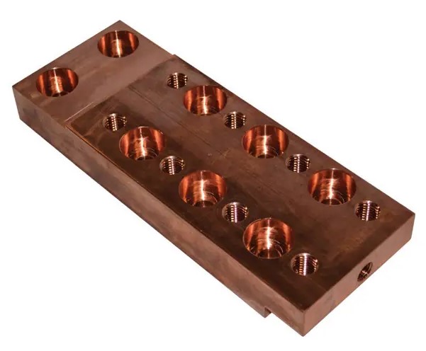
The most common methods to connect power from a vacuum power source to the furnace’s feedthrough include air-cooled cables, water-cooled cables, and copper bus bar. Power efficiency can be improved when selecting the length, size, and area between conductors. This can be achieved by close coupling the power system to the electrical feedthroughs, reducing resistance and inductive reactance, and improving the power factor.

Source: RoMan Manufacturing, Inc.
Controlled Power Distribution Systems
The furnace market today generally relies on three primary types of control power distribution systems: VRT, SCR, and IGBT. Each of these technologies employs different methods to regulate the power input to the furnace, which in turn generates the required heat.
VRT (Variable Reactance Transformer)
- The VRT controls AC voltage to the load, this is accomplished by a DC power controller that injects DC current into the reactor within the transformer.
SCR (Silicon Controlled Rectifier)
- Main control types: Phase angle control, load tap changer, zero-cross control; the firing of line voltage manages how much power is directed through the heating circuit.
- The SCR controls the AC output voltage and can be paired with a transformer to step the voltage up or down and close couple to the furnace feedthroughs.
IGBT (Insulated-Gate Bipolar Transistor)
- Balanced three-phase voltage is rectified through a bridge circuit to charge a capacitor in the DC bus. The IGBT network switches the DC bus at 1000Hz to control the AC output voltage to a Medium Frequency Direct Current (MFDC) power supply.
- MFDC power supply transforms the AC voltage to a practical level and rectifies the secondary voltage (DC) to the heating circuit.
- A line reactor on the incoming three-phase line mitigates harmonic content.
Control Systems
These systems manage the furnace’s operation, including driving the setpoint of the power system, temperature control, vacuum levels, and timing. They often consist of programmable logic controllers (PLCs), human-machine interfaces (HMIs), sensors, and other automation components.
Incoming Power
This is the origin of the furnace’s electrical energy, typically from a utility grid. It provides alternating current (AC), which is distributed and transformed within the furnace system to power all necessary components. In industrial settings, power companies usually charge for electricity based on several factors that reflect both the amount of electricity used and how it’s used. Some common charges/penalties are energy consumption (kWh), demand charges (kW), power factor penalties, and time-of-use (TOU) reactive power.
Conclusion
The careful arrangement of heating elements, electrical feedthroughs, conductors, and controlled power distribution systems allows for precise temperature control, ultimately impacting the quality of the processed material. Understanding the role of various control systems, such as VRT, SCR, IGBTs, and transformers is crucial for optimizing furnace performance and managing energy costs
About the Author:

Sales Applications Engineer
RoMan Manufacturing, Inc.
Source: RoMan Manufacturing, Inc.
Brian K. Turner has been with RoMan Manufacturing, Inc., for more than 12 years. Most of that time has been spent managing the R&D Lab. In recent years, he has taken on the role as applications engineer, working with customers and their applications.
For more information: Contact Brian at bturner@romanmfg.com.


