AEROSPACE HEAT TREAT NEWS

Distortion Analysis of Landing Gear During Oil Quench: A Case Study

Charlie Li

A thermal process modeling company used its heat treatment simulation software to explore oil quench sensitivities on the distortion of a large landing gear made of 300M, a vacuum melted low alloy steel that includes vanadium and a higher silicon composition.

DANTE Solutions, an engineering consulting and software company specializing in metallurgical process engineering and thermal/stress analyses of metal parts and components, was approached to examine local stagnant oil flow and immersion, among other sensitivities, for this critical aerospace component.

Zhichao (Charlie) Li, Ph.D., vice president of DANTE Solutions, was the lead researcher and author of this study.


Case Study

Problem Statement

Part:
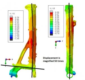
3 modes of distortion that are of concern
  • 2.5 meter tall landing gear
  • 0.25 meter main tube diameter
  • AISI 300M material

Problem:

  • Large distortions after oil quenching in the following distortion modes:
    • Bow in XY-Plane
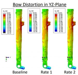
    • Bow in YZ-Plane
    • Straightness of a Blind Hole
  • All distortion modes shown in the figures make assembly of the entire structure very difficult.
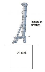
  • Immersion into the oil tank is the main focus of the distortion analysis.

Process Description

  • Part is austenitized in pit furnace at 1607°F (875°C).
  • A 45-second step is included for the removal of the landing gear from the pit furnace.
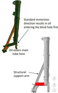
  • 75-second open-air transfer from pit furnace to oil quench tank. The landing gear is immersed into the oil with a speed of 203.2 mm/sec, with the immersion direction shown in the figure. It takes 11.885 seconds to immerse the entire gear in the oil tank.
  • The landing gear is held in the oil for 5 minutes.
  • Tempering not considered, due to negligible effects on distortion.
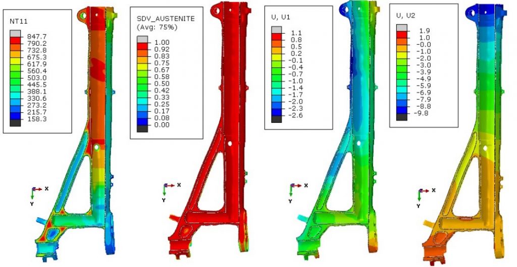
Temperature (°C), Austenite (fraction), horizontal displacement (mm), and vertical displacement (mm) at the end of the immersion process; section cut, looking inside the part.

Model Description

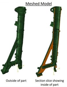
  • Model contains 281,265 nodes and 258,272 hex elements.
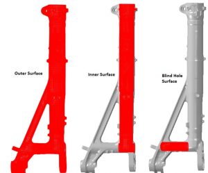
  • 3 surfaces defined for heat transfer boundary conditions.
  • Oil flow stagnation is expected inside the main tube (Inner Surface) and the blind hole.
  • Different thermal boundary conditions are applied to the outer surface and the inner surface, as shown to the right.
  • The blind hole and the inner surface have the same thermal boundary conditions in the baseline model.
  • During immersion, oil enters the blind hole first and then begins to fill up the main tube.
  • In the baseline model, the oil level rising speed inside the bore is assumed to be 20% of the landing gear immersion speed.


Modeling Approach

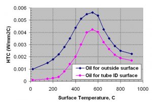
  • Define heat transfer coefficients as a function of temperature for the oil tank.
    • Thermocouples placed at various locations on a dummy landing gear, which was
      approximately the same overall dimensions and mass. Improve 300M material data in DANTE material database using dilatometry testing.
  • Improve 300M material data in DANTE material database using dilatometry testing.
  • Perform sensitivity study to determine phenomena critical to distortion modes of interest.
    • Oil flow stagnancy in blind hole during immersion: The more stagnancy, the lower the heat transfer on this surface. Baseline assumed to be the most stagnant. Two faster heat transfer rates examined.
    • Oil flow stagnancy around structural support arm: The more stagnancy, the lower the heat transfer on this surface. Baseline assumed to be least stagnant. Two slower heat transfer rates examined.
    • Oil fill rate of the main tube during immersion into the oil: The slower the oil fills up the main tube, the larger the temperature and phase transformation gradient is in the axial direction of the tube. Baseline assumed the slowest fill rate. Three faster fill rates were examined.
    • Immersion direction: Immersion direction sets up axial temperature/phase transformation gradients and also determines how the main tube is filled. The Baseline immersion direction causes oil to enter through the blind hole first and then into the main tube. Opposite immersion direction is examined, which causes oil to enter the open end of the main tube first.

Blind Hole Quench Rate Sensitivity

Figure 8. Temperature (°C) in the blind hole at the end of immersion for the three cases.
  • Heat transfer is increased in the blind hole during the
    immersion process; all other heat transfer rates
    remain the same as the baseline model during
    immersion.
  • All heat transfer rates are identical to the baseline
    after the part is fully immersed in the oil.
  • Baseline model assumes blind hole heat transfer is
    equivalent to the main tube inner diameter heat
    transfer during and after the immersion process.
  • Rate 2 has a faster heat transfer rate than the baseline.
  • Rate 1 has a faster heat transfer rate than Rate 2.
  • Figure 8 shows a significant difference in temperature between the three cases at the end of the immersion process.
  • Heat transfer rates explored in the blind hole do not contribute
    to the tilting of the blind hole.
  • Figure 9 shows that the angle of the hole is the same, regardless of the quench rate.
  • Modification of the blind hole to increase the heat transfer rate
    in the hole to help improve the straightness of the blind hole is not necessary.
  • Heat transfer rates explored in the blind hole do not contribute significantly to the bow distortion in the XYPlane or the YZ-Plane.
  • Figure 10 shows that the bow distortion is made slightly worse by increasing the heat transfer rate in the blind hole during immersion, but is not significantly worse.
  • Modification of the blind hole to increase the heat transfer rate in the hole to help improve the bow distortion is not necessary.
Figure 9
Figure 10.

Structural Beam Quench Rate Sensitivity

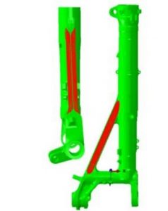
  • Reduced heat transfer of the structural arm is examined.
    • Oil flow stagnancy is assumed to reduce heat transfer rate on arm.
    • 2 slower heat transfer rates compared with baseline.
    • Baseline assumes the same heat transfer rate on the structural arm as on the main tube OD.
  • Figure to the left shows the reduced heat transfer rate surfaces of the structural arm.
  • Rate 1 is slower than Baseline.
  • Rate 2 is slower than Rate 1.
  • Figure below shows the temperature difference in the structural beam at the end of the immersion process.
  • Approximately 212°F (100°C) difference between Baseline and Rate 1
  • Approximately 392°F (200°C) difference between Baseline and Rate 2


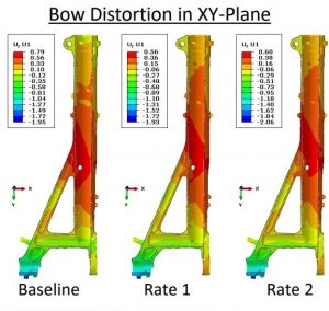
  • Bow distortion in xy-plane has a non- Distortion of Blind Hole linear response to oil stagnancy around the structural beam.
  • Rate 1 produced the least amount of bow in xy-plane.
  • Baseline produces the greatest amount of bow in xy-plane.
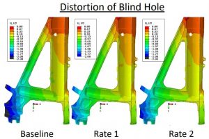
  • Distortion of blind hole has a non-linear response to oil stagnancy around the structural beam.
  • Rate 1 produced the straightest blind hole.
  • Baseline produces the greatest amount of distortion of the blind hole.
  • Bow distortion in yz-plane has no sensitivity to oil stagnancy around the structural beam.
  • The non-symmetric mass near the top of the landing gear has the most influence on the yz-plane bow distortion.
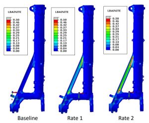
  • Figure 15 shows lower bainite phase fraction at the end of the quenching process.

    Figure 15
  • Slower heat transfer rate of the structural beam results in significantly different amounts of lower bainite.
    • The slower the heat transfer, the more lower bainite formed.
  • Increased amounts of bainite reduce bow distortion in xy-plane, but the response is non-linear.
    • Rate 2 caused slightly more distortion than Rate 1, but less distortion than the Baseline.
  • Increased amounts of bainite reduce distortion of the blind hole, but the response is non-linear.
    • Rate 2 caused slightly more distortion than Rate 1, but less distortion than the Baseline.

Oil Fill Rate in Main Tube Sensitivity

  • The rate at which the oil fills the main tube is critical to the phase transformation timings and the phases formed.
  • The immersion speed of the landing gear is 203.2 mm/sec.
  • Baseline assumes the inside of the tube fills up at 20% of this value (40.64 mm/sec).
  • Three different fill speeds were explored:
    • 50% (101.6 mm/sec)
    • 100% (203.2 mm/sec)
    • 200% (406.4 mm/sec) Assumes pressure build up forces oil up the inside of the tube.
  • Figure 16 compares temperature inside tube at end of immersion for four cases.
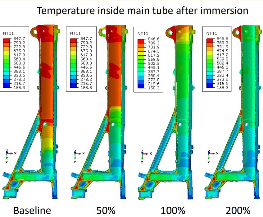
Figure 16


  • The oil fill rate of the main tube during the immersion process has a very significant effect on all three modes of distortion.
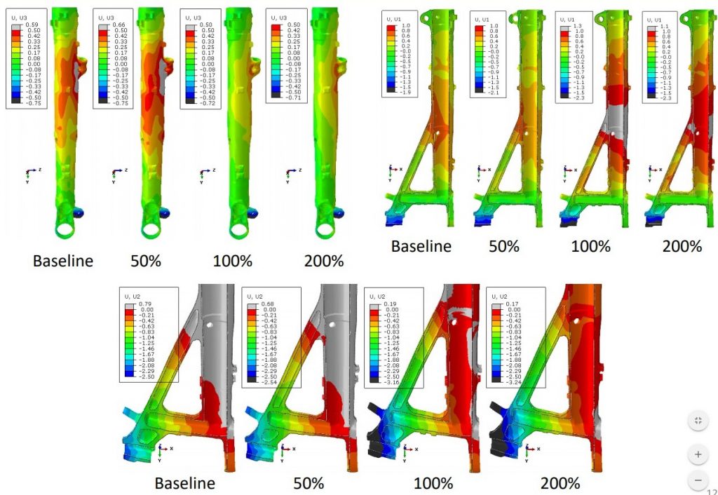
From top left clockwise

  • Bow distortion in yz-plane has a non-linear response to the fill speed (Figure 17)
    • 50% produces the worst bow
    • 100% & 200% are very similar, with 200% slightly worse
  • Bow distortion in xy-plane has a non-linear response to the fill speed (Figure 18)
    • 50% produces the least bow
    • 100% produces the worst bow
  • Straightness of the blind hole has a linear response to the fill speed (Figure 19)
    • Slowest fill speed has least distortion
    • Fastest fill speed has the worst distortion

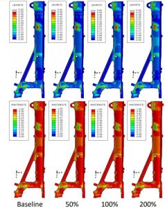
  • Difference in lower bainite was the cause for differences in distortion with respect to oil stagnancy around the structural beam previously shown.
  • Differences in distortion from the oil fill rate of the main tube are not caused by microstructural phase differences.
  • Figure 18 shows that Martensite and Lower Bainite are the same for all fill speeds.
  • Differences in distortion are caused by the transformation timing along the axis of the landing gear.


Immersion Direction Sensitivity
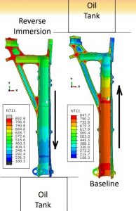
Figure 19
  • Distortion sensitivity to the immersion direction was examined.
  • Figure 19 compares temperature profile at the end of the immersion process for the two immersion directions.
  • The Baseline has oil enter the blind hole first and then fill up the tube at a rate that is 20% of the immersion speed.
    • Oil spills over the top of the tube and the tube is flooded with oil.
  • The reversed immersion has oil enter the tube first and fills at the immersion speed.
  • Figure 20

    Reversing the immersion direction also reverses the axial temperature gradient.

    • Martensite transformation starts at the open tube end when the immersion direction is reversed.
    • Martensite transformation starts by the blind hole first for the Baseline.
    • Reversing the axial phase transformation gradient can have significant effects on bow distortion and axial displacement.
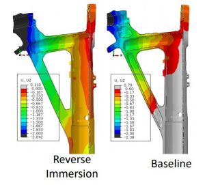
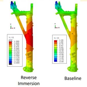
  • Figure 20 shows the vertical displacement around the blind hole for the Baseline and the Reversed Immersion.
  • Reversing the immersion direction had a very minor impact on the straightness of the blind hole.
    • Closed side of blind hole was pulled further down by reversing the immersion direction, but the closed side
      Figure 21

      was not pulled up as much.

  • Figure 21 shows the bow distortion in the XY-Plane for the Baseline and the Reversed Immersion.
  • Reversing the immersion direction has a significant effect on the bow distortion in the XY-Plane, nearly doubling it.
  • Reversing the immersion direction has no effect on the bow distortion in the YZ-Plane.


Conclusions

  • Four process parameters were evaluated for distortion sensitivities for a large landing gear component:
    • Oil stagnancy inside a blind hole, oil stagnancy around a structural support beam, oil fill rate into the main tube as the landing gear is lowered into the oil tank, and immersion direction of the landing gear.
  • Three distortion modes were evaluated:
    • Bow distortion in XY-Plane, bow distortion in YZ-Plane, and straightness of a blind hole.
  • Bow distortion in the XY-Plane IS significantly affected by oil stagnancy around structural support beam, oil fill rate up the main tube, and the immersion direction.
    • Bow distortion in the XY-Plane is mainly controlled by the behavior of the structural support beam.
  • Bow distortion in the XY-Plane IS NOT significantly affected by oil stagnancy in the blind hole.
  • Bow distortion in the YZ-Plane IS significantly affected by oil fill rate of the main tube.
    • Bow distortion in the YZ-Plane is mainly controlled by a fitting near the open end of the tube that contributes to non-symmetric mass around the main tube in that area.
  • Bow distortion in the YZ-Plane IS NOT significantly affected by oil stagnancy in the blind hole, oil stagnancy around the structural support beam, or the immersion direction.
  • Straightness of the blind hole IS significantly affected by oil stagnancy around structural support beam and the oil fill rate up the main tube .
    • Straightness of the blind hole is mainly controlled by the structural support beam behavior.
  • Straightness of the blind hole IS NOT significantly affected by oil stagnancy inside the blind hole or the immersion direction.
  • Modifications to the quenching process were made to improve the distortion response of the landing gear.
    • Modeling results were used to direct the modifications.
    • Customer considered changes proprietary and did not share.
  • Benefit of using heat treatment simulation over physical experiments to perform sensitivity studies was shown.
    • Ability to modify, and see the effects of, just one process parameter with simulation is easy.
    • Ability to modify, and see the effects of, just one process parameter with experiments is very difficult, if not impossible.
    • Cost of simulation is minimal.
    • Cost of physical experiments can be very high.


Text developed from powerpoint version. Click here to view or for more information on DANTE case studies.


Distortion Analysis of Landing Gear During Oil Quench: A Case Study Read More »

Acquisition to Launch New Metal Additive Manufacturing Business

A Cleveland, Ohio, company with metallurgy capabilities that manufactures arc welding products and systems and provides alloy brazing and soldering recently acquired a privately held supplier of custom tooling, parts, and fixtures primarily serving automotive and aerospace markets.
Christopher L. Mapes, Chairman, President and Chief Executive Officer

The acquisition by Lincoln Electric Holdings Inc. will advance the company’s automation and metal additive manufacturing capabilities and leverage its core competencies in software development and metallurgy. Baker Industries, based in Detroit, Michigan, has extensive in-house design and manufacturing capabilities, including machining, fabricating, assembly and additive manufacturing. Their operations adhere to stringent aerospace quality management standards and are AS9100D certified and Nadcap accredited.

A new metal additive manufacturing service business will launch in mid-2019 which will include the production of large-scale printed metal parts, prototypes and tooling for industrial and aerospace customers. The Baker operation, along with a new Cleveland, Ohio-based additive manufacturing development center, will provide an additive manufacturing platform to help customers improve their lead times, designs and quality in their operations.

“We are pleased to welcome Baker Industries to Lincoln Electric and to our automation portfolio’s new additive manufacturing platform,” said Christopher L. Mapes, Chairman, President and Chief Executive Officer. “Additive manufacturing is a key strategic growth area in automation, and Baker’s expertise and capabilities will assist in scaling our additive manufacturing services and expand our presence in attractive aerospace and automotive end markets.”


Main photo caption: Lincoln Electric’s new metal additive manufacturing service will launch in mid-2019 and provide large scale metal printing of industrial parts, tooling and prototypes for customers.

Acquisition to Launch New Metal Additive Manufacturing Business Read More »

Heat Treater Performs Brinell Hardness Testing with Precision for Primes

The largest subcontract heat treater of aluminum alloys in the UK, accredited to process components to Prime specifications, turned to a manufacturer of Brinell hardness testing machines to develop a more efficient testing process.

Foundrax BRINtronic automatic Brinell microscope

Alloy Heat Treatment (AHT), which serves the aerospace, automotive, energy, and other sectors, has a large number of prime customer approvals including Leonardo Helicopters, Airbus, Safran, Boeing, and BAE Systems. They are accredited to heat treat to these Prime’s specifications and often work as a trusted supplier to other companies that deal directly with them. Part of the Prime specifications dictates that Brinell hardness testing is carried out prior to releasing the components. AHT settled on the Foundrax BRINtronic automatic Brinell microscope, designed by Foundrax Engineering Products, based in Wessex, England.

“Part of the release process for aluminum alloys is that we must do conductivity and hardness testing on every job that leaves us,” said Steve Roberts, Quality Director with Alloy Heat Treatment. “As such we were looking at ways that we could gain efficiencies in this process. Using the BRINtronic from Foundrax has allowed us to gain these efficiencies.”

Brinell hardness measurements were required to be taken in areas of components where access is limited by intricate machine webbing or where the nose diameter of the microscope is restricted to approximately 30mm.

Alex Austin, Managing Director, Foundrax

“One of the problems we needed to solve with equipment selection is that the microscope must get into quite intricate places,” continued Roberts. “All the other microscopes we looked at have wide noses on them so, the design of the Foundrax scope was right up our street. We’ve used the manual Foundrax microscopes for as long as I’ve been here.”

“As the microscope automatically measures the indentation at multiple points, results are instant,” said Alex Austin, Managing Director of Foundrax. “They are recorded, and of course, the operator doesn’t have to turn the microscope 90 degrees and remeasure as he would with manual measurement. There is well over a 50% saving on measuring time.”

Foundrax BRINtronic display

“Obviously, the usability of the BRINtronic suited us,” said Roberts, “because we could get it into the places that we would struggle with using the competitor’s equipment. The process of measuring was far easier with the Foundrax BRINtronic as with the others we had to try and hold it with both hands and press buttons. They weren’t particularly well balanced either so in practice we were losing efficiencies rather than gaining them.”


Main photo caption: Steve Roberts of AHT uses the BRINtronic testing machine from Foundrax.

Heat Treater Performs Brinell Hardness Testing with Precision for Primes Read More »

Aviation Systems Manufacturer, PA Specialty Metals Group Extend Purchase Agreement

A manufacturer of power systems for aviation and other industries recently announced that it has extended its Long-Term Purchase Agreement (LTPA) with a global specialty metals company headquartered in Pittsburgh, Pennsylvania.

Warrick Matthews, Executive Vice President, Procurement and Installations Supply Chain, Rolls-Royce

Rotating disc quality specialty materials will be supplied to Rolls-Royce for their Trent engine family by Allegheny Technologies Incorporated (ATI). The LTPA extends Rolls-Royce and ATI’s agreement through 2029.

“We are very pleased to have signed another long-term agreement with ATI for disc quality nickel alloys,” said Warrick Matthews, Executive Vice President, Procurement and Installations Supply Chain, Rolls-Royce. “Rolls-Royce’s supply chain requires on-time delivery of the highest quality materials. ATI’s track record of cost, quality and delivery performance has been a key consideration in award of this contract. This new contract provides an opportunity for Rolls-Royce and ATI to further develop their relationship and to enjoy engine production and services volume growth.”

Robert S. Wetherbee, ATI’s President and Chief Executive Officer

“We are pleased to extend our long-standing relationship with Rolls-Royce, partnering with them on the development of next-generation jet engines and supporting their legacy jet engine supply chain,” said Robert S. Wetherbee, ATI’s President and Chief Executive Officer. “This agreement reliably secures Rolls-Royce’s supply of critical materials for their innovative engine portfolio for the next ten years.”

John Sims, Executive Vice President, High-Performance Materials and Components Segment

“This agreement covers the production of a wide range of critical products used to make Rolls-Royce’s next-generation jet engines as well as spare parts for in-service engines. It supports ATI’s market-leading alloy development and broad production capabilities, including our iso-thermal forging operations,” said John Sims, Executive Vice President, High-Performance Materials and Components Segment. “In recognition of ATI’s commitment to innovation, quality and operational reliability, Rolls-Royce awarded ATI a majority share of all materials covered under this LTPA. We are honored to support Rolls-Royce as they work to confidently deliver on this unprecedented aerospace ramp.”


Aviation Systems Manufacturer, PA Specialty Metals Group Extend Purchase Agreement Read More »

Heat Treating Step in Metal Filament AM Expands Applications


Source: Aerospace Manufacturing & Design


A Wisconsin-based additive manufacturing company recently came out with metal filaments encased in a binder, allowing for a two-step process of printing then heat treating to produce a safer metal 3D printing solution as well as broader use in industry applications such as

  • Biomedical innovators
  • Jet engine technology
  • Radiation shielding
  • Space exploration
  • Nuclear power


“Even with the furnace step, filament-based printing tends to be faster and requires less specialized training, making AM technologies more accessible to manufacturers who don’t have large numbers of specialists.” ~ Aerospace Manufacturing & Design

Main Image Credit/Caption: The Virtual Foundry Facebook page/”Stainless Steel 316L Filamet™ Filament. Printed using a FlashForge Creator Pro.”


Read more: “Metal Filaments Expand Additive Applications”

Heat Treating Step in Metal Filament AM Expands Applications Read More »

Heat Treat Line Expanded at Aerospace Aluminum Castings Facility

A New Hampshire-based manufacturer of sophisticated aluminum investment castings for predominantly aerospace applications recently expanded its capabilities with two electric drop bottom ovens.

Uni-Cast purchased the two furnaces for installation at its factory located in Londonderry, NH, from Pyradia Belfab, based in Saint-Hubert, Quebec. Pyradia designs and manufactures custom industrial equipment for aluminum heat treating, web converting, and dust collecting applications.

“After reviewing many quotes, we thought they were the best value out there. They make quality ovens at a competitive price. They have reasonable lead times and good engineering. I highly recommend them,” said Henri Fine, owner of Uni-Cast, which incorporates heat treating and precipitation hardening in the casting process in order to provide dimensional stability, strength, and hardness.


Main photo: Still image captured from video at Pyradia’s website.

Heat Treat Line Expanded at Aerospace Aluminum Castings Facility Read More »

Aerospace Manufacturer Expands Metal Alloy AM Capabilities, Acquires AM Services Provider

A technology-based manufacturer of aerospace and defense parts and systems recently expanded its capability to develop and produce metal alloy additive manufacturing parts for aerospace and power systems through the acquisition of AM provider which services the aerospace, defense, medical, and industrial markets.

Eileen Drake, CEO and president of Aerojet Rocketdyne

Aerojet Rocketdyne Holdings, Inc. has acquired 3D Material Technologies (3DMT) from ARC Group Worldwide, Inc., complementing Aerojet Rocketdyne’s industry-leading capabilities to develop and produce metal alloy additive manufacturing parts for aerospace propulsion and power systems. Aerojet Rocketdyne has qualified production parts for the RL10 and RS-25 liquid rocket engines and continues to develop and demonstrate the benefits of additive manufacturing for its hypersonic propulsion systems.

“The addition of 3DMT’s capacity and expertise in metal alloy additive manufacturing expands our range of products and services in the space and defense markets,” said Eileen Drake, CEO and president of Aerojet Rocketdyne. “As we look to the future, additive manufacturing will continue to play an important role in lowering costs and production timelines. This deal allows Aerojet Rocketdyne to broaden its application of this revolutionary technology. We respect the long-standing reputation for quality and customer focus that 3DMT has built in the aerospace industry and we are thrilled to welcome them to our company.”

3DMT will continue to operate with its existing workforce at its 28,000 square ft. facility located in Daytona Beach, Florida.


Main photo credit/caption: Aerojet Rocketdyne / Hot-fire test of Aerojet Rocketdyne’s ISE-100 thruster conducted at the company’s Redmond, Washington test facility

Aerospace Manufacturer Expands Metal Alloy AM Capabilities, Acquires AM Services Provider Read More »
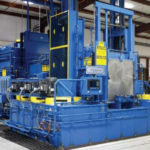
Facility Approved to Heat Treat Flight Critical, Flight Safety Configurations Invests in UBQ, UBTN Furnaces

an AFC-Holcroft UBQ furnace

A commercial heat treat company which is approved to heat treat certain flight critical and flight safety configurations for prime aerospace and helicopter companies recently invested in a new Universal Batch Quench (UBQ) furnace and a Universal Batch Temper (UBTN) annealing furnace to be operated at its plant in Fraser, Michigan.

Tracy Dougherty, VP Sales, AFC-Holcroft

“We’re excited to be a part of the continued growth and expansion of Specialty Steel Treating,” said Tracy Dougherty, Vice President of Sales at AFC-Holcroft. “The customization of these furnaces combined with state of the art controls and IoT features (Remote Diagnostics™), enable both AFC-Holcroft and Specialty Steel Treating the ability to offer superior quality, performance and continuous improvement to customers.”

Delivery of the UBTN is expected in the 2nd quarter of 2019 to the Specialty Steel Treating site on Malyn Road in Fraser, with the UBQ to follow in the 3rd quarter to the Commerce Road plant, also located in Fraser.

Facility Approved to Heat Treat Flight Critical, Flight Safety Configurations Invests in UBQ, UBTN Furnaces Read More »

Leaders in Aerospace Heat Treat LinkedIn Group: Join, Comment for a Chance to Win $100 Amazon Gift Card

Heat Treat Today recently announced the launch of the Leaders in Aerospace Heat Treat LinkedIn Group — with a special drawing for $100 Amazon gift cards. This was on the heels of releasing our inaugural Leaders in Aerospace Heat Treat monthly e-newsletter and the new Aerospace Heat Treat special print/digital edition (click here for digital).

Leaders in Aerospace Heat Treat LinkedIn Group  (click here) provides a professional-level space where heat treaters from the aerospace industry can discuss issues and ideas. Heat Treat Today will regularly provide content related to the group, keeping members current on the latest technologies, products, processes, and discussions. If you’re a heat treat leader in the aerospace industry, you should be in this group.

As a special welcome to founding members of the Leaders in Aerospace Heat Treat LinkedIn GroupHeat Treat Today is conducting a drawing for three winners, each will receive a $100 Amazon gift cards Anyone who joins the group AND comments on any of the posts during the month of April (through April 30, 2019) will be entered into the drawing.

Share the love: forward this invitation to Leaders in Aerospace Heat Treat LinkedIn Group and news about the Amazon contest to any others you feel may benefit.

Go to your LinkedIn account, sign in and search for “Leaders in Aerospace Heat Treat.” Join the group and connect with other leaders in aerospace heat treat.

For more information about the Leaders in Aerospace Heat Treat monthly e-newsletter, contact Doug Glenn at doug@heattreattoday.com.

Leaders in Aerospace Heat Treat LinkedIn Group: Join, Comment for a Chance to Win $100 Amazon Gift Card Read More »

Leaders in Aerospace Heat Treat Gain 2 More Resources for News, Discussion

It’s a busy week here at Heat Treat Today. We are announcing the launch of the Leaders in Aerospace Heat Treat LinkedIn Group — with a special drawing for $100 Amazon gift cards — as well as our inaugural Leaders in Aerospace Heat Treat monthly e-newsletter, both on the heels of the new Aerospace Heat Treat special print/digital edition (click here for digital).

Leaders in Aerospace Heat Treat LinkedIn Group  (click here) provides a professional-level space where heat treaters from the aerospace industry can discuss issues and ideas. Heat Treat Today will regularly provide content related to the group, keeping members current on the latest technologies, products, processes, and discussions. If you’re a heat treat leader in the aerospace industry, you should be in this group.

As a special welcome to founding members of the Leaders in Aerospace Heat Treat LinkedIn GroupHeat Treat Today is conducting a drawing for three winners, each will receive a $100 Amazon gift cards Anyone who joins the group AND comments on any of the posts during the month of April (through April 30, 2019) will be entered into the drawing.

Share the love: forward this invitation to Leaders in Aerospace Heat Treat LinkedIn Group and news about the Amazon contest to any others you feel may benefit.

Go to your LinkedIn account, sign in and search for “Leaders in Aerospace Heat Treat.” Join the group and connect with other leaders in aerospace heat treat.

For more information about the Leaders in Aerospace Heat Treat monthly e-newsletter, contact Doug Glenn at doug@heattreattoday.com.


Leaders in Aerospace Heat Treat Gain 2 More Resources for News, Discussion Read More »