ENERGY HEAT TREAT TECHNICAL CONTENT

Case Study: The Metallurgy Within a Reheating Furnace at DanSteel

In this article, a team of researchers describe the technical, technological, and metallurgical characteristics in heating large-sized continuous cast slabs made of low carbon microalloyed steels, using the operation at DanSteel’s rolling complex 4200 as a case study. These characteristics ensure high quality heating process of slabs used for production of high-quality heavy plates weighing up to 63 tonnes*, which are particularly in demand in the offshore wind energy and bridge construction industries.

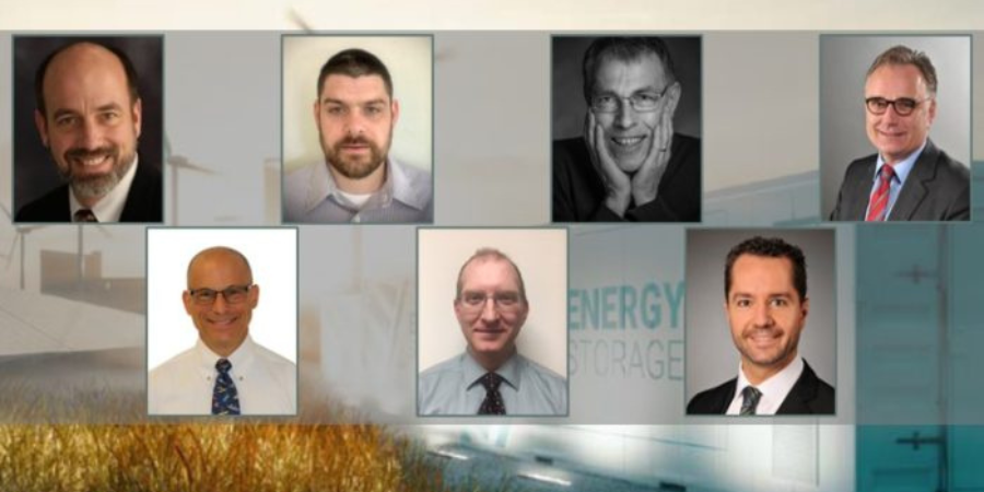
On the research team are the following: Eugene Goli-Oglu, Sergey Mezinov and Andrei Filatov, all of NLMK DanSteel, and Pietro della Putta and Jimmy Fabro of SMS group S.p.A.

This informative piece was first released in Heat Treat Today’s December 2024 Medical & Energy Heat Treat print edition.

*1 metric ton = 2204.6 pounds


The production of structural heavy plate steel is a complex multi-step process, the technological steps and operations of which have an impact on product quality and production economics. Slab reheating for rolling is one of the key process steps in the technological chain, directly linked to the quality and cost efficiency of heavy plate production process.

At DanSteel’s rolling complex 42001, continuously casted (CC) slabs are heated either in pusher type furnaces or walking beam furnaces depending on their cross section. In the case of big-size and heavy tonnage slabs with a cross-section of H x B up to 400 x 2800 mm, heating takes place in the latest generation of the SMS group walking-beam reheating furnace, installed in 2022. The main objectives of the installation of the new reheating furnace were the expansion of the product range towards the production of XXL high-quality heavy plates weighing up to 63 tonnes, which are most in demand in the offshore wind power and bridge construction industries, as well as improving the quality, economic, and environmental parameters of slab reheating process.

Figure 1. Effect of reheating temperature on particle size (a) and austenitic grain size (b) in steels (see reference 5) microalloyed simultaneously with Ti and Nb:
1 — steel with low titanium additions (Ti/N=3.24)
2 — steel with 0.02% Nb and Ti (Ti/N=3.33)
3 — steel with increased titanium content Ti/N=4.55

The aim of this article is to describe the technical, technological, and metallurgical characteristics in heating large-sized continuous cast slabs made of low carbon microalloyed steels and how this looks at the DanSteel’s rolling complex 4200.

Metallurgical Characteristics of Slab Heating

Heating of low carbon microalloyed steel slabs is one of the key technological steps in forming the optimal microstructural condition of heavy plates and their surface quality. In conjunction with microalloying, the technological parameters of heating affect such important characteristics as average grain size and uniformity of the austenitic structure, the composition of the solid solution and the type/thickness of the surface scale. In terms of heavy plate quality, the main realized task at the reheating stage is to obtain at the exit a slab with a setup temperature, the minimum temperature gradient along the thickness, width and length of the slab, optimal quality and quantitative condition of the surface scale.

The heating temperature and its uniformity are important to form a microstructure of increased uniformity. It is known2 that a fine-grained austenitic steel structure has an increased grain boundary surface per volume unit, which leads to an excess of free energy of the system, which creates a driving force that determines the subsequent grain growth. The austenitic grain grows exponentially when heated in certain temperature ranges and this grain growth tendency is always present in low carbon microalloyed steels.

Figure 2. Growth pattern of austenitic grains in steels containing various microalloying elements

There are two general mechanisms of austenitic grain growth when heating slabs: normal and abnormal growth. That is, when reaching a certain temperature, which depends on the chemical composition, the austenite grain begins to increase very rapidly in apparent diameter. Abnormal grain growth can be observed in austenitizing steels containing strong CN-forming elements. Anomalous grain growth is not observed in simple low alloyed Si-Mn steels but at heating temperatures of 2102°F–2192°F, the grain grows to very large sizes (200 μm and larger).3

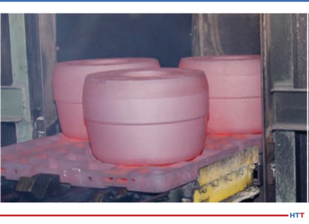
To avoid exponential grain growth of austenite during heating for rolling, dispersed particles that inhibit grain boundary migration are effectively used.4 The undissolved particles inhibit the migration of grain boundaries and thus inhibit the growth of austenitic grains. The nature of the release of particles and their effect on the average size of the austenitic grains of Ti and Nb alloyed low carbon steels is shown in Figure 1. It is important that the slab at the exit of the furnace has a given heating temperature without gradient limit deviations.

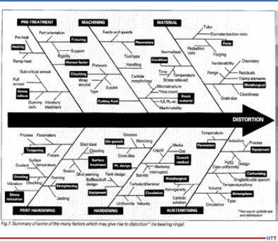
The main microalloying elements that form the optimal (fine grain) austenite structure as a result of the solid-solution effect and the formation of nitrides and carbides during slab heating are titanium, niobium, and vanadium (Figure 2).5 Titanium forms nitrides, which are stable at high temperatures in the austenitic range and allow control of the austenite grain size during heating before hot deformation. The binding of free nitrogen (which has a high affinity for carbide forming elements) by titanium has a positive effect on steel ductility and makes niobium more effective. Niobium is an effective microalloying element for refining the austenite grain during heating for rolling.6 It also has the positive effect of inhibiting austenite recrystallization during thermomechanical rolling.7

It is worth noting a number of works8, 9, 10, in which it was shown that increasing the heating temperature of V-Ti-Nb steel and the associated austenite grain enlargement does not significantly affect the size of the recrystallized grain, formed in the temperature range of complete recrystallization after repeated deformation under the same temperature and deformation conditions. This experimental result at first sight contradicts most recrystallization models11, 12, according to which the size of recrystallized austenite grain depends on the initial (before deformation) grain size and deformation temperature.

The microstructure and mechanical properties of the finished product directly depend on the heating temperature and are determined by the size and homogeneity of the austenitic grains, the stability of the austenite itself, influencing the condition of the excess phase and, consequently, the kinetics of its subsequent transformation. For timely recrystallization processes and control of dispersion hardening, it is necessary to balance the uniform fine grained austenitic microstructure and the transition of dissolved particles into solid solution when defining the heating temperature. Also, the heating temperature must be sufficiently high to fully undergo recrystallization in the interdeformation pauses.13 It should also be considered the possible negative phenomena of local and general overheating that occur when heating a slab above a certain temperature for a given steel and lead to a sharp increase in the austenitic grain size. The decreased heating temperature allows for a number of technological advantages: The possibility of reducing the pause time for cooling before the finishing step of rolling, increasing productivity of furnaces due to reduced heating time for rolling, and therefore the mill as a whole, as well as reducing the cost of the product due to saving fuel and reducing losses on scale. However, it should be remembered that some groups of low carbon steels have an optimal temperature range for heating, target temperatures above or below, which increase the heterogeneity of the microstructure. Thus, ensuring uniform heating to a given holding temperature and discharging slabs from the reheating furnace for subsequent rolling is an important technological task and contributes to the formation of austenitic microstructure and solid solution state of low carbon microalloyed steel with increased uniformity.

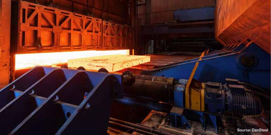
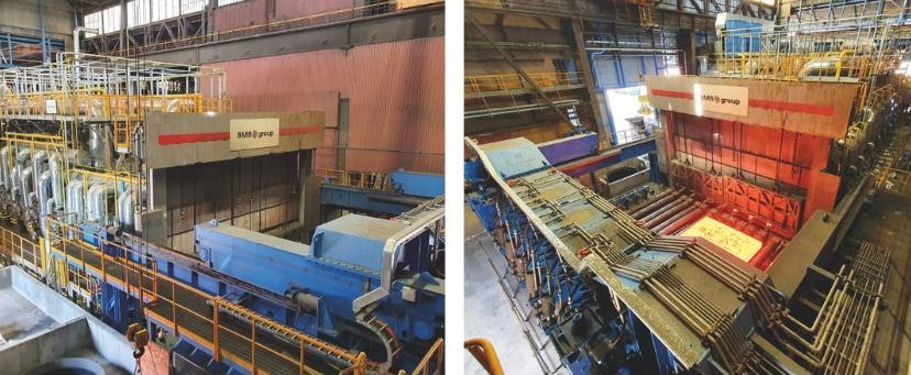
DanSteel Walking Beam Reheating Furnace

In 2022, DanSteel and SMS commissioned a new walking-beam reheating furnace (Figure 3) with a design capacity of up to 100 tonnes/hour, expanding the range of slabs heated to a maximum cross section of H × B 400 × 2800 mm and improving heating quality. The maximum temperature difference between the coldest and the hottest points on the slabs is not more than 30°C. The new furnace has been designed with a focus on environmental and energy efficiency and has reduced CO2 emissions by 17–18% compared to the furnaces already in operation in the plant.

Figure 3. DanSteel walking beam reheating furnace no. 3, (left) general view of the furnace and (right) slab discharging area

The walking beam reheating furnace is for heating cast carbon, low-carbon, and low-alloy steel slabs weighing up to 63 tonnes. The main production characteristics of the furnace as part of DanSteel 4200 rolling complex are shown in Table 1.

Slabs are moved through the furnace by moving the walking beam in four steps: lifting, moving forward, lowering below the level of the fixed beams, and moving the walking beams backwards. The speed of the slab moving in the furnace is controlled by changing the movement intervals between the movement cycles of the beams and depends on the variety of heated slabs. Slab discharging from the furnace is carried out shock-free, using a special machine that moves the slabs from the furnace beams to the mill roller conveyor. The furnace is equipped with a modern automated process control system and a system of instrumentation and sensors that allows the heating of steel without the direct involvement of technical personnel and provides for the measurement, regulation, control, and recording of all operating parameters.

The furnace type is reheating, walking beam, regenerative, multi-zone, double-row, double-sided heating, frontal charging, and discharging furnace. The furnace is designed for natural gas operation with the possibility of a quick conversion, within three weeks, of up to 40% of the capacity for hydrogen operation. The conversion is carried out by means of a minor modernization of the burner’s inner circuit, the installation of hydrogen storage auxiliary equipment and the regulation of the hydrogen supply to the modified nozzles. It is planned that the replacement of natural gas by hydrogen will also reduce the consumption of natural gas by ~40% and hence reduce the negative impact of the process on the environment. Feeding control as well as optimum pressure is controlled by a special automated control system. Table 2 shows the main technical characteristics of the furnace.

The air is heated in a metal recuperator, located on the furnace roof. The combustion products pass between the tube and the air passes through the recuperator tubes. The air is blown by a blower into the recuperator and transported to the burners through thermally insulated air ducts. The gas and air from the common pipelines are supplied to each zone via zone headers, on which flow meters and actuators for flow controllers are installed to ensure an ideal furnace atmosphere with an O2 content of about 0.7–1.0 %.

The furnace has 6 heating zones, 3 upper and 3 lower, with 24 SMS-ZeroFlameTM burners (Figure 4a) for ultra-low nitrogen oxide concentrations and high thermal efficiency.14 The burners consist of a metal casing with external cladding for heat protection, several fuel and combustion air lines, a pre-combustion chamber and an air deflector made of refractory material with high alumina content.

Figure 4. SMS-ZeroFlameTM burners used in DanSteel’s walking beam furnace: a – burner structure; b – flame operation; c – flameless (“invisible flame”) operation

The particular design of the installed burners allows them to operate using three modes:

  • Flame mode (Figure 4b), used for ignition and at low temperature, but even then, the NOx level remains low thanks to the triple-stage air supply
  • Flameless mode (“aka invisible flame,” Figure 4c), which ensures high slab heating uniformity over the cross section creating a homogeneous, invisible flame with minimum NOx emissions
  • Mixed “booster” mode, allowing a 15% to 20% increase in nominal heat input, and a rapid increase in zone temperature if the furnace setting is changed due to a change in steel grade or increased capacity
Figure 5. Heating curves of a 250 x 2800 mm slab in the new reheating furnace no. 3

The combustion gases from the gas combustion heat the metal through direct radiant heat transfer, as do the combustion gases heat the burner units, the furnace roof and walls, which in turn heat the slabs in the furnace through indirect radiant heat transfer. The optimum combination of burner arrangements ensures intensive and uniform heating. The mutual movement of combustion gases and metal is counter current. Combustion gases from the recuperation zone are conveyed by a waste gas duct to the heat exchanger (where they heat the air) and then through a waste gas intake to the chimney and exhausted to the atmosphere. The rotating valve is installed in the exhaust duct between the recuperator and the chimney and is used to control the pressure in the heater.

Figure 6. Heating curves of a 400 x 2800 mm slab in the new reheating furnace no. 3

The skids are cooled by chemically treated water, which circulates in a closed circuit. A dry fan cooling tower is used to dissipate the heat from the cooling water. Steel is charged into the furnace by a charging machine that moves the slabs from the charging roller table to the furnace skids.

Technical Features of Slab Heating

The highly even heating of slabs in furnace 3 of DanSteel is ensured by the optimum arrangement of the burners, flameless fuel combustion, triple skids shift, and warm riders on the skids. The evenness of the slab heating corresponds to a maximum temperature difference in the longitudinal section of up to 20°C, and the maximum difference between the coldest and hottest points of the slab must not exceed 30°C.

Earlier in work15, it was shown that when heating a 250 mm slab in the old furnace no. 2, the maximum temperature gradient was for a long time within 250-300°C, and at the exit of the furnace the slab had a sensitive temperature difference in cross section. Figure 5 shows an industrial schedule of heating slabs cross-section 250 x 2800 mm in the new furnace no. 3. Analyzing thermal and technical data of slab heating for heavy plate production using the new furnace, it should be noted that the slab temperature uniformity distribution during the whole heating period is essential. When heating slab cross-sections 250 x 2800 mm in the new furnace, the maximum temperature gradient does not exceed 130°C (Figure 5). The peak values of temperature gradients are situational in nature and appear only for a short period of time and at times of adaptation of the control model of heating for each specific slab in the active zones of the furnace. For slabs with a thickness of 250 mm the most critical time is the time interval between approx. 90 and 120 minutes during which the upper and lower surfaces of the slab are actively heated. During the last 20 minutes in the soaking and equalizing phase, the temperatures at ¼, ½, and ¾ of the slab thickness reach a maximum gradient of no more than 20°C. As can be seen from the graph in Figure 5, heating of 250 x 2800 mm slabs to a given temperature of 1150°C takes no more than 4.5 hours. It is possible to reduce the heating time, however, with a certain decreasing of quality.

Figure 7a-b. Temperature gradients of 120 mm heavy plate, produced using TM+ACC modes: a, b — top surface thermoscanner data

A similar schedule for heating 400 x 2800 mm slabs is shown at Figure 6. For large cross-section slabs with a thickness of 400 mm, the heating time is in the range of 9–10 hours. The heating time can be reduced to 8 hours, but also with a decrease in the quality of heating towards an increase in the temperature gradient across the thickness of the slab. It should be noted that the temperature increases smoothly in the heating curves at ¼, ½, and ¾ of the slab thickness. From the peaks of the upper furnace temperature curve, the discreteness of the adaptation adjustments of the furnace heating control model can be evaluated.

Heavy Plate Temperature Profile

The DanSteel 4200 Rolling Complex is equipped with twelve control pyrometers and three thermo scanners that measure the temperature of 100% of the top surface of the plate at reference points in the heavy plate production process. The data obtained can be used to accurately and in real time evaluate the temperature uniformity of the plate in width and length direction.

Figure 7 c-f. Temperature gradients of 120 mm heavy plate, produced using TM+ACC modes: c, d (top) — temperature profile of top surface from pyrometer; e, f (bottom) — temperature profile of bottom surface of plate from pyrometer

As an example, Figure 7 shows the results of a scan of the surface temperature of 120 mm thick rolled steel heavy plate after deformation stage is completed and before the start of final cooling in an accelerated cooling unit. Two states of temperature gradients occurring during production are considered: uneven heating and uniform heating. Figure 7a shows the temperature field of a plate with expressed temperature irregularity. The main reason for the marked irregularity in the temperature field of the rolled plate is non-optimal modes of heating of the slab. It can be seen that the central part of the plate has the temperature specified by the technology, while the head and tail overheated by 50-60° C relative to the specified temperature at a maximum permissible deviation of not more than 30°C. Figure 7b shows the temperature field of a plate with a high degree of uniformity. Approximately 95% of the surface of such a plate is at the process-specified temperature with a deviation of ±3°C. The maximum temperature gradient does not exceed 10°C.

The temperature profiles of the top (Figure 7c and Figure 7d) and bottom (Figure 7d and Figure 7e) rolled surfaces, obtained from control pyrometers, show that the nature of the temperature non uniformity is repeated on the upper and lower surfaces of the plate. In the first “non-optimal” case the temperature gradient of the top surface reaches about 76°C, and on the bottom surface: -54°C. In the case of uniform heating, the gradient of the top surface of the plate does not exceed 3–6°C and the bottom surface: 5–11°C.

Preventive Maintenance System

The DanSteel new walking beam furnace is also equipped with an innovative maintenance support tool named SMS Prometheus PMS (Preventive Maintenance System). It consists of a software platform collecting and elaborating the data provided by an extended number of sensors strategically placed over several mechanical components of the furnace, with the goal of predicting possible malfunctioning. The monitored equipment includes the key handling devices, like the slab charger, the slab extractor or the walking beam system, as well as the hot air recuperator, the combustion air fans of the main components of the water treatment fan. The software algorithm is able to extrapolate some data from the sensor measurements to assess the key performance trends of the related component and anticipate the necessity of intervention for maintenance or repair before any actual damage happens.

Figure 8. Dashboard handling — monitoring of the walking beam system

In the example of Figure 8, the trends are shown that correlate the walking beam movement and the cylinders pressure to the slab load inside the furnace. Any significant deviation in respect to the foreseen pattern denotes a movement anomaly and will trigger a notification to the control system, that allows the plant maintenance team to act preventively in view of a potential failure.

Conclusion

A new walking-beam reheating furnace with a designed productivity of up to 100 t/h was put into operation at DanSteel rolling complex 4200. This allowed expanding the range of heated large-size slabs with a maximum cross-section of H x B 400 x 2800 mm and weighing up to 63 tonnes. The implemented project has provided increased uniformity of heating along the thickness, width and length of slabs with average maximum values of temperature gradients in the three directions not exceeding 30°С (80°F) and reduced consumption of natural gas to the level of 31–32 m3/t of finished product. More uniform heating of slabs ensured improved temperature field uniformity of rolled heavy plates. The constructive possibility of a partial transition to the use of hydrogen instead of natural gas was taken into account.

References

  1. I. Sarkits, Y. Bokachev, E. Goli-Oglu, “Production of heavy plates on the rolling mill 4200 DanSteel A/S,” Stahl und Eisen. 2014. no. 4, 57–61.
  2. Imao Tamura, Hiroshi Sekine, Tomo Tanaka, Chiaki Ouchi, Thermomechanical Processing of High-strength Low-alloy Steels (Butterworth-Heinemann, 2013), 256.
  3. Antonio Augusto Gorni and José Herbert Dolabela da Silveira, “Accelerated Cooling of Steel Plates: The Time Has Come,” Journal of ASTM International 5, no. 8 (2008): 358–365.
  4. Y. I. Matrosov, “Complex microalloying of low-pearlite steels subjected to controlled rolling,” Met Sci Heat Treat No. 28 (1986): 173–180.
  5. S. V. Subramanian,, G. Zhu, C. Klinkenberg, K. Hulka, “Ultra Fine Grain Size by Dynamic Recrystallization in Strip Rolling of Nb Microalloyed Steel,” In Materials Science Forum. Vols. 475–479 (2005): 141–144.
  6. S.C. Hong, S. H. Lim, “Inhibition of Abnormal Grain Growth during Isothermal Holding after Heavy Deformation in Nb Steel,” ISIJ International 42, no. 12 (2002): 1461–1467.
  7. K. Hulka, A. Kern, U. Schriever, “Application of Niobium in Quenched and Tempered High-Strength Steels,” Materials Science Forum vols. 500–501 (2005): 519-526.
  8. C. M. Sellars, J. A. Whiteman, “Recrystallization and Grain Growth in Hot Rolling,” Metal Science no. 13 (1979): 87–194.
  9. H. Tamehiro, N. Yamada, H. Matsuda, “Effect of the Thermo-Mechanical Control Process on the Properties of High-strength Low Alloy Steel,” Transactions of the Iron and Steel Institute of Japan Vol. 25, Issue 1 (1985): 54–61.
  10. Sh. Liang, F. Fazeli, H. S. Zurob, “Effects of solutes and temperature on high-temperature deformation and subsequent recovery in hot-rolled low alloy steels,” Materials Science and Engineering A., vol. 765 (2019): 138324.
  11. H. Yada, “Prediction of Microstructural Changes and Mechanical Properties in Hot Strip Rolling,” Proceeding of the International Symposium on Accelerated Cooling of Rolled Steel. Winnipeg, Canada. 1988. 105-119.
  12. W. Roberts, A. Sandberg, T. Siweski, T. Werlefors, “Prediction of Microstructure Development during Recrystallization Hot Rolling on Ti-V-steels,” ASM HSLA Steels Technology and Applications Conference. Philadelphia, USA. 1983. 35–52.
  13. R. Wang, C. I. Garcia, M. Hua, K. Cho, H. Zhang, A. J. Deardo, “Microstructure and precipitation behavior of Nb, Ti complex microalloyed steel produced by compact strip processing,” ISIJ international 46, no. 9 (2006): 1345-1353.
  14. “Innovation in combustion process,” SMS group, https://www.sms-group.com/en-gb/insights/all-insights/innovation in-combustion-process (date of review 2023-03-20).
  15. V. A. Tretyakov, Bokachev, A. Yu, A. N. Filatov, E. A. Goli-Oglu, Development of a digital twin of the process of controlled rolling of thick plate from high-strength low-alloy steels. Message 1. Simulation of slab reheating in continuous furnace with a prediction of austenite grain size before rolling. // Problems of ferrous metallurgy and materials science. 2022. no. 2, P. 30-40.

This article content is used with permission by Heat Treat Today’s media partner Furnaces International, which published this article in September 2023.

About the Authors:

Eugene Goli-Oglu has worked at NLMK DanSteel since 2013 and has led Product Development, Technology and Technical Sales Support functions for steel heavy plate production. Eugene received his Master degree in Metal Forming in 2007, a second Master’s degree in Economy in 2009, and a PhD in Metallurgy and Thermal Processing of Metals and Alloys in 2012. He has authored/co-authored 90+ publications in technical journals.

Sergey Mezinov has worked at NLMK DanSteel since 2007 as an engineer of the Project Department and process engineer of the Quality Department. In 1995, Sergey graduated as an heat-power engineer. He has authored/co-authored of 2+ publications in technical journals and authored/co-authored two patents.

Andrei Filatov has worked at NLMK DanSteel since 2019 as a metallurgist in the Product Development and Technical Sales Support department. In 2015, Andrei graduated as an engineer physicist, and in 2019, he completed postgraduate studies in Metallurgy and Thermal Processing of Metals and Alloys. He has authored/co-authored 20+ publications in technical journals.

Pietro della Putta is the vice president of the Reheating and Heat Treatment Plants department at SMS group S.p.A. Jimmy Fabro is the head of the Technical Department – Furnace Division at SMS group S.p.A.

Jimmy Fabro is the head of the Technical Department – Furnace Division at SMS group S.p.A.


Case Study: The Metallurgy Within a Reheating Furnace at DanSteel Read More »

Near Net Shape, Meet HIP

Source: Quintus Technologies

A major concern with cast products is fatigue resistance and getting the right mechanical properties. Of course, thermal processing plays a role, and for years, hot isostatic pressing has been solving this very problem.

Today’s best of the web article details out how the process can remove shrinkage porosity and internal defect, ultimately leading to a more resistant part for some of the most critical applications: nuclear power.

An Excerpt:

“The production of specially designed canisters can lead to predictive final shapes with extremely complex geometries, which are a viable option to forging, casting and additive manufacturing. The processing is referred to as Powder Metallurgy Near-Net-Shape (PM NNS), or Powder Metallurgy HIP (PM HIP).”

Read the entire article from Quintus Technologies by clicking here: Manufacturing of Nuclear components using Powder Metallurgy Near Net Shape production and Hot Isostatic Pressing


Find Heat Treating Products And Services When You Search On Heat Treat Buyers Guide.Com


Near Net Shape, Meet HIP Read More »

Fusion and Our Future

op-ed

Current energy developments turn our thoughts to the possibility of future innovations. For example, is there a way to generate energy, usable energy, from fusion? Is there hope that this energy can be created and made available to the heat treat industry and other sectors? There seem to be many, many questions that have yet to be answered in the production and utilization of fusion energy.

John Clarke, technical director at Helios Electric Corporation, holds out confidence in the future by standing on the foundation of the past. Comparing the current position of science and research on fusion energy to the early days of aviation exploration, he thinks the sky is the limit for what can be accomplished.


John B. Clarke
Technical Director
Helios Electric Corporation
Source: Helios Electric Corporation

Contact us with your Reader Feedback!

On December 5, 2022, scientists at Lawrence Livermore National Laboratory conducted the first controlled fusion experiment in history. This experiment produced more energy from fusion than the laser energy used to drive it. In this test, the nuclei of two lighter elements were combined to form one new, heavier nucleus. During the process, some of the mass of the lighter elements was converted to energy.

How will this incredible breakthrough affect our lives? Will the promise of limitless, clean, and cheap energy be realized, and if so, when?

I don’t think we can know the answers to the above questions with certainty.  It has always been difficult to foresee the final results of any technological leap forward, and even more difficult to provide a timeframe that encompasses the change.

Think about a time before jumbo jets and commuter flights. That was a time when not a single person had been carried by airplane through the skies. History shows that scientists and thinkers were able to come up with ideas and machines that flew through the air while carrying many. Look at a brief overview of how quickly the aircraft improved.

On December 17, 1903, at Kill Devil Hills, near Kitty Hawk, NC, Orville Wright completed the first powered flight of a heavier-than-air aircraft known as the Wright Flyer. The flight lasted just 12 seconds, traveled 120 feet, and reached a top speed of 6.8 miles per hour. 15 years later, we saw the first airmail and scheduled commercial service. 24 years later, Lindberg flew across the Atlantic. 36 years later, we witnessed the introduction of jet engines, and Chuck Yeager broke the speed of sound just 44 years after the first flight in North Carolina.

Example from early advances in aviation: the Wright Flyer
Source: unsplash.com/historyhd

Obviously, Orville and Wilber Wright would have had difficulty foreseeing the aircraft's advancements and would never have predicted a time frame. Why is timing the rate of advancement so difficult?  Airplane development benefited from the convergence of multiple independent and unrelated technology, and there was the will to develop more advanced aircraft for both military and civilian use.

So, back to the first question posed – will the promise of limitless, clean, and cheap energy from fusion be realized? I am going to say yes. Not that I know much about fusion, it is simply that history teaches us not to bet against technology. As for when, well that is a known unknown.

About the Author:

John Clarke, with over 30 years in the heat processing field, is currently the technical director of Helios Corporation. John’s work includes system efficiency analysis, burner design as well as burner management systems. John was a former president of the Industrial Heating Equipment Association and vice president at Maxon Corporation.


Find heat treating products and services when you search on Heat Treat Buyers Guide.com


Fusion and Our Future Read More »

Harnessing the Sun: A Heat Treat Case Study with General Atomics

OC Imagine this: A huge lab facility nestled in the south of France . . . teams of scientists and technicians striving to bring carbon-free energy solutions to the world . . . “replicating the high-energy fusion reaction that powers the sun and stars.” To complete the project, what heat treat solution is needed? Read more in this Technical Tuesday to find out.

This article by Rafal Walczak, product manager at SECO/VACUUM, will be published in Heat Treat Today’s December 2022 Medical & Energy print edition.


Introduction

For this case study, we will discuss how SECO/VACUUM built a highly specialized custom heat treating furnace used in the construction of the central component of a large, multinational science experiment.

The Experiment

ITER (standing for International Thermonuclear Experimental Reactor and meaning “the way” in Latin) is the largest high-energy science experiment ever conducted. At a giant lab facility in southern France 35 countries, hundreds of vendors, and thousands of scientists and technicians are collaborating on a device to demonstrate the feasibility of clean, safe, carbon-free energy production by replicating the high-energy fusion reaction that powers the sun and stars.

Figure 1. ITER Laboratory at the Cadarache research center in southern France
Source: ITER Organization

There are no solid materials that can touch, much less contain, such a high-energy reaction without immediately vaporizing. Instead, this super-hot cloud of plasma must be contained by a special configuration of magnets called a tokamak, which can trap charged particles in a toroidal or donut-shape cloud. This tokamak has 10 times more plasma containment volume than any other tokamak ever built.

The term “tokamak” comes to us from a Russian acronym that stands for “toroidal chamber with magnetic coils” (тороидальная камера с магнитными катушками).

The Magnet

Figure 2. ITER central solenoid and one isolated solenoid module
Source: General Atomics ITER Manufacturing

General Atomics’ Magnet Technologies Center near San Diego, CA was contracted to build the ITER tokamak’s large central magnet, the most powerful superconducting magnet ever built, strong enough to lift an aircraft carrier. Other magnets in the tokamak serve to contain the plasma. The central solenoid is an oscillating magnet responsible for inducing current in the plasma cloud similar to how an induction stove heats a pan, except it is heating the plasma to 15 times the temperature of the surface of the sun. Far too large to be constructed and transported in one piece, the 12-meter-tall, 4-meter-wide coil of wires must be built in six 2-meter-tall modules to be joined once they are all on site at the lab. A seventh module will be built as a spare.

Kenneth Khumthong, technical lead for final testing and fabrication certification for ITER Central Solenoid at GA, described the tests on each module of the magnet, saying, “We run a battery of tests on each and every module subjecting them to voltages as high as 30,000 volts and powering them with as much current as 40,000 amps. This is done to ensure that every module meets all of ITER’s specifications prior to shipping them out to France.”

Embrittlement vs. Field Strength Tradeoff

Other superconducting electromagnets in the ITER tokamak will be made using coils of relatively durable niobium-titanium alloy. Past experiments have demonstrated that magnetic fields greater than 12 Tesla disrupt the superconducting properties of Nb3Ti. The ITER central solenoid, however, must sustain magnetic field strengths above 13 Tesla. For this reason, the central solenoid coils must instead use niobium-tin as its superconducting wire, which more reliably maintains superconducting properties in such high magnetic fields but is also more brittle and too fragile to bend after reaction to Nb3Sn. In order to accommodate for the brittle wire, General Atomics had to first coil the wire and jacket into their final shape before heat treating the metals into their superconducting, albeit brittle, alloy Nb3Sn.

The Wire 

Figure 3. A dissection of the central solenoid conductor strands, central spiral, and structural jacket
Source: ITER Organization
  • Niobium-tin wire strands react to become Nb3
  • Copper strands serve as traditional conductors to safely dissipate stored energy when the superconductivity experiences a disruption. The copper strands do not react with the niobium-tin.
  • A central spiral maintains a hollow channel to circulate liquid helium to chill the Nb3Sn wires to 4°K, below their superconducting temperature of 12°
  • Creating such strong magnetic fields inside a coil of wire will also tear apart the coil of wire itself if that wire is not supported inside a high strength jacket. The ITER central solenoid wire bundle is about 38.5 mm diameter, housed inside a 50 x 50 mm stainless steel jacket.
  • Total maximum current in the superconductor wire is 48,000 amps.
  • Worldwide niobium production increased six-fold for several years just to meet the niobium demands of the ITER project.

The Heat Treating Furnace

Figure 4. Technicians ensure proper placement before lowering heat treat furnace
Source: General Atomics ITER Manufacturing

In order to convert the niobium-tin metal conductors into superconductors, each of these 4 meter by 2 meter 110 ton solenoid sections must be heat treated for five weeks, exceeding 1200°F (650°C) at its peak. The heat treatment serves to alloy the niobium and tin together into Nb3Sn, which becomes a superconductor when chilled with liquid helium to 4°Kelvin. No such heat treating furnaces existed, so General Atomics turned to SECO/VACUUM to build a custom heat treating furnace large enough to fit these solenoids and packed with all the technology needed to meet the strict quality control standards of this monumental experiment.

Five inch wide metal band heaters ring around the walls of the furnace with nearly 900kW of heating power. Covering 50% of the walls, they provide a very uniform heat. This is brought about by the following seven steps.

The Heat Treating Sequence

In addition to alloying the niobium-tin wires, the furnace also serves to remove the stresses in the stainless steel jacket housing the superconducting wire and to bake off any residual contaminants prior to reaching reaction temperature.

1. Complete a quality control test: Vacuum seal the untreated solenoid coil in the room temperature furnace and charge the inside of the conductor jacket with 30 bar high pressure helium to test for leaks after forming and welding.

  • Monitor furnace atmosphere with ultra-high sensitivity mass-spectrometer helium detectors.

2. Purge with argon gas while slowly ramping up heat.

  • This drives off hydrocarbons and oxygen before system reaches reaction temperatures.
  • Monitor furnace atmosphere with gas chromatograph to find impurities from residual oils and lubricants leftover from manufacturing process.
  • Monitor and control argon circulation and exchange with mass flow sensors and circulation blowers that penetrate the furnace lid with ferrofluidic feedthrough seals around the blower motor shafts.

3. Maintain at 1058°F (570°C) for about 10 days. Confirm stabilized temperature and pure atmosphere.

4. Proceed to 1202°F (650°C) for four days. This is the actual reaction phase that achieves the primary objective of converting the niobium-tin into the superconducting alloy Nb3

5. Very slowly and uniformly ramp back down to room temperature to avoid additional stresses in the coil.

6. Complete another quality control test: Evacuate the argon and once again vacuum seal the solenoid coil in the room temperature furnace and recharge with 30 bar high pressure helium to test for leaks after heat treating. Monitor atmosphere for the presence of helium, which would indicate a leak in the coil.

7. Only then is it ready for the post-heat treating stages of wrapping with insulation and encasing in epoxy resin for rigidity.

Options, Upgrades, Special Features

Figure 5. Cutaway illustration showing the furnace construction
Source: SECO/VACUUM

There was no room for error. SECO/VACUUM collaborated with the engineers at General Atomic to create a heat treat furnace that can assure temperature variation within the coil never varies by more than 18°F (10°C) anywhere in the furnace at any time in the five-week cycle and achieves near-perfect repeatability for all seven modules.

They accomplished this with quadruple-redundant control thermocouples and feeding temperature data from 150 points in the coil into the control computers. To shield against impurities, the furnace is first evacuated to a vacuum pressure of 0.001 Torr, and then purged with pure argon to drive out any residual oxygen or hydrocarbons that could contaminate the purity of the superconductor. Monitoring the argon atmosphere for impurities are redundant mass spectrometers. The argon is circulated by seven convection fans to heat the solenoid assembly evenly. Each of these fans must be driven through ferrofluidic feedthrough seals which allow the rotating shafts to operate through the furnace walls without compromising the vacuum seal of the furnace.

Consult, Collaborate, and Partner with SECO/VISORY

General Atomics first began discussing this project with Rafał Walczak, the product manager at SECO/VACUUM, in early 2010. Both teams spent over two years on conceptual discussions, preliminary designs, and process simulations before SECO was even awarded the contract. Once SECO was on board, it took another two years of design, fabrication, and installation before the furnace could be put into operation. SECO/VACUUM built it to handle a lifetime of use without error so they could be sure that it would work flawlessly for the seven cycles that it actually had to run.

The SECO/VISORY Heat Treat Advisory Council is a team of SECO/VACUUM heat treat experts and consultants with diverse thermal experience and process knowledge who are available to help companies solve their specific heat treat equipment challenges.

Rafal Walczak
Product Manager
SECO/VACUUM
Source: Rafal Walczak

About the Author: Rafal Walczak is the product manager at SECO/VACUUM. Rafal joined SECO/WARWICK Group as a service engineer in Vacuum Furnaces Division soon after graduation from Technical University of Zielona Góra in 2002. Since 2008, he has been involved in vacuum furnace sales in Europe and the USA. The combination of his technical background and field service experience help him provide outstanding support to his SECO/VACUUM customers. For more information, contact Rafal at Rafal.Walczak@SecoVacUSA.com.


Find heat treating products and services when you search on Heat Treat Buyers Guide.com


Harnessing the Sun: A Heat Treat Case Study with General Atomics Read More »

Excess Air: Its Role in Combustion and Heat Transfer

Excess air plays multiple roles in heat treating systems. Learn about its importance in combustion and heat transfer, and why being well-informed will help your system run at peak performance.

This original content article, written by John Clarke, technical director at Helios Electric Corporation, appeared in Heat Treat Today’s Aerospace March 2021 print magazine. See this issue and others here.


John B. Clarke
Technical Director
Helios Electric Corporation
Source: Helios Electric Corporation

Is your system running optimally? The following discussion will provide a better, albeit abbreviated, understanding of the role of air in combustion and heat transfer.

Excess air in heating systems plays many roles: it provides adequate oxygen to prevent the formation of CO or soot, can reduce formation of NOx, increases the mass flow in convective furnaces to improve temperature uniformity, and at times, wastes energy. Excess air is neither good nor bad, but it is frequently necessary.

To begin, we must first look at a basic formula. For our discussions, we will replace natural gas, which is a mix of hydrocarbons with methane (CH4). The oxygen (O2) is supplied by air.

The above simplified formula describes perfect or stoichiometric combustion. The inputs are methane and air (where only the O2 is used to oxidize the carbon and hydrogen in the methane), and the products of combustion (POC) consist of heated carbon dioxide (CO2), water vapor (H2O) and of course nitrogen (N2). (The actual reaction is far more complex and there are other elements present in air that we are ignoring for simplicity.) As we can see from the equation, the oxygen we need to burn the methane comes with a significant quantity of nitrogen.

In practice, it is very difficult to even approach this stoichiometric or perfect reaction because it would require perfect mixing, meaning that each molecule of methane is next to an oxygen molecule at just the right time. Without some excess air, we would expect some carbon monoxide and/or soot to be formed. Excess air is generally defined as the percent of total air supplied that is more than what is required for stoichiometric or perfect combustion. For natural gas, a good rule of thumb is to have about 10 cubic feet of air for every one cubic foot of fuel gas for perfect combustion. Higher air/fuel ratios, say 11:1, are another way of describing excess air.

In most heating applications, the creation of carbon monoxide and other unburnt hydrocarbons should be avoided, except in the rare cases where they serve to protect the material being processed. Employees must be protected from CO exposure; and soot can damage not only equipment, but the material being processed.

Source: Heat Treat Today

The amount of excess air that is required to find and combine with the methane is dependent not only on the burner, but also on the application and operating temperature as well. Some burners and systems can run with very little excess air (under 5%) and not form soot or CO. Others may require 15% or more to burn cleanly. Just because a burner performs well at 10% excess air in application A, does not necessarily mean the same level is adequate in application B.

Once the quantity of air exceeds what is needed to fully oxidize or burn the methane, combustion efficiency will fall because the added air contributes no useful O2 to the combustion process, and it must be heated. It is very much like someone putting a rock in your backpack before you set out for a 16-mile trek. Taking this analogy further, higher process temperatures equate to climbing a hill or mountain with that same rock — the higher the climb, or the higher the process temperature, the more energy you waste. Sometimes this added weight or mass can be useful.

The higher the excess air, the greater the mass flow. In other words, the total weight of the products of combustion goes up, and the temperature of the CO2, H2O, N2, and O2 goes down. If we are trying to transfer the heat convectively, this added mass or weight will provide improved heat transfer and temperature uniformity. A simple way to think of temperature uniformity is that the lower the temperature drop between the products of combustion and the material being heated, the better the temperature uniformity. Many heating systems are specifically designed to take advantage of this condition – higher levels of air at lower temperatures. This is especially true when convective heat transfer is the dominant means of moving heat from the POC to the material being heated (when the process temperature is roughly 1000°F or lower).

Source: Heat Treat Today

Some heating systems are specifically designed to operate as close to perfect combustion as is possible as the material is heated then switch to higher levels of excess air to increase the temperature uniformity as the setpoint temperature is approached. In other words, it provides efficient combustion when temperature uniformity is less of an issue and a very uniform environment as the material being processed nears its final setpoint temperature.

Of course, a system can be supplied with too much air, which can waste energy, but also prevent the system from ever reaching its setpoint temperature. The energy is insufficient to heat all the air, the material being processed, and compensate for furnace or oven loses. In these instances, it is obvious that we must reduce the air supplied to the system.

In indirect heating systems – where the products of combustion do not come in contact with the material being processed, like radiant tubes, for example — air in excess of what is required for clean combustion provides limited benefit and should generally be avoided. In these systems, it is best to play a game of limbo, “How Low Can You Go,” so to speak. Test each burner to see how much excess air is required to burn clean and add a little bit for safety. Remember, if you source your combustion air from outside in an area with significant seasonal variations, the blower efficiency will change, and seasonal combustion tuning is required.

Lastly, some burners require a minimum level of excess air to operate properly. This additional air prevents critical parts of the burner from overheating – or the air may limit the formation of oxides of nitrogen (NOx). In this application, altering the burner air/fuel ratio could generate excessive pollutants or even destroy the burner.

Efficiency is important, but the process is king. There is no magical air-to-fuel ratio and no single optimum level of excess air in the products of combustion. Each application is unique and must be thoughtfully analyzed before we can confidently say we have optimized our level of excess air. But careful attention paid to the effect that excess air has on your fuel-fired systems will pay dividends in improved safety and efficiency.

About the Author:

John Clarke, technical director at Helios Electric Corporation, a combustion consultancy, will be sharing his expertise as he navigates us through all things energy as it relates to heat treating equipment.

Excess Air: Its Role in Combustion and Heat Transfer Read More »

Natural Gas vs. Hydrogen Combustion: Reality or Hot Air? – Expert Analysis

OCFossil fuels. Are they detrimental to the environment? Are they past their prime? Is hydrogen what we should be talking about? Are there other technologies that should be capturing our attention?

Heat Treat Today and our good friends at heatprocessing, Europe’s leading heat treat magazine, sought outstanding U.S. and European experts in the energy field to answer and provide analysis about the state of natural gas and hydrogen combustion. This original content piece, edited by Karen Gantzer, managing editor at Heat Treat Today, appeared in the Heat Treat Today 2020 Medical & Energy December print edition. We hope you enjoy this Technical Tuesday.


John B. Clarke
Technical Director
Helios Electric

The following article highlights the insight of seven gentlemen in the heat treating industry, from both the U.S. and Europe, who work within the energy sector. We asked them for their responses to three questions regarding natural gas and hydrogen combustion. Our European colleagues also commented on whether hydrogen will be an important

factor in the heat treat industry in 10 years. There is a diversity of opinions among the experts, and it’s important to note how regional economics and resources may have impacted responses.

We hope you enjoy the analysis from our experts.

Where do you see the natural gas industry today? Where do you believe it will be in 10 years?

John B. Clarke, technical director at Helios Electric Corporation, a combustion consultancy in Fort Wayne, Indiana, shares how different his answer would have been if asked years ago about the state of natural gas: “Had you asked me 25 years ago, I would have described a market with a declining supply of natural gas resulting in rising costs. A market dominated by a drive to increase efficiency to control energy costs. That was then, but now we have an abundant (yet finite) supply of natural gas resulting in very low costs – and in the medium term, a market dominated by a drive to reduce emissions. Increased efficiency – both in the medium term and today – will reduce energy costs while at the same time reduce CO2 emissions.”

Clarke continues, “Given the prevalence of hydraulic fracturing, we can expect an expanding availability of natural gas, if the market price provides a sufficient return for the producers. The greatest disruption in the natural gas market will likely be on the consumption side as electrical power producers continue their shift away from coal to natural gas. While renewables will play a larger part, they cannot meet the requirement to provide continuous base load power to consumers.”

Dave Wolff
Region Sales Manager
Nel Hydrogen

Dave Wolff, region sales manager at Nel Hydrogen, a manufacturer of onsite hydrogen generation, agrees with Clarke on the budget friendly price of natural gas, and he also cautions that it’s a finite resource: “It is an amazing time to be a natural gas user. Natural gas has never been cheaper than it is today ($2.00/MMBTU range). But the super low pricing won’t last forever. It is critical to understand that natural gas reserves are a finite resource, and that at today’s pricing, most shale operations are losing money. The Energy Information Association (EIA) expects that natural gas pricing will go up 50% in 2021 versus 2020.”

Regarding the future, Wolff recommends, “. . . wind and solar energy are truly infinite energy sources. Unlike the volatile and unpredictable natural gas pricing chart, renewable electricity prices are on a steady downward trend... So, I would strongly advise people to test their investment decisions as to the varying picture for natural gas versus electric price predictions. Especially if buying furnaces, this is critical, since the lifetime cost of a furnace is overwhelmingly a function of energy.”

Keenan Cokain, global sales and applications coordinator and Michael Cochran, an applications engineer, both from Pittsburgh’s Bloom Engineering, an industrial combustion and controls company, add another consideration: “Natural gas is a vital primary energy source globally and will likely remain so over the next 10 years. Although energy demands will likely show an overall decline in 2020, over the next 10 years, global natural gas consumption will likely rise as it continues to grow in comparison to other fossil fuels (such as oil and coal) as a percentage of the global primary energy consumed.

"It is important to note that when combusted natural gas (methane) produces about 117 lbs. of carbon dioxide (CO2) per 1 million Btu released, this is lower than oil and coal which produces 164 lbs. and 208 lbs. of CO2 per 1 million Btu respectively. Given the fact that natural gas produces lower CO2 emissions compared to other common fossil fuels, some see it as a bridge fuel that could be used in greater amounts until other fuel sources with lower carbon dioxide footprints are developed."

Do our European colleagues share a similar view?

Dipl.-Ing. Gerd Waning
Market Development
Metallurgy Heat Treatment
Linde GmbH

Dipl.-Ing. Gerd Waning, market development in Metallurgy Heat Treatment at Linde GmbH, a global industrial gases and engineering company, states, “Due to the excellently developed natural gas infrastructure in many European countries, natural gas is today probably the best established energy source in industry and households with a high level of acceptance in terms of environmental friendliness and safety.”

In regard to decarbonization, the removal of hydrocarbons from combustion, Waning shares, “In connection with the strongly accelerated decarbonization of industrial and energy production in Europe, it can be assumed that the share of natural gas in the overall energy business will initially increase through 2030. The scheduled shutdown of coal and nuclear power plants (in Germany) will not be able to be compensated by renewable energy sources during this period, so the deficits in the in-house production of electricity will have to be partially compensated by natural gas.”

Dr.-Ing. Michael Severin
Business Field Manager Process Heat
Karl Dungs GmbH & Co. KG

Dr.-Ing. Michael Severin, business field manager, Process Heat, at Karl Dungs GmbH & Co. KG, a supplier for combustion controls components and system solutions for heating burners, boilers, process heat, and gas engines, introduces climate-neutrality and digitalization to the conversation. “The natural gas industry, with its conservative requirements, is challenged by modern demands for climate-neutrality and digitalization. I believe in 10 years we will have proven that combustion and climate-neutrality are not contradictory, and that safety and security can be boosted by intelligent systems. However, in 10 years these examples will still be pilot projects, with a growing infrastructure and the broad transition happening gradually.”

Lars Böhmer
Managing Director
Research Association for Industrial Furnace Construction (FOGI) within VDMA Metallurgy

.

.

Lars Böhmer, managing director at the Research Association for Industrial Furnace Construction (FOGI) within VDMA Metallurgy, a joint platform of metallurgical machinery producers in Europe, believes the changes that are coming are necessary and will not be a surprise to the natural gas industry. “So, all stakeholders, suppliers as well as users, are in dialogue regarding possible solutions,” explains Böhmer.

Regarding the future, Böhmer states, “The market in 10 years’ time will certainly be a different one than today, and you don’t have to be a prophet to say that alternative fuels will play a greater role than they are currently. Whether these alternative fuels will then be used 100% or as a blend may well depend on many regional, but also technical, parameters.”

What do you perceive to be the eventual move from fossil fuels to hydrogen-based fuels? Why the move away from fossil fuels?

There is a consensus among our experts that reducing carbon dioxide emissions is a universal desire and that the burden to accomplish this goal lies within countries around the world. What is fascinating are the various options they provide to replace the carbon-based fuels.

Cokain and Cochran, from Bloom Engineering, share their thoughts on generating hydrogen on an industrial scale and viable next steps. They say, “The most common way to generate hydrogen today on an industrial scale is through a process called steam-methane reforming. During this process natural gas (methane) and steam are combined under pressure with catalysts in a twostep process to produce carbon dioxide (CO2) and hydrogen (H2). Once the carbon dioxide is removed, one is left with pure hydrogen that can be used as a carbon-free fuel source. The downside to steam-methane reforming is that by the time the steam is produced and the carbon stripped from the natural gas, the resulting carbon dioxide emissions can be on the order of 40% more per unit of fuel energy produced than would have resulted from the direct combustion of natural gas. This means that without being coupled with carbon capture and store (CCS) – capturing the CO2 before it leaves the plant – a move to hydrogen based fuels generated using today’s most common methods of hydrogen production would result in an increase of carbon dioxide emissions into the atmosphere.”

The Bloom team continues, “Other methods of producing hydrogen that would not result in increased generation of carbon dioxide are currently being developed. One such method would be electrolysis or the use of electricity to decompose water into hydrogen and oxygen. If the electric for such a process were generated using renewable or ‘carbon neutral’ sources, then the carbon penalty associated with hydrogen production could be eliminated.”

Nel Hydrogen’s Wolff contends, “It seems straightforward that forever energy sources are going to be less expensive in the long run than finite ones. No matter what your environmental politics, the facts are that finite resources go up in price as supply shrinks relative to demand.”

“Hydrogen for the heat treat industry is unlikely to be used as a fuel – it is used as an atmosphere component, with diluents such as nitrogen or argon, and with carbon-contributors such as methanol or even methane itself,” Wolff continues. “Long-term, we at Nel expect that hydrogen produced on-site will be the predominant hydrogen-containing atmosphere approach.”

Clarke of Helios Electrical Corporation is a believer in battery technology, “The movement from coal to natural gas is, in essence, a move from full carbon to a carbon/hydrogen fuel. As for pure hydrogen fuel cells, there may be new technology that drives the costs down, but my bet is that battery technology advancement will push fuel cells from most applications.”

While the economic impact on the infrastructure to build thousands of recharging stations will surely be a consideration for the future of electric cars, Clarke says, “I believe we will see an accelerated movement to electric vehicles. Battery technology has reached a point where the range of these vehicles are acceptable for an increasing number of consumers.” Clarke continues, “This will move consumption from gasoline and other petroleum- based fuels but may increase demand for natural gas for power generation.”

“In the end,” Clarke explains, “it always comes down to economics – cost of new equipment, cost of operating, and cost of regulation. I believe current users of fossil fuel heating equipment in the industry can expect the cost of equipment and regulations to increase. More efficient technology with heat recovery will cost more to purchase and install, and we can expect regulatory compliance costs to increase. As for cost of operating the equipment, I am optimistic that decreased energy consumption might offset increased energy costs.”

Karl Dungs GmbH & Co.’s Severin shares two options for transitioning to include hydrogen in a combustion system: “Hydrogen as a chemical energy carrier makes green electric power storable and utilizable for industries where large amounts of heat and high temperatures are required. Infrastructure and gas systems can be used with hydrogen with minor adaptations to the combustion system. For the transition, there are two possible ways. Either hydrogen is blended into natural gas networks and the ratio will be ramped up over the years. Or, parallel hydrogen networks will be created, which supply particular plants with 100% hydrogen now and will then grow and spread into the rest of the industry over the years. The determination between these scenarios is hard to foresee at the moment, but I personally see a trend towards the latter.”

Böhmer, of VDMA, knows there are field tests with fuel/gas mixtures containing 20% hydrogen, however he thinks we’ll see “an intermediate step of about 60% hydrogen, since there is little experience beyond this value. The question that plays a big role regarding this topic is, ‘How much hydrogen, which is produced by means of renewable energy, will be available at all?’”

Waning, from Linde GmbH, addresses the longevity of furnace systems and new systems versus conversions: “Due to the long service life of heat treatment systems, there will be only a few systems built exclusively for hydrogen as a heating medium. The technological feasibility of converting from natural gasfired systems to hydrogen-fired systems or a mixture of natural gas and hydrogen (50/50) is only just beginning to be researched on an industrial scale, whereas the conversion of the infrastructure to high hydrogen concentrations is considered manageable. However, this changeover should not be critical, particularly in the case of heat treatment systems that are fired with closed radiant heating tubes due to their protective atmosphere operation."

Should captive heat treaters be talking about hydrogen or are there other technologies they should be focusing on?

Linde GmbH’s Waning states that there are no significant differences between contract heat treaters and in-house heat treaters because of the comparable systems used by both. However, he does encourage us to focus on the period after 2023. He says, “Here it becomes clear how strongly development depends on current local political action. France, for example, continues to consistently focus on expanding the use of electricity. Here the heat treatment company is well advised to operate electrically heated systems if they want to minimize their CO2 footprint. Paired with nitrogen-methanol or hydrogen as a protective gas from green sources, a heat treatment process with the lowest CO2 emissions can be created.”

“In Germany,” Waning continues, “the picture is completely different. The move away from coal and nuclear power towards renewable energies led to the recently adopted German hydrogen strategy. There is no getting around the increasing use of hydrogen as a combustion medium, as the regulations for a massive expansion of the electrical networks in Germany lead to extremely long implementation times. While the same must be said here for the protective atmosphere side as for France and all other countries, the heat treatment company in Germany should consider being able to react flexibly to the actual conditions with hybrid heating (electric + gas).”

Severin, from Karl Dungs GmbH & Co., talks about biogas: “Biogas can have the same CO2 -neutral balance as hydrogen and has a better availability in many regions nowadays. However, biogas will always be a very limited resource and will not be able to serve a whole industry segment. Other climate-neutral fuels, like synthetic methane or higher hydrocarbons, always involve a loss in overall efficiency. In the long run, I only see hydrogen as a feasible and comprehensive solution for green combustion technology.”

VDMA’s Böhmer cautions against thinking that hydrogen is the silver bullet to solve the climate challenges: “In my opinion, considering hydrogen as the one and only solution to climate problems would be the wrong way to go. Hydrogen is one of several possible solutions, although it has already turned out to play a very important role against the background of the already mentioned storage possibilities of regeneratively produced energy. But it also has to be taken into account that the hydrogen, be it as combustion gas or as basis for further conversions, has to be available everywhere it is needed and in the required quantities.”

Böhmer also reminds us there are possible solutions in the world of synthetically produced fuels that are not exclusively hydrogen-based. In fact, “in the aviation industry, the use of sustainable kerosene from ‘power-to-liquid’ plants is not only being discussed but is already being tested. So, the fuel of the future does not necessarily have to be only gaseous, and actually there are many different approaches and efforts to reach the targets.”

To the heat treater, Böhmer emphasizes that electric heating, i.e., inductive hardening, “must not be missing. It can be assumed that the share of electrical heat treatment will increase, as the use of pure or blended hydrogen as fuel gas may be critical, depending on the process and material.”

Helios Electrical Corporation’s Clarke doesn’t believe hydrogen as a heating technology is a viable option. He says, “Obviously, hydrogen as an atmosphere will continue to be used. Burning hydrogen to generate heat is more problematic – heat transfer from the flame to the work being heated (or inside of a radiant tube) is a function of radiation and convection. The hydrogen flame will lack much of the luminosity we have come to expect when burning CH4. The change in luminosity will alter the heat transfer mechanism, providing greater heat flux over a smaller area. Hydrogen also has a very high flame propagation rate.” He mentions the cost of producing and transporting hydrogen must enter into the equation.

Clarke continues, “As an industry, we still have a great deal of energy that can be extracted from the exhaust products of natural gas-fired equipment.” Although he points out that “current economics make the deployment of more advanced technology to capture and reuse this heat unattractive in many cases,” he expects “the cost of natural gas and/or the demand of regulations may very well change this equation in the 10-year time frame.” (In North America, unfortunately, mandated regulatory compliance may be the only viable adaptation of this technology.)

One last opportunity that Clarke mentions is “the efficiency gains that result from improving equipment maintenance, adjusting fuel/air ratios to reduce excess air, cleaning heat transfer surfaces, and maintaining combustion chambers at the optimum pressure to decrease tramp air. Deploying new technology is like a football team hiring a star quarterback. He is not too valuable if the team ignores basic blocking and tackling.”

Bloom Engineering’s Cokain and Cochran think the response from captive heaters may very well be dictated by the area in which they do business, as discussed earlier. “In some places, the goal of reducing carbon dioxide emissions at the point of use could outweigh the fact that hydrogen generation, specifically using steam-methane reforming (SMR) which is most common today, often carries a carbon penalty and is more costly compared to the direct combustion of natural gas. Unless hydrogen production, specifically through SMR coupled with carbon capture and store (CCS), can be made more cost effective, heat treaters in these carbon-regulated areas may want to consider electrification if their process permits.”

They continue, “Unlike some other pollutants that have a largely localized effect, carbon dioxide (CO2) is expected to make the same contribution to global climate change regardless of where it is released. As a result, decarbonization regulations would need to be applied globally to be effective. Otherwise, heat processing industries will likely shift away from regulated regions due to the cost advantages of operating in unregulated areas and continue to add CO2 to the atmosphere.”

And lastly, the Bloom team advises this approach, “Today, the best way for captive heat treaters to minimize carbon dioxide emissions would be to maximize process efficiency and minimize energy use. In other words, burn less fuel and use less electric. For any process that relies on the combustion of fossil fuels, an increase in efficiency that results in a net reduction of fuel burned will proportionally reduce carbon dioxide emissions. One possible way to increase efficiency in a combustion process would be to recover heat from that process’s waste gases through the use of a recuperator or regenerative burner technology. These types of technologies can greatly increase efficiency, but they must be carefully applied since they are not compatible with all combustion processes.”

How important will hydrogen be for the heat treatment industry in 10 years?

Our European experts share their thoughts on the role of hydrogen in the heat treat industry in the next decade.

Waning of Linde GmbH suggests, “Many heat treatment processes that are currently operated with carbon-containing protective atmospheres could alternatively also be operated with very high hydrogen contents. From the current state of technological knowledge, it is mainly atmospheric carburization systems that require a significant proportion of carbon monoxide in the atmosphere in order to be able to operate economically. (Such processes can, however, also be operated with a low CO2 footprint if they are operated with nitrogenmethanol from renewable sources.)”

“Assuming a high availability of inexpensive hydrogen, many operators would opt for the protective gas with the higher hydrogen content, especially since this would result in other significant advantages in terms of furnace life and cleanliness of the systems and quenching medium,” states Waning. “On balance, it can therefore be assumed that in the future there will be a higher hydrogen demand in the heat treatment industry for the protective gas sector alone.”

Karl Dungs GmbH & Co.’s Severin responds, “This depends highly on the regional availability, national regulations, and subsidies. I see local ‘valleys’ of hydrogen grids, with the heat treatment industry being one of the drivers to demand a carbon-neutral energy source, where electrification is not possible. Cost is the main obstacle for this option, so cost reduction in international supply chains, infrastructure, and applications with large consumption is key. In 10 years, this won’t be achieved fully, and hydrogen solutions will still be more expensive than natural gas combustion.”

“Hydrogen will certainly play a greater role for the heat treatment industry than it does today,” states Böhmer, of VDMA. “Regardless of whether pure hydrogen, a natural gashydrogen blend or synthetic natural gas produced by methanization is used in the combustion processes; the fact is that hydrogen will play an important and decisive role as fuel-gas for combustion processes. In this context, the possibility of storing energy by means of hydrogen should not be forgotten in energy-intensive fields such as the heat treatment industry.”

Böhmer concludes, “Nevertheless, it also has to be taken into consideration that there may be a possible influence of hydrogen not only on the burner and the fuel supply regarding choice of materials and safety-procedures, but especially on the material to be treated. Therefore, a possible conversion of hydrogen into synthetic gases must be considered in some cases. It goes without saying that the efficiency and costs play a decisive role in this context.”


For more information, contact the experts:

  1. John B. Clarke, Technical Director, Helios Electric Corporation: jclarke@helios-corp.com
  2. Keenan Cokain Global Sales and Applications Coordinator, Bloom Engineering: kcokain@bloomeng.com
  3. Michael Cochran, Applications Engineer, Bloom Engineering: mcochran@bloomeng.com
  4. Dave Wolff, Region Sales Manager, Nel Hydrogen: dwolff@nelhydrogen.com
  5. Dipl.-Ing. Gerd Waning, Market Development Metallurgy Heat Treatment, Linde GmbH: gerd.waning@linde.com
  6. Dr.-Ing. Michael Severin, Business Field Manager Process Heat, Karl Dungs GmbH & Co. KG: m.severin@dungs.com
  7. Lars Böhmer, Managing Director, Research Association for Industrial Furnace, Construction (FOGI) within VDMA Metallurgy: lars.boehmer@vdma.org

Natural Gas vs. Hydrogen Combustion: Reality or Hot Air? – Expert Analysis Read More »

Heat Treat Radio #41: Rethinking Heat Treating (Part 3 of 4) — The Fracking Pump Valve Seat

Heat Treat Radio host Doug Glenn talks with Joe Powell of Integrated Heat Treating Solutions in this third of a four episode series about bringing heat treating into the 21st century. This episode covers the fascinating heat treatment of a fracking pump valve seat. 

Below, you can either listen to the podcast by clicking on the audio play button, or you can read an edited version of the transcript.


The following transcript has been edited for your reading enjoyment.

Doug Glenn (DG): We're continuing our conversation with Joe Powell of Integrated Heat Treating Solutions. on rethinking heat treating.  I strongly recommend that you listen to parts 1 and 2 of this series as well as today's episode.  All three are fascinating.  To hear the first two parts, click here.

Today, we’ll be talking about what I think, if you've listened to the first two episodes of this four part series, is a very fascinating, I think, somewhat revolutionary advancement in heat treat.

Today, basically what we want to talk about is a really interesting example of the general concept of what we talked about in session one. I want to review that first session very briefly and ask you a couple of other quick questions before we jump into the example of a fracking pump valve seat, which is where we're headed today.  But first, maybe from a 30,000-foot view, Joe, tell us what we're talking about here.  If you were to put this in a minute, how would you describe what it is you've been doing over at Integrated Heat Treating Solutions?

Joe Powell (JP):  Integrated Heat Treating Solutions (IHTS) is a consultancy that takes 75 years of practical commercial heat treating and applies it to help part-makers make better parts by using heat treating knowledge. We also work with the material-makers who want to get more added value out of a given hardenability material.  What IHTS is essentially doing is taking off from the idea that quenching causes the most problems in heating: it causes distortion, part cracking and size change that is unpredictable. That distortion engineering has been part of the ASM and other societies that have had task forces, committees, and various conferences that are dedicated to the control of distortion.

Potential factors influencing distortion
(Source: American Gear Manufacturers Association, sourced by Joe Powell)

The reality is that the control of distortion has been approached by many, many people, including Dr. George Tautin, who was one of the inventors of the reverse solubility polymers when he worked for Dow Chemical and Union Carbide, and Dr. Kovosko in the former Soviet Union, who was my partner in IQ Technologies starting back in 1999.  What we've discovered working with all of these very smart people is that the quench cooling rate and its relationship to causing part distortion or part cracking is a bell shape curve.  In other words, if you quench very slowly in air or gas or hot oil or martemper salts, hot salts for austempering, you will not crack the part.  But, if you quench faster in brine, water, or even water polymer mixtures that don't have enough polymer in them to act like an oil quench, the cooling rate will become relatively fast. That relatively fast cooling rate will give you a much higher probability of part cracking, until on some parts you'll literally crack every part you put in the quench if it's quenched in water.

If you can create a shell on the outside of the part and quench it 752°-1112° F (400°- 600° C) per second, that shell will literally hold that hot part while the hot core thermally shrinks underneath and pulls that shell under compression.  As that thermally cooling shell and hardened shell of martensite goes through volume change and actually increases in volume, the grains are actually pushed up against each other under compressive surface stresses, and that compressive surface stress holds the part like a die.  So, regardless of its geometry or mass, that part is going to come out of the quench having cooled by uniform conduction down to its core through that shell in a very predictable shape.

DG:  That's exactly what I wanted to get to: what we're talking about here is a quenching issue. It's quenching parts fast enough so that, in a sense, what you're doing is creating a hard outer, immovable shell, if you will, pretty much instantaneously, which holds that part in place while the core cools down to the temperature that is needed.

The quenching media, in one sense, don't really matter.  It can be done.  The issue is getting that shell formed quickly, uniformly and then holding it at a certain temperature until the core cools.

You and I have spoken in the past, Joe, about a kind of interesting quote which I'd like you to comment on before we get to the fracking pump valve seat example of what we're talking about. Here’s the quote I'd like you to address, “Everyone knows how to heat treat.  All you need is a torch and a bucket of water.”

"Every day I learn that in the 23 years that I've been working on heat treat quenching and focusing on that and controlling of distortion, there is always something new, and there is always something new in the field of, what I call, metallophysics."

JP:  That's correct.  Every machinist you'll ever meet, and even a machining handbook, will tell you how to heat treat a part, and do it quick and dirty.  The problem is everybody thinks that it’s because they've heat treated a part in the past, that they know a lot about heat treating, and that is just not the case.  There is so much to know, that all I can tell you is that every day I learn something new. Every day I learn that in the 23 years that I've been working on heat treat quenching and focusing on that and controlling of distortion, there is always something new, and there is always something new in the field of, what I call, metallophysics.

DG:  Right.  It brings me back to a couple of thoughts along that line.  One, it's the whole idea that “a little knowledge is a dangerous thing” – we think we know and yet, we don't.  You've told me a story in the past and I think it's worth our listeners hearing it, and that is just an abbreviated version of the Jack Wallace story.  Again, Jack Wallace, the head heat treat metallurgical guru at Case Western Reserve University, comes into your shop and you tell him, “I can quench these things so super-fast,” and he looks at you and says, “You are a crazy man.  It's not possible.”

JP:  Actually, it was worse than that.  Dr. Michael Aerinoff came from Russia and was telling Jack about this technology that Dr. Kovosko discovered back in the former Soviet Union.  So, it had two strikes against it.  Not only was it new information and contrary to the idea that the faster you quench, the more likely you are to blow up the part, but it was also contrary to the information, “Hey, we're in the United States.  We know all about heat treating and metallurgy!”  At the end of the day, this metallophysics twist that Dr. Kovosko put on the dynamics of the heating and cooling process is really the key to understanding and viewing metallurgy from another dimension – the dimension of residual and current compressive stresses that are affecting the part.  That's what Dr. Kovosko told us about, and finally, that's what unlocked the ability of the parts that Professor Wallace witnessed being quenched and not cracking.

DG:  I would have loved to have been there and seen the eyebrows of Dr. Wallace.

JP:  The other two metallurgists who were in the room besides me – two owners of heat treating companies, Wayne Samuelson of Shore Metal Treating at that time and John Vanas at Euclid Heat Treating – both of them basically wrote Michael off as a crackpot because they had heard what professor Wallace had said.  I was the only one dumb enough to think, “Well, come on down.  If you want to demonstrate some parts, they're either going to blow up or they're not.  If they don't blow up, it'll be interesting, and if they do blow up, it will be funny, so let's try it!”

DG I wanted our listeners to hear some of the other people who are now, as I say in quotes “true believers.”  You've got Jack Wallace who now believes what you say is actually true.  You've also got, I believe, George Tautin, who is kind of the “king of quench.”

JP:  Absolutely.  He's actually written a book with us.  It's an ASTM book; it's publication #64, I believe, and that book tells you exactly how to build the first and second generations of IQ (intensive quenching) equipment.  George also said in 2014, after he retired from making polymer quenches, that you don't really need oils or polymer quenches.  You can do quenching very nicely with a properly designed quenching system and water, or water and a little bit of salt.  That was a pretty strong statement from a guy who literally spent his career making those quenches better.

DG:  You had mentioned one other individual, Robert O'Rourke.

JP:  Yes, he is a metallurgist with over 30 years of experience with ductile iron.  Bob worked with one of the industry giants, Chip Keough,* who founded Applied Process and also austempered ductile iron. Chip's company not only worked with the ductile iron society for many years, but also with Bob O'Rourke, who was one of the principals at the Ductile Iron Society; in fact, he was president back in 2015. At the end of the day, he basically said that we could take this kind of crappy material, ductile iron, and austemper it.  Chip made a very good business out of austempering ductile iron at Applied Process and converted many, many parts from either as-cast ductile or even steel parts to austempered ductile iron parts.

That, to me, showed that it's possible to take a heat treating process and apply it to a material and literally create a new material out of as-cast ductile irons.  Chip even said, “I know what you guys are doing.  When we quench in salt, it's very uniform.  There is no film boiling.  There is no nonuniformity in the cooling.  All you're doing is just kicking it up a notch with higher intensity and knocking off the film boiling with the intensive agitation.”  And I said, “You're absolutely right, Chip.”  What we did not know at that time was that it could be applied to ductile iron.

DG:  Let's jump into this fracking pump valve seat.  A couple basic questions.  First off, we're talking about a pump that is used in the fracking industry to extract out, I assume, the fracking fluids, and things of that sort.

JP:  It's actually to inject the high-pressure water sand.  They call the sand a proppant.  After the pump has fractured the shale layers, then they inject water and sand to hold up and prop up those cracks in the geology and allow the gas to flow out more quickly.

DG:  Good.  So, the point is, it is very rugged and the pump takes a beating.  What was the problem that the company was having?  How did it come to your attention?

JP:  The frackers were having to rebuild the pumps every 40-60 hours and replace these valve seats.  They had high pressure water and sand flowing through the valves. The valve would open and close under pressure at about four times a second, and that constant abrasion of the valve opening and closing and banging into the seat was causing the seat to wear out. Once the seat is worn, then the pump can't maintain its pressure, and they're not getting anywhere in terms of putting that fluid down in that well, and therefore, making it produce more oil and gas products.

DG:  Essentially, you've got fracking companies who are having to replace valve seats and rebuild the valves every 40-60 hours.  What was the material that was being used for the valve seat?

JP:  For years, these types of seats were made of 8620 carburized steel.  They usually start with a forged ring, and then they machine that ring into a valve seat with a taper and a strike face where the valve closes onto the valve seat.  That part is generally carburized around 90,000th of an inch effective case step and tempered and then put into the pumps.  Again, that case hardened surface is 60–65 Rockwell and wears very, very well and resists the abrasion of the sand and water.  Because it's 8620, it has a ductile core underneath the strike face that absorbs the impact of the valve opening and closing on top of it every four seconds under pressure.

You have to have a combination of hard, yet ductile.  And you have to have a tough part that resists wear and abrasion.

DG:  These guys were using it and still having to replace it every 40-60 hours, so what was your thinking on it and how did you guys help?

JP:  A whole bunch of people had tried to put tungsten carbide inserts into the strike face to make the strike face even harder than case hardened material.  Then a company came out with a solid sintered tungsten carbide valve seat that costs upward of $500–800 each. You’ve got to remember that there are ten of them in the pump, and they were built as a lifetime valve seat because they actually outlasted the pump block and some of the other parts of the pump.  But that was not a great solution because, at that point, you have a seat that's lasting longer than the pump block. You still had to take apart the pump anyway for other things that were worn; it's too good and it's too expensive.  If you've got $8,000 worth of seats, you're not going to throw the pump block out because it's worn out, you're going to try to remove those seats.

Large Rolls on Their Way into IQ Tank
(Source: Joe Powell)

Again, what they were looking for was a longer life valve seat, not necessarily a lifetime valve seat, but something that would last for all of the stages used by that pump at a certain well.  They would move it at the time that the well completely fracked and started to produce and take it back and rebuild it at their shop.  They were shooting for 200 hours.

DG:  Right.  Again, the normal was 40-60 hours with the 8620 material.

JP: Right.  Having had the experience with the elongator roll and the ability to make something that was literally so hard they couldn't knurl it, we had to temper those elongator rolls back quite a bit in order for them to knurl them and then use them at the mill.  I thought, if we don't temper the valve seat back and just leave it that hard, it should be carbide-like hard, because if a carbide tool can't knurl it, it's pretty doggone hard.  We fired up our existing piece of equipment that we had at Akron Steel Treating, a 6,000-gallon intensive quenching tank. We heated the parts and quenched them in that big batch tank, and we got very nonuniform results.

One of the things we did not understand back in 2012 was that ductile iron, because of all the graphite particles that are in there, has a very low thermal diffusivity, meaning that in order to get the heat into it or out of it during the quench, you had to be more than intensive; you had to be, what I call, instantaneously impacting that surface with high pressure water that literally pulls the heat out at a rate that will allow you to get to the martensite start temperature, cool to the martensite start temperature, and form that shell in less than 2/10th of a second – and you have to do that all over the part surface to create that shell.  This required the making of some new induction heating equipment that have an integrated quench system built into it.  This integrated quench system is going way past the ability of our 6,000-gallon tank with its propellers flowing the water laminally across the surface and literally impacting the part instantaneously after the induction heat is turned off.

DG:  I want to mention to the listeners that we'll put a photo of this part in the transcript that we'll have on the website so that they can get a much better sense of what the part is; there are some lips and turns and there is an inside diameter and an outside diameter.  As you say, if you're flowing water laminally over this, you're going to be missing parts and you're going to be missing areas of the part, so you need to get it quenched quickly.

JP:  They actually did crack in the O-ring groove and under the flange out of our 6,000-gallon tank, so we knew we had to do something different.  The first thing we tried was to put in the flange and the O-ring groove after it was heat treated, but that wasn't going to work because the part-maker didn't want to have to machine it twice.  We had to come up with a way of delivering that water all over the shell of that part and also keeping the core relatively ductile.  We didn't want to harden it all the way through and make it brittle, so that's what we came up with while working with the folks at Induction Tooling in North Royalton.

DG:  So, it was basically an induction heat and an integral induction quench, very high impact, instantaneous, probably way beyond what anybody else has seen.  Describe very briefly, what kind of horsepower was needed to go into the quench.

JP:  We used a 60 gallon/minute pump for the ID and a 60 gallon/minute pump on the OD.  Both pumps were operating at 60 psi, so there is quite a bit of pressure and quite a bit of flow over a very, very small area.

DG:  Which is exactly what needed to be done.  So, talk about the results.  You're hinting at them here, but what are we talking about in regards to Rockwell hardness and that type of stuff?

JP:  We're getting 60+ Rockwell hardness.  Again, you've got to remember that this is an apparent hardness because the Rockwell machine is fooled by the very soft graphite particles that are in the matrix.  You have very, very hard martensitic iron and carbon in the surface, but you also have these little particles of spherical graphite, and that graphite acts as, what we believe, a lubricant.  We haven't quantified it in the valve seat, but we've quantified it for some dies that gives lubricity that's not present in a steel part.  The graphite lubricates whatever is traveling over the surface of the part.  The other thing that we learned is that the compressive residual surface stresses, when tested by x-ray defraction, are about double that you get when you do carburization of the 8620 valve seat.  The very high residual compressive surface stresses also hold those grains of iron carbides in place and does not allow them to abrade or erode.  In the first testing, we had three seats that went out to the field somewhere in west Texas, and they lasted 166 hours.  We were almost there.

So, we've modified the quenching system, we've modified our heating recipe on the induction tooling, and we made another set of valve seats which we are currently sending out for more field testing.  We hope we're there and we'll see what happens.  But we literally created a new material.  The history of ductile iron goes from as-cast to austempered ductile iron and now, what we call, instantly quenched ductile iron or IQDI

DG:  Nice.  It all sounds very, very interesting, but I can see some people listening to this saying, “Ok, how much is this going to save me?”  Let's talk about the ways that this process saves money.  In my mind, you've got a shorter processing cycle time, you're using less expensive material, and you're getting a longer life.  Are those the three major ones?

"With the valve seat, the forging and the 20 hour carburizing cycle are eliminated, and it’s machined three times faster.  One customer let slip that they were saving about 66% on the material cost."

JP:  There is also one other and that is ductile iron because those graphite particles machines about three times faster than steel.  So your through-put in your CNC machine goes up by 2 or 3 times when you're making the part and that is no small matter.  Also, because the quench is so impactful and so uniformly impactful, it sets the part and you literally get a part that quenches to fit.  Once the green size before heat treating is adjusted, the part may not need much, or if any, final grinding.

DG:  So, you're saving on post heat treat processing, as well.

JP:  Right.  And, because we use no oil, we don't have to wash the parts and we don't have to worry about disposing of quench oils or about quench oil fires.  And, the process can be done in the machining cell, so it's an in-line process versus a batch carburizing process that has to go someplace for 20 hours to be carburized.

DG:  Significant.  I think you threw out a dollar figure when we spoke about this previously. What are the savings per valve seat?

JP:  With the valve seat, the forging and the 20 hour carburizing cycle are eliminated, and it’s machined three times faster.  One customer let slip that they were saving about 66% on the material cost.

DG:  Wow. Significant cost savings is the point, so something worth looking into. We're going to have one more episode where we talk about another example.  What do you think we'll talk about in the last episode?

JP: The integration of heat treating into the forging process.

DG: Alright super. Thanks for being with us, Joe. It’s always interesting and intriguing.

JP:  The integration of heat treating into the forging process.  The forging industry association sponsored a project with IQ Technologies.  Akron Steel Treating is a member of the forging industry technical committee and has been for years, and we've always thought that there should be a closer alliance between forgers and their heat treaters.  We're going to take the information that we gained from this 4 year project, the published final report will be on our website, and we're going to try to commercialize that for a lot of different parts.

*John (Chip) Keough is the son of W. R. Keough, founder of Applied Process (1962).


Doug Glenn, Publisher, Heat Treat Today

Doug Glenn, Heat Treat Today publisher and Heat Treat Radio host.


To find other Heat Treat Radio episodes, go to www.heattreattoday.com/radio and look in the list of Heat Treat Radio episodes listed.

Heat Treat Radio #41: Rethinking Heat Treating (Part 3 of 4) — The Fracking Pump Valve Seat Read More »