GUEST COLUMN

Maintenance Message: Extending the Service Life of Refractory Linings

Heat treating aluminum presents a unique concern due to the operating conditions of high temperature, chemical corrosion, mechanical abrasion, and temperature variation. Guest columnist Roger M. Smith, director of technical services at Plibrico Company, LLC, examines the critical role the refractory lining plays in the success of manufacturing aluminum, why a refractory is susceptible to cracking under extreme conditions, and how to select and prepare refractory linings to achieve a longer service life.

This informative piece was first released in Heat Treat Today’s August 2024 Automotive print edition.


A significant concern when manufacturing aluminum metal is the practical service life of the furnace. The service life is driven by the refractory lining’s ability to resist the various operating conditions within the furnace, such as high temperature, temperature variation, chemical corrosion, and mechanical abrasion. Ideally, a single refractory composition would be capable of withstanding all these conditions and readily available at a low price.
Unfortunately, this is rarely the case.

Proper refractory selection is often about finding the best balance between price, properties, and performance for the given application and operating conditions. A refractory capable of high strength and abrasion resistance is often susceptible to cracking caused by extreme temperature variations, commonly referred to as thermal shock. However, a material capable of withstanding thermal shock without catastrophic cracking may be vulnerable
to chemical corrosion. Finding the best balance of material properties for each zone in each furnace is important for maximizing the service life of a furnace.
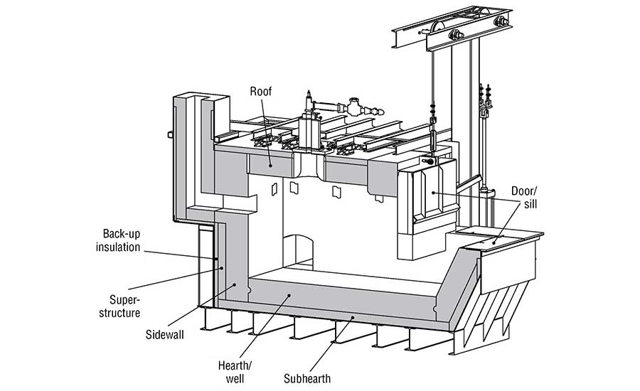
Figure 1. Schematic showing refractory lining in an aluminum furnace

Refractory Under Attack — Requirements for Melting Aluminum

The refractory lining in an aluminum furnace (Figure 1) must endure various chemical reactions that occur while the furnace is in operation. There are three separate regions to consider: above, below, and at the melt line. Above the melt line, the refractory must withstand attack from various alkali vapors. Alkali vapors can be produced from flux used in the aluminum and from the combustion products used to heat the furnace. Below the melt line, the refractory must withstand molten aluminum. At the melt line, the region commonly referred to as the bellyband area, there is a triple point where the refractory, atmosphere, and aluminum interact.

The refractory below the melt line comes in direct contact with liquid aluminum when the furnace is in operation. This contact can create a chemical reaction zone where oxides on the surface of the refractory can be reduced, such as silica (SiO2) to form silicon. Conversely, aluminum can penetrate into the refractory lining either through the same redox reactions or through infiltration due to capillary forces.

Aluminum forms corundum (Al2O3) when it oxidizes. This results in a change of the crystal structure from face-centered cubic to hexagonal, which causes a significant volume expansion. When corundum is formed inside the refractory lining, the change in volume creates cracks, which lead to more infiltration and more cracks until the refractory lining ultimately fails.

Wetting the Refractory

One method for reducing the reaction zone is to prevent the aluminum from “wetting” the refractory (see Figure 2). A liquid’s ability to “wet” a surface is defined by the contact angle of the liquid. When the contact angle between the liquid and the surface is greater than 90 degrees, then the liquid is said to wet the surface. When the contact angle is less than 90 degrees, the liquid does not wet the surface. A liquid that does not wet the surface is analogous to water beading on a car that has been freshly waxed. When aluminum does not wet a refractory, it is not able to react with the refractory and is not able to penetrate the lining.
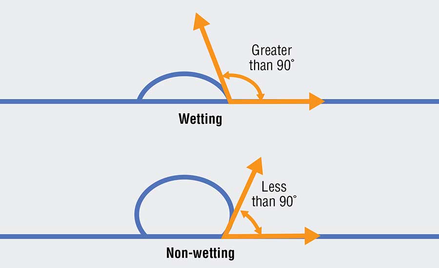
Figure 2. Contact angle of the liquid demonstrating wetting vs. non-wetting

Various additives can be used to reduce aluminum’s tendency to wet a refractory. Some of the most used additives include barium, boron, or fluoride. They modify the surface chemistry of the refractory and reduce aluminum’s ability to react and penetrate. Using additives such as these greatly extends the effective service life of a refractory lining.

While non-wetting additives can be beneficial to extending the service life in areas where there is contact with molten aluminum, there are no benefits when not in aluminum contact. They do not protect from alkali attacks above the melt line. They do not enhance the abrasion resistance of the material. They do not improve the thermal shock resistance of the material. Furthermore, these additives are volatile. When exposed to temperatures above 1700°F (927°C), they begin to lose their effectiveness because they chemically react with other materials in the refractory and change. The additives can also be costly, which raises the price of the refractory compared to one with the same composition but without the additive.

The presence of non-wetting additives can have some negative effects on a refractory. Tests have shown that a 1% addition of a fluoride additive in a conventional castable can reduce the hot modulus of rupture (HMOR) by as much as 30% at 2000°F (1093°C). The effect can be even more significant in a low-cement castable. The loss in hot strength is likely attributed to the formation of a glassy phase induced by the additive. Fluoride and boron are both well-known glass formers and will form a glassy phase at the grain boundaries at high temperatures, which reduces the bond strength between individual grains and the overall strength of the bulk material.
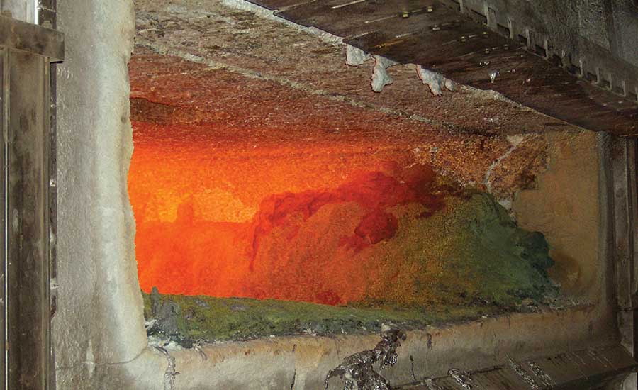
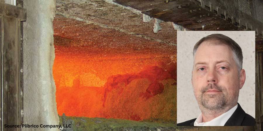
Figure 3. Refractory lining

Balancing Refractory Properties

The advantages and disadvantages of a refractory material should be considered when selecting materials for an aluminum furnace. The sidewalls of a furnace all come in direct contact with molten aluminum.

The upper sidewalls must be scraped to remove aluminum that splashes up to prevent corundum growth. The refractory selected for its sidewalls should be abrasion resistant to protect from mechanical scraping and non-wetting to protect from corundum growth. The hearth and well are submerged in aluminum, but they do not see the same level of abrasion as the sidewalls. The sub-hearth may see some molten aluminum but must also provide support, so a strong, non-wetting refractory should be used.

The door and sill will experience temperature fluctuations every time the door is opened, and they will be exposed to abrasion as the furnace is charged. Materials that are resistant to thermal shock and abrasion should be selected. The roof and superstructure need to be strong and resistant to alkali vapors. Backup insulation should be selected to reduce heat loss, but it should be of a composition that has moderate resistance to molten aluminum in case of refractory failure at the hot face.

In all these zones, the operating conditions of the specific furnace must be considered, and the balance of properties must be adjusted case-by-case. The primary failure modes must be identified, and materials should then be adjusted accordingly.

The Key to Refractory Selection

The operating conditions in an aluminum furnace require a refractory lining with different benefits in different zones. At the furnace door, the refractory can experience drastic fluctuations in temperature that can cause cracking. The upper sidewalls will develop scale that has to be scraped off, so the refractory needs to be abrasion resistant.

The lower sidewalls come in direct contact with molten aluminum and need to resist chemical attacks and aluminum penetration to avoid corundum growth. Finding a cost-effective refractory that can meet all these requirements is very difficult, but it can be done with sufficient research. Careful material selection that considers the needs and operating conditions of a particular furnace is important for maximizing the service life of a refractory lining.

About the Author:

Roger M. Smith
Director of Technical Services
Plibrico Company, LLC
Source: Plibrico

Roger Smith is a seasoned professional in the refractory industry. With a master’s degree in Ceramic Engineering from the University of Missouri – Rolla, Roger has over 15 years of experience in the processing, development, and quality assurance of both traditional and advanced ceramics. He has a proven track record in developing innovative ceramic formulations, scaling up processes for commercial production, and optimizing manufacturing operations.

For more information: Visit www.plibrico.com.

This article was initially published in Industrial Heating. All content here presented is original from the author.


Maintenance Message: Extending the Service Life of Refractory Linings Read More »

Stainless Corrosion


I’m starting to see Cybertrucks out in the wild more, so I decided to talk about stainless corrosion for #MetallurgyMonday. (If you don’t know what #MetallurgyMonday is, it is a weekly educational post on metallurgy topics that I’ve been writing on LinkedIn for the past two years.)

First a little up front. I’m not a fan of the aesthetics of the Tesla Cybertruck. Plus, we need about twice the load capacity for our work purposes since Skuld actually uses our truck as a truck.

More to the point, stainless steel is not rust proof. It is corrosion resistant and will rust in a lot of circumstances. 

To understand why, we need to understand what prevents corrosion in the first place. The key elements are chromium and nickel. Chromium reacts with oxygen to create a thin layer of chromium oxide. This is on the surface and blocks further oxidizing of the underlying layers. Meanwhile, the nickel enhances the corrosion resistance. It also makes the material more formable and weldable.

The short story is that if the chromium oxide layer gets compromised, stainless steel will corrode.

Improper heat treating can also contribute to stress corrosion cracking.

Sarah Jordan
  1. Pitting corrosion: If you have a scratch or a pit, this can damage the protective film, and then corrosion begins. It’s worse in environments with chloride ions, such as seawater or pool water. Chlorides break down the passive layer, leading to rapid and severe corrosion in small areas.
  2. Crevice corrosion: This occurs when two objects come together, especially things like fasteners or where there is a gasket. Inside the crevice you will have a lack of oxygen. The lack of oxygen prevents the reformation of the protective chromium oxide layer. Once corrosion gets started, it can get very severe by propagating in the crevice.
  3. Stress corrosion cracking (SCC): Corrosion is made worse where there is a combined effect of tensile stress and a corrosive environment. It typically affects stainless steel used in structural applications that are exposed to chloride or sulfides. SCC can cause sudden and catastrophic failure of the metal structure.
  4. Galvanic corrosion: Galvanic corrosion happens when two metals are put together. One of them almost always wants to preferentially corrode. The one that corrodes is the one that is higher on the galvanic series. 
  5. Intergranular corrosion (IGC): Sometimes this is called intergranular attack (IGA). In this case, corrosion occurs preferentially at grain boundaries. This can occur in stainless if the grain boundaries get depleted of chromium because a minimum amount is needed to ensure the passive film can form to protect the metal. When this occurs, there can also be localized galvanic corrosion.
  6. Composition variation: If the composition has segregation, then there are some areas that have less of the corrosion-helping elements. And on top of that, galvanic corrosion can start happening within the material.

What does all of this have to do with heat treating? Improper heat treating can contribute to corrosion.

For instance, intergranular corrosion can be caused if the material is exposed to 842–1562°F (450–850°C) for too long as this will cause chromium carbide to form at the grain boundaries and deplete the chromium. This process is called “sensitization.” It is avoided by making sure quench rates are fast enough through the risky temperature range.

A somewhat similar situation can occur during heat treating if sigma phase forms in super duplex stainless steel. Sigma phase is an iron chromium phase which can also deplete the chromium.

Improper heat treating can also contribute to stress corrosion cracking. When material is quenched, it can cause residual stresses that, if not relieved, can become an issue.

Corrosion in stainless steel can often be traced to improper heat treatment. When stainless steel is heated between 842–1562°F (450–850°C), chromium carbides can form at the grain boundaries, depleting the surrounding areas of chromium and making them susceptible to corrosion.

All of this to say, things like the Cybertruck (or for that matter stainless fridges and appliances) can be prone to corrosion since they are exposed to a lot of abuse and aggressive environments. It is critical to ensure they are properly manufactured, including good heat treating practices. It is also critical to provide them with proper maintenance to keep the corrosion resistance and appearance lasting as long as possible.

About the Author:

Sarah Jordan
Founder & CEO
Skuld, LLC
Source: Author

Sarah Jordan is an accomplished metallurgical engineer and entrepreneur. She received a bachelor’s of science and master’s of science in this discipline from The Ohio State University and has been pursuing a PhD in Metallurgical Engineering from WPI. Skuld is a certified WOSB and EDWOSB startup focused on 3D printing, advanced manufacturing, and advanced materials.


For more information, contact Sarah at her LinkedIn profile: Sarah Jordan | LinkedIn.


Find Heat Treating Products And Services When You Search On Heat Treat Buyers Guide.Com

Stainless Corrosion Read More »

Dual Chamber Vacuum Furnaces vs. Single Chamber Vacuum Furnaces — An Energy Perspective

The need to understand how certain furnace designs operate comes at a time when heat treaters are weighing each energy cost and benefit of their systems and processes. Read on for a quick summary on how dual chamber furnaces preserve energy.


On April 17-19, 2024, TAV VACUUM FURNACES provided a speaker at the 4th MCHTSE (Mediterranean Conference on Heat Treatment and Surface Engineering). The speech focused on the energy aspects of vacuum heat treatment, a subject towards which all of us within the industry need to pay attention for reducing the carbon emissions aiming at a zero net emissions future.

We have already analyzed the essential role that vacuum furnaces will play in this transition, with a focus on the optimization of energy consumption in our previous article. With this new presentation, we wanted to emphasize how selecting the right vacuum furnace configuration for specific processes may impact the energy required to perform such process. For doing so, we compared two different furnace designs — single chamber vs. dual chamber vacuum furnaces — detailing all of the components’ energy consumption for a specific process.

TAV DC4, dual chamber vacuum furnace for low pressure carburizing and gas quenching
Source: TAV VACUUM FURNACES

As a sneak peek into our presentation, we will summarize below how the main features of the two vacuum furnaces design are affecting their energy performance.

Let’s start by introducing the protagonist of our comparison: a single chamber, graphite insulated vacuum furnace, model TAV H4, and a dual chamber furnace TAV DC4, both having useful volume 400 x 400 x 600 mm (16” x 16” x 24”) (w x h x d).

In a single chamber vacuum furnace, like the TAV H4, the entire process is carried out with the load inside the furnace hot zone. This represents a highly flexible configuration that can perform complex heat treatment recipes with a multiple sequence of heating and cooling stages and to precisely control the temperature gradients at each stage.

Configuration of the TAV DC4 dual chamber vacuum furnace
Source: TAV VACUUM FURNACES

Alternatively, a dual chamber vacuum furnace, like the TAV DC4, is equipped with a cold chamber, separated from the hot zone, dedicated for quenching. Despite the greater complexity of this type of vacuum furnace, the dual chamber configuration allows for several benefits.

First, in dual chamber furnaces, the graphite insulated hot chamber is never exposed to ambient air during loading and unloading of the furnace; for this reason, the hot chamber may be pre-heated at the treatment temperature (or at a lower temperature, to control the heating gradient). But in single chamber vacuum furnaces, the hot zone must always be loaded and unloaded at room temperature to avoid damages due to heat exposure of graphite to oxygen.

Because dual chamber furnaces have more controlled heating, this will result in both faster heating cycles and lower energy consumption, as a substantial amount of energy is required to heat up the furnace hot zone. This advantage obviously will be more relevant in terms of energy savings the shorter the time is between subsequent heat treatments.

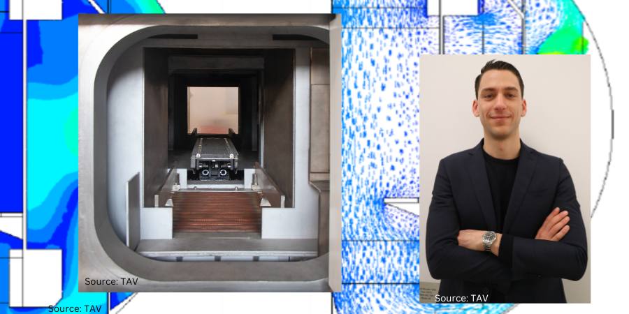
View of the cold chamber of the TAV DC4 dual chamber vacuum furnace
Source: TAV VACUUM FURNACES

Secondly, since the quenching phase is performed in a separated chamber, the hot zone insulation can be improved in dual chamber vacuum furnaces by increasing the thickness of the graphite board without compromising cooling performance. This translates into a significantly lower heat dissipation, to the extent that at 2012°F (1100°C) the power dissipation per surface unit (kW/m2) is reduced by 25% compared to an equivalent single chamber vacuum furnace.

Additionally, quenching in a dedicated cold chamber allows to obtain higher heat transfer coefficients and higher cooling rates compared to a single chamber vacuum furnace. Since the cold chamber is dedicated solely to the quenching phase, it can be designed for optimizing the cooling gas flow only without the need to accommodate all the components required for heating. All things considered, the heat transfer coefficient achievable in the TAV DC4 can be, all other things being equal, even 50% higher compared to a single chamber vacuum furnace. Secondly, since the cold chamber remains at room temperature throughout the whole process, only the load and loading fixtures need to be cooled down; as a result, the amount of heat that needs to be dissipated is significantly less compared to the single chamber counterpart.

CFD simulation showing a study on the cooling gas speed in a section of the cooling chamber for the TAV DC4 dual chamber vacuum furnace
Source: TAV VACUUM FURNACES

For heat treatments requiring high cooling rates, it is possible to process significantly higher loads on the dual chamber furnace compared to the single chamber model; translated into numbers, the dual chamber model can effectively quench as much as double processable in a single chamber furnace, depending on the alloy grade, load configuration and overall process. The savings in terms of energy consumption per unit load (kWh/kg) achievable in the dual chamber furnace for such processes can be as high as 50% compared to the single chamber furnace.

In the end, the aim of the speech was to highlight how the energy efficiency of vacuum furnaces is highly dependent on the machine-process combination. Choosing the right vacuum furnace configuration for a specific application, instead of relying solely on standardised solutions, will improve significantly the energy efficiency of the heat treatment process and drive the return on investment.

About the Author

Giorgio Valseccchi
R&D Manager
TAV VACUUM FURNACES

Giogio Valsecchi has been with the company TAV VACUUM FURNACES for nearly 4 years, after having studied mechanical engineering at Politecnico di Milano. 

For more information: Contact Giorgio at info@tav-vacuumfurnaces.com.


Find Heat Treating Products And Services When You Search On Heat Treat Buyers Guide.Com


Dual Chamber Vacuum Furnaces vs. Single Chamber Vacuum Furnaces — An Energy Perspective Read More »