HARDENING TECHNICAL CONTENT

Improving Hardening and Introducing Innovation for In-House Heat Treat

Digital tools lead the way in vacuum hardening operations to ensure energy efficiency and processing repeatability. In this Technical Tuesday installment, Paulo Duarte, project manager at Metalsolvus, examines various advantages of wrought versus cast alloys in heat treat operations.

This informative piece was first released in Heat Treat Today's March 2025 Aerospace print edition.


Vacuum hardening has been the chosen process for hardening tools used in plastic injection, die casting, and metal sheet stamping over the past few decades. Although widely used and accepted, there is still room for improvement in tool performance through quality driven procedures. By employing easy methods of measurement, study, and testing, it is possible to enhance part integrity and mechanical properties, while simultaneously reducing heat treatment time and energy consumption. Advanced metallurgical analyses of heat treatment cycles and equipment can introduce better tools on the market, as well as provide time and cost saving heat treatments.

Basics of Vacuum Hardening

Figure 1. Cooling parts in vacuum hardening furnaces — inert gas injection on the hot chamber during cooling

In vacuum hardening furnaces, temperature and time are carefully controlled at specific load locations to ensure optimal hardening. Optimal practices focus on heating and soaking the metal parts during heat treatment. The controlled introduction of vacuum and inert gases during the process ensures the right protective atmosphere for treatment, resulting in steel that is mainly free from oxidation and decarburization. This preserves the surface integrity of the tools.

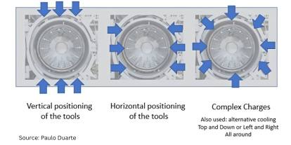
Cooling is achieved through the injection of an inert gas into the heating chamber, with controlled pressure and adequate recirculation between the heat exchanger and the hot zone (Figure 1). Different gas injection directions are utilized depending on the load being treated, ensuring optimal cooling.

Hardening of Large Tools

Figure 2. Large molds positioned inside the vacuum hardening furnace, two parallel cavities

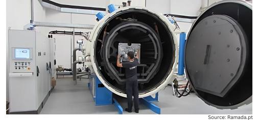
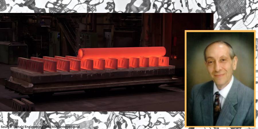
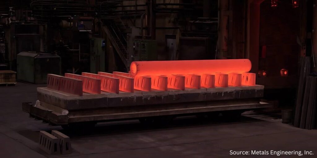
Heating and quenching large tools is one of the most challenging situations for vacuum hardening, as temperature control and part microstructure integrity are more difficult to obtain, which affects part quality. Large tools, typically made of hot work tool steels, are hardened in large furnaces. To minimize deformation, parts are preferably positioned vertically inside the furnace (Figure 2).

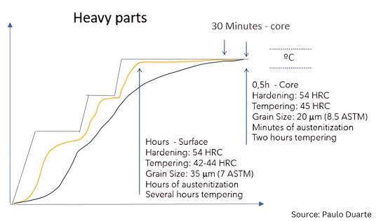
Surface soaking times for big tools can significantly exceed
standard austenitization and tempering times due to thermal gradients existing within the parts. Mold cores usually achieve the right soaking and tempering recommendation through accurate temperature control, monitored by well-positioned core thermocouples. A tool’s microstructure and performance will depend heavily on geometry, size, and temperature uniformity achieved during treatment. See Figure 3 for the core and surface typical hardening cycles for large tools.

Figure 3. Heating and soaking cycle for the hardening of large tools (“Heat Treatment of a AISI H11 Premium Hot-Work Tool Steel”)

The cooling phase is crucial in determining the final properties of both the surface and core of the tool. Higher gas injection pressures result in faster cooling and increased toughness, but this also introduces greater deformation risks, when directly cooled from austenitization temperature, so martempering done at low pressures is usually required.

Balancing cooling pressure is one of the most secret topics in vacuum hardening. With a variety of parameters and procedures used among heat treaters, measuring and testing is essential for achieving consistent quality for better controlling the hardening process and attaining the best part quality.

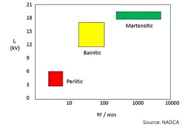
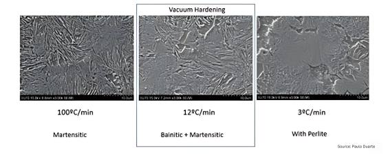
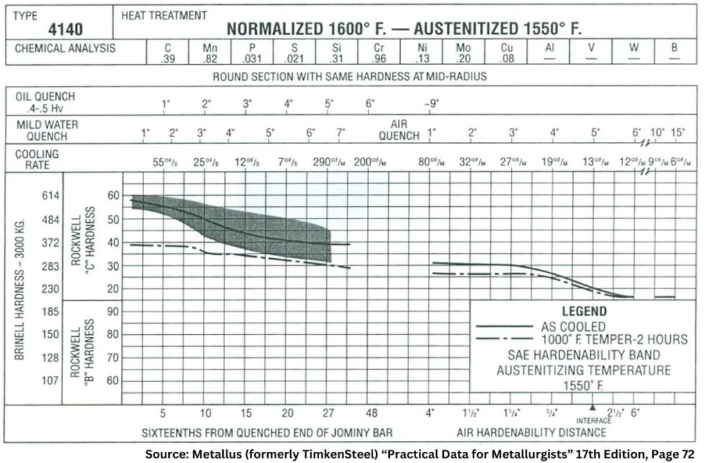
The use of higher or lower inert gas pressures directly affects the cooling rate, making it faster or slower, respectively. Regulating the gas injection pressure during the cooling phase significantly impacts the material’s toughness, even when cooling occurs within the bainitic-martensitic domain commonly observed in vacuum hardening practices. Faster cooling leads to finer microstructures, which in turn results in tougher materials. However, fully martensitic microstructures are rarely achieved in industrial vacuum hardening furnaces and are typically limited to smaller loads composed of small parts. In larger parts, the risk of pearlite formation increases, especially when cooling rates fall around 3°C/min (5°F/min) at the core, as illustrated in Figures 4 and 5.

In industrial heat treatments of large tools, accurately monitoring core temperature is challenging, as it is difficult to position a thermocouple hole exactly at the innermost location or a nearby region. This makes it harder to control the hardening process and prevent pearlite formation. Therefore, studying the process to establish effective control measures is essential for achieving the highest possible
quality.

Figure 6. Mold temperature gradients during vacuum hardening: a) FEM mesh, b) gradients during heating at lower temperatures, c) gradients at the last pre-heating steps, and d) gradients during austenitization from Maia et al. “Study of Heating Stage of Big Dimension Steel Parts Hardening”; e) gradients during mold cooling from Pinho et al. “Modelling and Simulation of Vacuum Hardening of Tool Steels”

Heat treatment simulation simplifies this task by allowing the hardening process to be predicted, with thermal gradients estimated and compensated through furnace control parameter adjustments. Figure 6 presents a real case study, where the temperature distribution inside a large mold was fully characterized during the entire heat treatment cycle using FEM (finite element method) simulation and validated through actual thermocouple measurements. FEM simulation, as a proven and highly effective technique for predicting heat treatment cycles, enables heat treaters to implement optimized, computer-supported heat treatment practices.

Vacuum Hardening Standard Block Size and Cycle Forecast

When working with loads composed of small to medium-sized parts, the core temperature of the load can be monitored using dummy standard blocks. These blocks have a central hole to accommodate the thermocouple used to control the heat treatment cycle. The dummy block should be selected to closely match the size of the largest part in the load. However, in commercial heat treatment settings, part sizes can vary widely, making it difficult to maintain a comprehensive set of dummy blocks that represents all possible heat treatment scenarios.

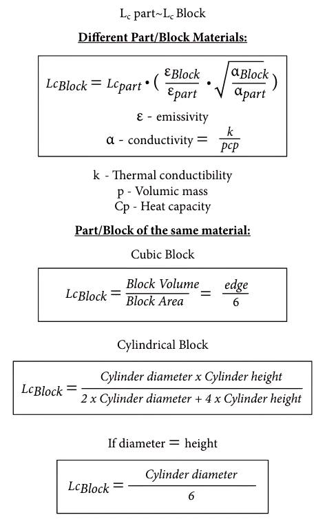
Once again, simulation proves valuable in helping heat treaters gather useful data to anticipate the heat treatment cycle and determine the appropriate range of dummy blocks to have available on the shop floor. The procedure for selecting the dummy block range and forecasting the corresponding heat treatment times is outlined in the following equations. Ideally, the standard block should be made from the same material as the largest part in the load. If the materials differ, the characteristic length of the block can be calculated using the first of the equations to the right.

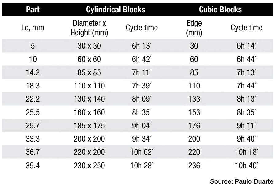
Table 1 lists a range of proposed dummy block sizes to be used for monitoring the load temperature during heat treatment. The time to end of soaking at higher temperature is also given by Table 1 for a typical 600 x 600 x 900 mm hardening furnace. Times were obtained by FEM simulation and can be used to forecast the end of austenitization in a hardening process of each dummy block.

Table 1. Proposed dimensional distribution range for cubic and cylindrical standard blocks and expected cycle times in a typical 600 x 600 x 900 mm hardening furnace (data from Figueiredo et al., “Study of a Methodology for Selecting Standard Blocks for Hardening Heat Treatments”)

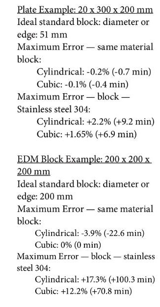
The simulated times were validated by using real parts temperature measurement by thermocouples. These were the calculated errors based on simulation and heat treat validation trial:

Optimizing the Vacuum Hardening of Tools

Figure 7. Effect of selecting different temperature (ΔT) range for starting to control the isothermal stage time. a) ΔT criteria and respective cycle time reduction; b) surface mechanical properties obtained by using different ΔT; and c) core properties after tempering at different ΔT range (Miranda et al., “Heat Treatment of a AISI H11 Premium Hot-Work Tool Steel,” MSC)

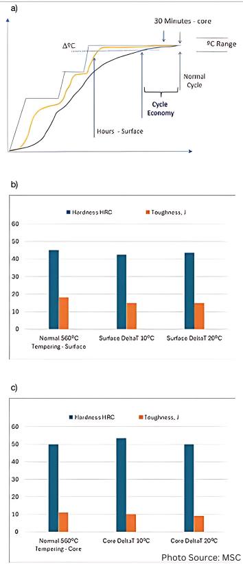
FEM simulation can also be used to optimize the heat treatment process, but metallurgical testing remains crucial for providing reliable insights into safely reducing cycle time and energy consumption. Typically, for setting the isothermal stage time, a tolerance of -5°C relative to the temperature setpoint is used, leading to savings in both heat treatment duration and power consumption, as shown in Figure 7a. However, Figure 7b demonstrates that higher tolerance values (ΔT) can be considered. Tolerances of up to -10°C or even -20°C can be applied for controlling the soaking time without significantly affecting the hardness and toughness of the parts. Naturally, these results depend on the desired setpoints for the isothermal stages, but Figure 7c reflects the worst-case scenario for ΔT, referring to the use of lower austenitizing and tempering temperatures commonly applied in the hardening of hot-work tool steels.

Future Trends of Vacuum Hardening

Innovations like digitalization, automation, and resource reduction, as part of Industry 5.0 initiatives, are expected to drive advancements in heat treatment processes. Long martempering, a heat treatment under development for hardening hot-work tool steels, shows promise as an alternative to traditional quenching and tempering. This process offers a balance of high hardness and toughness in significantly less time, providing energy savings and faster turnaround.

New Vacuum Hardening Process — Long Martempering

Figure 8. New long martempering heat treatment cycle: AISI H13 premium toughness for two different long martempering temperatures (“Study of The Bainitic Transformation of H13 Premium Steel”)

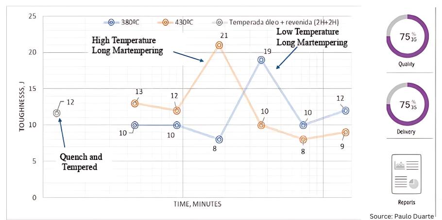
Long martempering is a heat treatment under development that can be used to harden hot-work tool steels. Long martempering is a process somewhat similar to austempering but is applied to steels rather than cast irons. Performed at temperatures within the martempering range, long martempering corresponds to an interrupted bainitic heat treatment with a specific process window (Figure 8) where high toughness is achieved at hardness levels exceeding those obtained through traditional quenching and tempering. Table 2 lists the mechanical properties attained for 5Cr hot-work premium tool steels.

Table 2. Mechanical properties of the new hardening process — long martempering

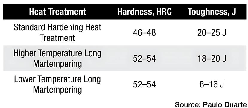
The transformation during long martempering is not yet fully characterized in terms of microstructure, however, curved needles of bainitic ferrite are observed without carbide precipitation. This phenomenon is generally not associated with steel but rather with ausferrite in cast irons. Nonetheless, it is evident in at least H11 and H13 premium steel grades. This one day martempering treatment could potentially replace the traditional two- to three-day heat treatment cycle for large tools, offering significantly faster lead times and reduced energy consumption. Moreover, the mechanical properties achieved through long martempering are notable, as high levels of both hardness and toughness are obtained simultaneously, as demonstrated in Table 2.

Industry 5.0

Figure 9. Heat treatment plant supervision solution

The integration of heat treatment equipment with management software enhances furnace utilization, quality control systems, and maintenance practices. Industry 5.0 can be implemented in heat treatment plants through the connection of databases that collect inputs from furnaces (e.g., temperature, time, pressure, heating elements, and auxiliary equipment performance) and production data (e.g., batch numbers, order details, operator information, cycle setup, and load weight). This data is analyzed by software to generate valuable insights for plant management, process optimization, predictive maintenance, and quality control.

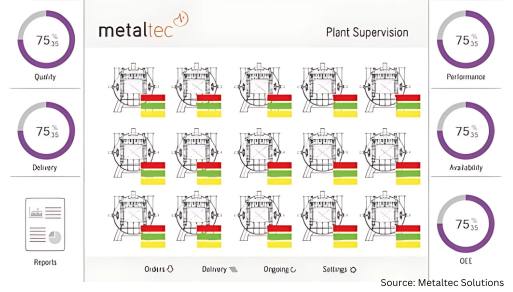
A supervision interface for a 5.0 solution can monitor furnaces and control them remotely in real time (Figure 9). Operators receive updates on tasks, alerts, and production schedules. Additionally, plant productivity, efficiency, and maintenance can be tracked through the same supervision software, whether on site or remote. Automatic reporting is also possible, enabling the approval or rejection of cycles based on criteria that are not typically used in heat treatment plants. This not only improves quality but also facilitates process optimization and cost reduction.

Conclusion

Acquiring a full understanding of furnaces in operation through data measurement and analysis allows full control over the heat treatment process. This facilitates process development, enabling cycle optimization and improvement in part quality. Additionally, testing and simulation practices can lead to cost reduction and shorter lead times.

The introduction of long martempering and Industry 5.0 will significantly enhance heat treatment processes, leading to improved delivery times and reduced operational risks. Automation and digitalization bring more data to the shop floor, improving plant management and resulting in greater efficiency, higher quality parts, and simplified task execution.

Finally, current personnel are busy with routine operations that are based on long established practices and may be limiting opportunities for innovation. Therefore, new teams or external consultants can be leveraged to focus on designing, studying, testing, and implementing each new heat treatment solution.

References

Fernandes, José, Laura Ribeiro, and Paulo Duarte. “Study of the Bainitic Transformation of H13 Premium Steel.” MSC thesis, Faculty of Engineering of Oporto University, 2021.

Figueiredo, Ana, Paulo Coelho, José Marafona, and Paulo Duarte. “Study of a Methodology for Selecting Standard Blocks for Hardening Heat Treatments.” MSC thesis, Faculty of Engineering of Oporto University, 2022.

Kind & Co. “Vacuum Hardening with Highest Levels of Precision.” Accessed January 30, 2025. https://www.kind-co.de/en/company/technologies/vacuum-hardening.html.

Maia, Pedro, Paulo Coelho, José Marafona, and Paulo Duarte. “Study of Heating Stage of Big Dimensions Steel Parts Hardening.” MSC thesis, Faculty of Engineering of Oporto University, 2013.

Metaltec Solutions. “Brochure Presentation.” Accessed January 30, 2025. https://www.metalsolvus.pt/en/wp-content/uploads/2019/01/plant-supervision-brochure-V3.pdf.

Miranda, Isabel, Laura Ribeiro, and Paulo Duarte. “Heat Treatment of AISI H11 Premium Hot-Work Tool Steel.” MSC thesis, Faculty of Engineering of Oporto University, 2024.

Pinho, José Eduardo, Gil Andrade Campos, and Paulo Duarte. “Modelling and Simulation of Vacuum Hardening of Tool Steels.” MSC thesis, Aveiro University, 2017.

Ramada. “New Hardening Furnace up to 4 Tons.” Accessed January 30, 2025. https://www.ramada.pt/pt/media/noticias/novo-forno-de-tempera-vacuo---ate-4-tons-.html.

Schmetz. “Schmetz Heat Treatment Furnaces.” Accessed January 30, 2025. https://edelmetal.com.tr/en/heat-treatment-furnaces.

Schmetz. Sketch of the Cooling Process in the Vacuum Hardening Furnace: Schmetz Commercial Proposals Drawing – Metalsolvus Training Courses Documentation.

Seco/Warwick. Vector 3D Hardening Furnace Commercial Brochure.

Solar Manufacturing. “Solar Vacuum Hardening Furnace.” Accessed January 30, https://solarmfg.com/vacuum-furnaces-horizontal-iq-vacuum-furnaces.

Wallace, J.F., W. Roberts, and E. Hakulinen. “Influence of Cooling Rate on the Microstructure and Toughness of Premium Grade H13 Die Steels.” Transactions of the 15th NADCA Congress (1989).

About The Author:

Paulo Duarte, project manager at Metalsolvus, is a researcher and consultant on heat treat technologies. His education and expertise in metallurgy has culminated in several articles and patents. He was a former technical manager within bohler-uddeholm group for the Portuguese market and heat treatment manager with the same group. Currently, Paulo focus on helping heat treaters by providing innovative, more efficient, and profitable heat treatment services to companies.

For more information: Contact Paulo Duarte at paulo.duarte@metalsolvus.pt.


Improving Hardening and Introducing Innovation for In-House Heat Treat Read More »

Why Normalize, and Is a ‘Still Air’ Cool Really Important? Part 2

The Heat Treat Doctor® has returned to offer sage advice to Heat Treat Today readers and to answer your questions about heat treating, brazing, sintering, and other types of thermal treatments as well as questions on metallurgy, equipment, and process-related issues.

This informative piece was first released in Heat Treat Today’s March 2025 Aerospace Heat Treating print edition.


Last time (Air & Atmosphere Heat Treating, February 2025) we addressed the question of why normalizing is necessary. Here we look at the importance of a “still air” cool on the final result. Let’s learn more.

What Is a “Still Air” Cool?

Contact us with your Reader Feedback!

As we learned last month, the term “cooling in air” is associated with normalizing but poorly defined in the literature or in practice, either in terms of cooling rate or microstructural outcome. This lack of specificity has resulted not only in many different interpretations of what is needed, but in a great deal of variability in the final part microstructure.

By way of example, this writer has on multiple occasions asked what changes are made to car bottom furnace cycles where cars are pulled outside of the plant for “air cooling” (Figure 1). Questions such as, is the furnace opened and the car pulled out in inclement weather? And, is this practice done on a particularly windy day, or in a rain or snowstorm or when the temperature is below zero? An all-too-common response is, “Only if it isn’t raining ‘too hard’ or snowing ‘too much’; then, we wait a while.” No wonder part microstructures are often found to vary from part to part and load to load!

Most heat treaters agree, however, that normalizing is optimized by a cooling in “still air.” This term also hasn’t been clearly defined, but it will be here based on both an extensive survey of the literature and the most common heat treat practices. In Vacuum Heat Treatment, Volume II, I define a still air cool as: “Cooling at a rate of 40°F (22°C) per minute … to 1100°F (593°C) and then at a rate of 15°F–25°F (8°C–14°C) per minute from 1100°F (593°C) to 300°F (150°C). Any cooling rate can be used below 300°F (150°C).”

Typical car bottom normalizing furnace opening to the outside environment

In addition, many consider nitrogen gas quenching in a vacuum furnace at 1–2 bar pressure to be equivalent to a still air cool. But again, so many factors are involved that only properly positioned workload thermocouples can confirm the above cooling rates are being achieved.

Also, many use the term “air cooling” to differentiate the process from “air quenching,” “controlled cooling,” and “fan cooling.”

Recall from the previous installment of this column that any ambiguity with respect to cooling rate ought to be defined in engineering specifications and/or heat treat instructions so that the desired outcome of the process can be firmly established.

From the literature, several important observations will serve as cautionary reminders. In STEELS, George Krauss points out that: “Air cooling associated with normalizing produces a range of cooling rates depending on section size [and to some extent, load mass]. Heavier sections air cool at much lower cooling rates than do light sections because of the added time required for thermal conductivity to lower temperatures of central portions of the workpiece.”

George Totten’s work in Steel Heat Treatment indicates: “Cooling … usually occurs in air, and the actual cooling rate depends on the mass which is cooled.” He goes on to state:

After metalworking, forgings and rolled products are often given an annealing or normalizing heat treatment to reduce hardness so that the steel may be in the best condition for machining. These processes also reduce residual stress in the steel. Annealing and normalizing are terms used interchangeably, but they do have specific meaning. Both terms imply heating the steel above the transformation range. The difference lies in the cooling method. Annealing requires a slow [furnace] cooling rate, whereas normalized parts are cooled faster in still, room-temperature air. Annealing can be a lengthy process but produces relatively consistent results, where normalizing is much faster (and therefore favored from a cost point of view) but can lead to variable results depending on the position of the part in the batch and the variation of the section thickness in the part that is stress-relieved.

In “The Importance of Normalizing,” this writer offers the following caution: “It is important to remember that the mass of the part or the workload can have a significant influence on the cooling rate and thus on the resulting microstructure.”

Finally, Krauss again observes: “The British Steel Corporation atlas for cooling transformation (Ref. 13.7) establishes directly for many steels the effect of section size on microstructures produced by air cooling.” (Note: Interpretation of continuous cooling transformation (CCT) curves will be the subject of a future “Ask The Heat Treat Doctor” column.)

Since hardness is one of the most commonly used criteria to determine if a heat treat process has been successful, it should also be noted that one can usually predict the hardness of a properly normalized part by looking at the J40 value when Jominy data is available.

The Metallus (formerly TimkenSteel) “Practical Data for Metallurgists” provides an example of the type of data available to metallurgists and engineers to help define a required cooling rate for normalizing (Figure 2).

All literature references to normalizing agree (or infer) that the resultant microstructure produced plays a significant role in both the properties developed and their impact on subsequent operations.

Figure 2. Combined hardenability chart for normalized and austenitized SAE 4140 steel showing approximate still air cooling rates and resultant hardness (data based on a thermocouple located in the center of the bar diameter indicated)

Final Thoughts — The State of the Industry

It is all too common within the industry for some companies who wish to have normalizing performed on their products to specify only a hardness range on the engineering drawing or purchase order callout that is given to the heat treater.

Industry normalizing practice here in North America varies considerably from company to company. Normalizing instructions are sometimes, but not often enough, provided on either purchase orders, engineering drawings, or in specifications (industry standards or company-specific documents). These instructions range from, in the case of certain weldments, absolutely nothing (i.e., no hardness, microstructure, or mechanical properties) to referencing industry specifications (e.g., AMS2759/1) or specifying complete metallurgical and mechanical testing including hardness and microstructure.

Most commercial heat treaters often perform normalizing to client or industry specifications provided to them. Others prefer so-called “flow down” instructions in which the process recipe is provided to them. It is a common (and mistaken) belief that this removes the obligation of achieving a given set of mechanical or metallurgical properties even if they are called out by specification, drawing, or purchase order.

Also, the final mechanical properties that result from normalizing are seldom verified by the heat treater. Rather, a hardness value (or range) is reported, but hardness is not a fundamental material property, rather a composite value, one which is influenced by, for example, the yield strength, work hardening, true tensile strength, and modulus of elasticity of the material.

References

ASM International. “ASM Handbook, vol. 4, Heat Treating,” 1991.

ASM International. “ASM Handbook Volume 4A, Steel Heat Treating, Fundamentals and Processes,” 2013.

Chandler, Harry, ed. Heat Treater’s Guide: Practices and Procedures for Irons and Steels. 2nd ed, ASM International, 1995.

Grossman, M. A., and E. C. Bain. Principles of Heat Treatment, 5th ed, ASM International, 1935.

Herring, Daniel H. Atmosphere Heat Treatment, vol. I, BNP Media, 2014.

Herring, Daniel H. Atmosphere Heat Treatment, vol. II, BNP Media, 2015.

Herring, Daniel H. Vacuum Heat Treatment, vol. I, BNP Media, 2012.

Herring, Daniel H. Vacuum Heat Treatment, vol. II, BNP Media, 2016.

Herring, Daniel H. “The Importance of Normalizing,” Industrial Heating April 2008.

Krauss, George. STEELS: Heat Treatment and Processing Principles, ASM International, 1990. 463.

Krauss, George. STEELS: Processing, Structures, and Performance, ASM International, 2005.

Practical Data for Metallurgists, 17th ed. TimkenSteel, 2011

Totten, George E., ed. Steel Heat Treatment Handbook, vol. 2, 2nd ed., CRC Press, 2007.

About the Author

Dan Herring
“The Heat Treat Doctor”
The HERRING GROUP, Inc.

Dan Herring has been in the industry for over 50 years and has gained vast experience in fields that include materials science, engineering, metallurgy, new product research, and many other areas. He is the author of six books and over 700 technical articles.

For more information: Contact Dan at dherring@heat-treat-doctor.com.

For more information about Dan’s books: see his page at the Heat Treat Store.


Find Heat Treating Products And Services When You Search On Heat Treat Buyers Guide.Com


Why Normalize, and Is a ‘Still Air’ Cool Really Important? Part 2 Read More »

Why Normalize, and Is a ‘Still Air’ Cool Really Important? Part 1

The Heat Treat Doctor® has returned to offer sage advice to Heat Treat Today readers and to answer your questions about heat treating, brazing, sintering, and other types of thermal treatments as well as questions on metallurgy, equipment, and process-related issues.

This informative piece was first released in Heat Treat Today’s February 2025 Air/Atmosphere Furnace Systems print edition.


People often ask two fundamental questions related to normalizing. First, is it necessary? Second, just what and how important is a “still air” cool to the end result? Let’s learn more.

Why Normalize?

Contact us with your Reader Feedback!

Normalizing is typically performed for one or more of the following reasons:

  • To improve machinability
  • To improve dimensional stability
  • To produce a homogeneous microstructure
  • To reduce banding
  • To improve ductility
  • To modify and/or refine the grain structure
  • To provide a more consistent response when hardening or case hardening

For example, many gear blanks are normalized prior to machining so that during subsequent hardening or case hardening dimensional changes such as growth, shrinkage, or warpage will be better controlled.

Normalizing imparts hardness and strength to both cast iron and steel components. In addition, normalizing helps reduce internal stresses induced by such operations as forging, casting, machining, forming or welding. Normalizing also improves chemical non-homogeneity, improves response to heat treatment (e.g., hardening), and enhances dimensional stability by imparting into the component part a “thermal memory” for subsequent lower temperature processes. Parts that require maximum toughness and those subjected to impact are often normalized. When large cross sections are normalized, they are also tempered to further reduce stress and more closely control mechanical properties.

Large paper roll normalized in a car bottom furnace and cooled (due to its mass) using the assistance of a floor fan.

Soak periods for normalizing are typically one hour per inch of cross-sectional area but not less than two hours at temperature. It is important to remember that the mass of the part or the workload can have a significant influence on the cooling rate and thus on the final microstructure. Thin pieces cool faster and are harder after normalizing than thicker ones. By contrast, after furnace cooling in an annealing process, the hardness of the thin and thicker sections is usually about the same.

Micrograph of medium-carbon AISI/SAE 1040 steel showing ferrite grains (white etching constituent) and pearlite (dark etching constituent). Etched in 4% picral followed by 2% nital. (Bramfitt and Benscoter, 2002, p. 4. Reprinted with permission of ASM International. All rights reserved.)

When people think of normalizing, they often relate it to a microstructure consisting primarily of pearlite and ferrite. However, normalized microstructures can vary and combinations of ferrite, pearlite, bainite, and even martensite for a given alloy grade are not uncommon. The resultant microstructure depends on a multitude of factors including, but not limited to, material composition, part geometry, part section size, part mass, and cooling rate (affected by multiple factors). It is important to remember that the microstructure achieved by any given process sequence may or may not be desirable depending on the design and function of the component part.

The microstructures produced by normalizing can be predicted using appropriate continuous cooling transformation diagrams and this will be the subject of a subsequent “Ask The Heat Treat Doctor” column.

In this writer’s eyes, industry best practice would be to specify the desired microstructure, hardness, and mechanical properties resulting from the normalizing operation. Process parameters can then be established, and testing performed (initially and over time) to confirm/verify results.

In many cases, the failure of the normalizing process to achieve the desired outcome centers around the lack of specificity (e.g., engineering drawing requirements, metallurgical and mechanical property call outs, testing/verification practices, and quality assurance measures). Failure to specify the required microstructure and mechanical properties/characteristics can lead to assumptions on the part of the heat treater, which may or may not influence the end result.

“Normalizing is the heat treatment that is produced by austenitizing and air cooling, to produce uniform, fine ferrite/pearlite microstructures in steel … In light sections, especially in alloy hardenable steels, air cooling may be rapid enough to form bainite or martensite instead of ferrite and pearlite.”

What Is Normalizing?

The normalizing process is often characterized in the following way: “Properly normalized parts follow several simple guidelines, which include heating uniformly to temperature and to a temperature high enough to ensure complete transformation to austenite; soaking at austenitizing temperature long enough to achieve uniform temperature throughout the part mass; and cooling in a uniform manner, typically in still air” (Herring, 2014).

It is also important to remember that normalizing is a long-established heat treatment practice. As far back as 1935, Grossmann and Bain wrote:

Normalizing is the name applied to a heat treatment in which the steel is heated above its critical range (that is, heated to make it wholly austenitic) and is then allowed to cool in air.

Since this is one specific form of heat treatment, it will be realized that the structure and mechanical properties resulting from the normalizing treatment will depend not only on the precise composition of the steel but also on the precise way in which the cooling is carried out.

The term ‘normalizing’ is generally applied to any cooling ‘in air.’ But in reality, this may cover a wide range of cooling conditions, from a single small bar cooled in air (which is fairly rapid cooling) to that of a large number of forgings piled together on a forge shop floor … which is a rather slow cool, approaching an anneal. The resulting properties in the two cases are quite different.

In plain carbon steels and in steel having a small alloy content, the air-cooled (normalized) structure is usually pearlite and ferrite or pearlite alone … More rapid cooling gives fine pearlite, which is harder; slow cooling gives coarse pearlite, which is soft. In some few alloy steels, the normalized structure in part may be bainite.

The hardness of normalized steels will usually range from about 150 to 350 Brinell (10 to 35 Rockwell C), depending on the size of the piece, its composition and hardening characteristics.

Importance of Defining Cooling Rate

In 2005, Krauss underscored the importance of defining cooling rate when he wrote: “Air cooling associated with normalizing produces a range of cooling rates depending on section size [and to some extent, load mass]. Heavier sections [and large loads] air cool at much lower cooling rates than do light sections because of the added time required for thermal conductivity to lower temperatures of central portions of the workpiece.”

Microstructures Created by Normalizing

The microstructural constituents produced by normalizing for a particular steel grade can be ferrite, pearlite, bainite, or martensite. The desired microstructure from normalizing adds an important cautionary note, as addressed by Krauss in STEELS (1990 and 2005), namely: “Normalizing is the heat treatment that is produced by austenitizing and air cooling, to produce uniform, fine ferrite/pearlite microstructures in steel … In light sections, especially in alloy hardenable steels, air cooling may be rapid enough to form bainite or martensite instead of ferrite and pearlite.”

Next time: We define a “still air” cool and look at the state of normalizing in North America.

References

ASM International. “ASM Handbook, vol. 4, Heat Treating,” (1991): 35–41.

ASM International. “ASM Handbook Volume 4A, Steel Heat Treating, Fundamentals and Processes,” (2013): 280–288.

ASM International. “Metals Handbook, 8th ed., vol. 1, Properties and Selection of Metals,” (1961): 26.

ASM International. “Metals Handbook Desk Edition,” (1985): 28-11, 28-12.

Chandler, Harry, ed. Heat Treater’s Guide: Practices and Procedures for Irons and Steels. 2nd ed, ASM International, 1995.

Grossman, M. A., and E. C. Bain. Principles of Heat Treatment, 5th ed, ASM International, 1935, 197–198.

Herring, Daniel H. Atmosphere Heat Treatment, vol. I, BNP Media, 2014.

Herring, Daniel H. Atmosphere Heat Treatment, vol. II, BNP Media, 2015.

Herring, Daniel H. “The Importance of Normalizing,” Industrial Heating April 2008.

Krauss, George. STEELS: Heat Treatment and Processing Principles, ASM International, 1990. 463.

Krauss, George. STEELS: Processing, Structures, and Performance, ASM International, 2005. 253–256, 574.

Lyman, Taylor, ed. Metals Handbook, 1948 ed. ASM International, 1948. 643.

Practical Data for Metallurgists, 17th ed. TimkenSteel.

Totten, George E., ed. Steel Heat Treatment Handbook, vol. 2, 2nd ed., CRC Press, 2007. 612-613.

About the Author

Dan Herring
“The Heat Treat Doctor”
The HERRING GROUP, Inc.

Dan Herring has been in the industry for over 50 years and has gained vast experience in fields that include materials science, engineering, metallurgy, new product research, and many other areas. He is the author of six books and over 700 technical articles.

For more information: Contact Dan at dherring@heat-treat-doctor.com.

For more information about Dan’s books: see his page at the Heat Treat Store.


Find Heat Treating Products And Services When You Search On Heat Treat Buyers Guide.Com


Why Normalize, and Is a ‘Still Air’ Cool Really Important? Part 1 Read More »

Heat Treat Radio #115: Lunch & Learn: Decarbonization Part 2

In this episode of Heat Treat Radio, Doug Glenn and guest Michael Mouilleseaux, general manager at Erie Steel LTD, continue their discussion of case hardness, delving into the hardening ability of materials, focusing on case hardening and effective case depth. Michael explains the differences between total and effective case depth, the impact of core hardness, and the role of material chemistry. They also discuss practical applications for heat treaters, emphasizing the importance of understanding material properties.

Below, you can watch the video, listen to the podcast by clicking on the audio play button, or read an edited transcript.


The following transcript has been edited for your reading enjoyment.

The Influence of Core Hardness on Effective Case Depth Measurement (01:03)

Doug Glenn: Today we are going to talk about a pretty interesting topic, and some interesting terminology, that has to do with hardness and hardenability of metals. For people who are not metallurgists, this may seem like a strange topic because isn’t all metal hard?

But we are going to talk more in depth about hardness of metal, hardenability of metal, and effective case depth. What we want to do is get a run down on the influence of core hardness on effective case depth measurements.

Michael Mouilleseaux: We are going to get a little bit into the weeds today on some things specific to metallurgy.

Those who are involved in high volume production carburizing know that consistency of results is extremely important. It is not just important in that we have the process centered in that the results are that way, but ultimately it has something to do with the dimensional control.

Specifically with gears, if the output from the process is not consistent, then one of the things that is going to suffer is going to be the dimensions. So, we’re going to be talking about effective case depths today.

Effective Case Depth vs. Total Case Depth (02:23)

Effective case depth is a little bit different from total case depth. Total case depth is the total depth that carbon is diffused into a part. That is very much a function of time and temperature. And there are some nuances with grain size and alloy content, but it is essentially a time and temperature phenomena.

Effective case depth vs total case depth (02:59)

Effective case depth is a little bit different. If we look at this graph, the x axis is the distance to the surface, and the y axis is hardness in Rockwell C.

If you look at the green line, this is a micro hardness traverse of a carburized part. It tells us many things. If you look at the left-hand side of the line at .005 in depth, the hardness there is 60 Rockwell C. Then it diminishes as we go further into the part: 0.010, 0.020, 0.040, 0.050.

We get to the end of that line, and we see that is the core strength. The core is a function of the material hardenability.

So, what is the effective case depth? If we look at the second vertical blue line on the right, it says “Total Visual Case.” So that’s exactly what that is. If we were to look at this part and etch it — I am presupposing that everybody understands that we would section the part — we would mount it, we would polish it, and then we would look at it in the microscope at 100x. Then, we would see a darkened area, which would be the total depth of carbon diffusion into the part. That is not a function of the material grade; there are some nuances there.

But the effective case depth is a measurement. And in North America’s SAE Standard J423, we say that we measure the case effective depth to Rockwell C 50. The surface hardness is 60, we measure the hardness in increments, and when we reach this hardness the depth that hardness achieves is 50 Rockwell. That is the effective case depth. If we look at the core hardness on that part, we can see that on this particular sample it is somewhere between 45 and 50.

Finding Material Hardenability (05:17)

Hardenability band graph (14:26)

What causes this core hardness? It has to do with the hardenability of the material.

Here we are looking at an SAE chart J1268. It is for H band material for 4320, a common gear material. This tells us a lot. It has the chemistry on it, below that it has some information for approximate diameters, and then it has, on the far right side of the diameters, we see specs for cooling in water or cooling in oil.

And between them there is the surface, the three-quarter radius, and the center. If we look at the surface of an oil quench at two inches, it has a distance from the surface of something like 4 or 5. So, if you go over the chart on the left-hand side, go to 4/16” or 5/16”, which has an HRC of 29 to 41. Even though this is a hardenability guaranteed material, for a two-inch round you would expect to have something between 29 and 41 for the surface hardness.

Now let’s look at what you would get at three-quarter radius in an oil quench. If you look at two inches, the Jominy position is [eight]. You can see that at three-quarter radius on a two-inch bar, that is an inch and three quarters, I believe, the hardness is going to be something between 23 and 34. In the center of that bar for a two-inch round, it is going to be J12, which has a hardness of 20 to 29.

That is the definition of hardenability. It is the depth that a material can be hardened. And it’s totally a function of chemistry. Davenport and Bain did the algorithms for this in the 1920s leading up to World War II.

Effect of Core Hardness (07:20)

If we are going to evaluate the effect of core hardness, we are going to look at parts that are heat treated in the same furnace to the same cycle in the same basket under all of the same conditions — the only thing different is going to be the hardenability of the material.

Methodology Slide (07:37)

Go all the way down to number three on this “Methodology” slide. The anticipated total case is going to be about 0.040 for all of these samples.

Hardenability samples measured (08:43)

This data graph has four samples on there. The red line is the measurement of Rockwell C 50. If we look at the highest hardenability sample, the blue sample has the highest core hardness and also the deepest effective case depth. And as the core hardness is reduced, you can see that where the line crosses the plane of Rockwell C 50, that is reduced as well.

Doug Glenn: Am I correct in thinking the yellow line here at the bottom has the lowest core hardness or hardenability?

Michael Mouilleseaux: Both. You’re correct.

Doug Glenn: That’s why it is crossing the red line much earlier than the others.

Michael Mouilleseaux: Yellow also has the lowest effective case depth.

Tabular data (10:22)

If we look at this in a tabular form, this is the data, and what you looked at were the microhardness traverses, per the standard using an MT-90: the hardness was (the effective case depth was) measured to Rockwell C, the total case depth was determined visually on these things, and, you’re going to say, that Michael, you’ve got four different materials there. That is correct. We also have four different hardenabilities.

In answer to the question, if these were all the same heat, would we have these same results? We would with the exception of the bottom one at 1018. There is no way that we could take an alloy steel and reduce the hardenability of that amount.

Here is what we are talking about: We know that they were all run at the same process when we look at the total enrichment on this; it’s within the margin of error 0.038 to 0.042.

We look at the effective case depth, interestingly, we have quite a variation there. The first one has the highest core hardness at 46, and the effective case depth is 0.039. Second, we have a sample where the core hardness is 44, and the effective case depth is 0.036. Third, we have a sample where the core hardness is Rockwell C 39, and we have 0.029 effective case depth. And finally, there’s the 1018 sample that was put in there just as a reference. The core hardness on that was 24 with 0.015 effective case depth.

There is a direct proportion between the core hardness and the effective case depth that you are going to be able to achieve.

Referencing back to that hardenability chart that we looked at (the very bottom, half inch section quench in moderately agitated oil), it has a Jominy position of 3. If we look at J3 on the chart, we can see that at the lower end of the chemistry composition, we could have a core hardness as low as 35, and at the upper end of the chemistry composition we could have a core hardness as high as 45.

Tabular data (10:22)

Let’s go back to the tabular data. That column for J3 is the data that was provided to us by our client from the steel mill.

When they melt a sheet of steel, it is a high value part. So, they use what is called SBQ (special bar quality). Special bar quality is subject to a lot of scrutiny and a lot of controls. One of the things provided, in addition to things like the chemistry and the internal cleanliness in the steel certification, is the hardenability of that specific heat.

You can see that the 8620, the first line, had a J3 of 44. We actually had a 46. The way to understand that is that when you’re going to melt 200 tons of steel, 100 tons of steel, or whatever amount it’s going to be, it’s not all done at one time in a single pour. It’s multiple pours out of a tundish.

The chemistry and the hardenability numbers that you got in a steel certification is going to be very close to an arithmetic average of what you would get when they test the first pours and the middle pours and the end pours. They’re going to average out.

Applying the Data (12:44)

When we’re using this data internally, we say we want to be plus or minus two points Rockwell C within the steel certified hardenability data. I can say that experientially over the years, Gerdau, SDI, Nucor (the domestic sources of SBQ bar )are very consistent in the way they make this stuff, and this is something that we can depend upon.

You could use this as a check for what you’re doing. If the steel that you have has a hardenability of 44 and if you’re not plus or minus two, you have to ask yourself why. There are only a couple of reasons that it would be outside those limits. If it’s above you, it probably is not the heat that it’s purported to be. If it is lower, it could either not be the heat that it’s purported to be, or there could be an issue with the heat treating.

As I said at the outset, we’re going to assume in this discussion that the reason that we have these numbers — the differential and core hardness — is not attributable to heat treating; it’s solely attributable to the chemical composition of the material or the hardenability.

We can use this information if we are an in-house or captive operation and are purchasing the material. We have an opportunity to define in our purchasing practice what the hardenability of the material is going to be.

As I mentioned before, the domestic sources are very consistent in the material that they produce. To produce a heat of 4320°F that has a J3 of 40 or 42 or 44, there is no cost penalty to that (in my experience involved in a major automotive supplier). It is a definition of what you want.

They are not making heats by randomly selecting chemistries for these heats and selling them. They make a recipe for a specific client. And my experience has been that they hold very true to that recipe.

If you are introducing a lot of variation into your process, not only is the output from that variable, but the cost of handling that is variable as well. A material such as this, to specify a J3 of 42 to 44, is something that is eminently doable. My experience is that the steel companies have been able to do that over time with a great amount of consistency.

Now, for those who are not involved in high volume production and do not have control of the source of the material, this chart remains usable. If someone is running a job shop or shorter term things who does not have furnace load sizes of parts, the key is to be able to mix and match things into specific processes. At least in carburizing, if we understand what the hardenability of the material is, then we have a much better opportunity of taking multiple parts and putting them into a load and determining ahead of time whether or not we are going to have consistent results.

Just one more thing that we would like to look at here is this next graph — the Caterpillar hardenability calculator. This is available from Caterpillar, and they readily share it with most all of their suppliers. I have been involved in numerous businesses and have never been refused this. You have to ask them for a copy of it.

SAE Chart J1268, which measures hardenability band for 4320 (05:47)

Michael Mouilleseaux: Using this calculator you import the chemistry of a heat, and then it automatically calculates the hardenability of that heat.

If you recall the J3 on the 4320 material that we looked at, the hardenability guaranteed it had a ten-point range. If you look at this particular heat, and this is what we call the open chemistry, this would not be a hardenability guaranteed material. The upper limit is higher than what you would see on a hardenability guaranteed material, and the lower limit is lower than what you would see. So the variation in a “Standard SAE J 48620” is going to be much wider – it will be much different.

If we look at that same J3 position, we are looking at 25 to 45, a 20-point swing in core hardness. If we go back and revisit the results we had, 39 to 46 with a seven-point swing, we had a 0.010 difference in effective case stuff. If we had a 20-point swing, you could imagine it is going to be significantly greater than that.

Two things, if you have the lower hardenability grade of material, it allows you to modify your process ahead of time to compensate for the fact that the core hardness is going to be lower in this part. Vice versa, if you have an extremely hot heat or it is high hardenability, similarly, you may be able to reduce some time and not put as much total case on the part in order to achieve what specified as effective case.

The hardenability charts are great guides in helping to establish a process and then to evaluate the consistency of that process.

One other comment about the chart is this is not a full-blown Lamont chart, which has various quench severities for different sizes. And that can be utilized to help pinpoint this. As you can see on the SAE chart, you essentially have two different quench rates. You have mild oil and water.

There are a lot of different types of quenchants that are available. The moderate quench rate that is on this chart very closely mimics what we at Erie have been able to achieve modified marquenching. Therefore, I’m able to use this chart without any offset.

Now, if you had a fast oil — petroleum-based oil is very fast — and a heat that had a J3 of 40 in which you are consistently seeing 44 out of it, then in your specific instance, your quenchant is more aggressive than what this chart was built to simulate. However, you can continue to use the chart. It’s just that you must use your experience in doing it.

So again: The strategy to control it is getting the hardenability data so that you can utilize that ahead of time — understanding what your specific heat treating operation is and, more specifically, what your quenching operation allows you to achieve.

Then, knowing that a typical section size of X in this furnace is going to give a Jominy position of Y, you can take that information and say over time, “If I have a variation here, it’s going to be an effective case depth. Is that variation attributable to the core hardness?” If it is, there is a strategy which will possibly change and tighten up the purchasing practice. If it is attributable to something else, then that gives good information to say, “There’s something in my heat treating process that I should be looking at that is attributable for this variation in case depth.”

Conclusion (22:14)

So, we waded into the weeds, and hopefully we have found our way out.

Doug Glenn:  I think that explanation is going to be especially good for those who already know a little bit of metallurgy and know those charts.

Bethany Leone: Michael, for in-house heat treaters, how often do they need to be aware of the materials coming into their operations, testing it, or asking about changes that could be happening?

Michael Mouilleseaux: Hopefully this would give heat treaters worth their salt a reason to pause if they previously assumed the material does not come into play.

The next thing would be in high valued components — gears, shaft, power transmission, those kinds of things — heat lot control is typically mandated by the end user. If you have heat lot control and the unique data that goes with that, utilizing the strategy we just talked about is going to give you the ability of evaluating variation. If the primary source of variation is the material, that needs to be addressed. If the material is very consistent and yet you continue to have variation, there is obviously something in the heat treating process that needs to be addressed to reduce that variation.

Doug Glenn: Thanks for listening and thanks to Michael for presenting today. Appreciate your work, Michael.

About The Guest

Michael Mouilleseaux
General Manager at Erie Steel, Ltd.
Sourced from the author

Michael Mouilleseaux is general manager at Erie Steel LTD. Michael has been at Erie Steel in Toledo, OH, since 2006 with previous metallurgical experience at New Process Gear in Syracuse, NY, and as the Director of Technology in Marketing at FPM Heat Treating LLC in Elk Grove, IL. Having graduated from the University of Michigan with a degree in Metallurgical Engineering, Michael has proved his expertise in the field of heat treat, co-presenting at the 2019 Heat Treat show and currently serving on the Board of Trustees at the Metal Treating Institute.

Contact Michael at mmouilleseaux@erie.com.


Search Heat Treat Equipment And Service Providers On Heat Treat Buyers Guide.Com


Heat Treat Radio #115: Lunch & Learn: Decarbonization Part 2 Read More »

Consulta a The Heat Treat Doctor®:¿Cómo determinar cuál medio detemple utilizar?

The Heat Treat Doctor® ha vuelto para ofrecer sabios consejos a los lectores de Heat Treat Today y para responder a suspreguntas sobre el tratamiento térmico, brazing, sinterizado y otros tipos de procesamiento térmico, así como preguntassobre metalurgia, equipos y problemas relacionados con los procesos.

The Heat Treat Doctor® has returned to offer sage advice to Heat Treat Today readers and to answer your questions about heat treating, brazing, sintering, and other types of thermal treatments as well as questions on metallurgy, equipment, and process-related issues.

This article was originally published in Heat Treat Today‘s September 2024 People of Heat Treat print edition.

To read the article in English, click here.


El temple es un paso fundamental en el proceso de tratamiento térmico. Y si bien el especialista en tratamiento térmico suele tener varias opciones disponibles, existe un delicado equilibrio entre lo que está disponible para nosotros y cómo podemos optimizar sus características de rendimiento para cumplir con los requisitos/especificaciones de nuestros clientes. Se deben tener en cuenta cuidadosamente el material, el diseño de la pieza (geometría), los requisitos previos y posteriores de manufactura, la carga, el cambio dimensional permitido (es decir, la distorsión) y el proceso como tal. Conozcamos más.

Medios de temple: una breve Descripción

Los medios de temple actuales ofrecen una amplia gama de capacidades que, en algunos casos, se traslapan. Sin embargo, en un nivel fundamental, la función de un medio de temple es extraer calor de la superficie de la pieza para cumplir con una velocidad crítica de enfriamiento especificada y con ello lograr la microestructura necesaria para lograr las propiedades mecánicas y físicas requeridas. En el temple de aceros, por ejemplo, se debe evitar pasar por la “nariz” de la curva de transformación-tiempo-temperatura (TTT) si el resultado final deseado es una microestructura martensítica (o bainítica). Por el contrario, la velocidad de enfriamiento para un proceso de normalización requiere enfriamiento “al aire”, un término que a menudo se malinterpreta y que abordaremos en una discusión futura.

Figura 1. Medios de Temple comunes y su efecto en la distorsión (1)

Sin embargo, un medio de temple (Figura 1) es más que solo su velocidad de enfriamiento. Los medios de temple deben ser estables durante su vida útil, especialmente con respecto a la degradación (por ejemplo, oxidación), ser seguros, ser fáciles de arreglar y mantener, tener un alto punto de vaporización, idealmente no interactuar con la superficie de la pieza, usarse dentro de su rango de rendimiento óptimo, tener una larga vida útil, eliminarse fácilmente mediante limpieza después del temple y ser rentables.

A manera de una caracterización muy amplia, los medios de temple se pueden dividir en las siguientes categorías generales:

  • Medios de temple líquidos (p. ej., a base de agua, aceites, polímeros, sales fundidas y metales fundidos)
  • Medios de temple gaseosos (p. ej., aire, nitrógeno, argón, hidrógeno, vapor, dióxido de carbono, dióxido de azufre, gases reductores, atmósferas protectoras sintéticas o generadas, gases a alta presión)
  • Medios de temple sólidos (p. ej., dados de prensa enfriados, placas y polvos)
  • Medios de medios mixtos (p. ej., temple por aspersión, lechos fluidizados)
Figura 2. Diagrama de Ishikawa (también conocido como de pescado) de las variables de temples (1)

Selección del medio de temple óptimo

Contact us with your Reader Feedback!

Se deben tener en cuenta varios factores al seleccionar el mejor medio de temple. A continuación, se enumeran algunos de los aspectos importantes a tener en cuenta al seleccionar el medio adecuado (Figura 2):

  • Material: composición química, templabilidad, forma (p. ej., barra, placa, forja, fundición), tipo (p. ej., forjado, sinterizado) y limpieza, por nombrar algunos
  • Geometría/diseño de la pieza: forma, tamaño, peso, complejidad
  • Estado de laminación o tratamiento térmico previo: recocido, normalizado, preendurecido, relevado de esfuerzos
  • Estado de tensión: el efecto acumulativo de las operaciones de laminación y las operaciones de fabricación del cliente antes del tratamiento térmico
  • Carga: canastillas (aleación, compuesto C/C, placas de grafito, etc.)
  • Parámetros del proceso: temperatura, tiempo, precalentamiento
  • Selección del equipo: ¿es óptimo o simplemente adecuado para el trabajo?
  • Medio(s) de temple disponibles: sus limitaciones y ventajas

Es importante hablar brevemente aquí sobre dos aspectos del proceso de selección del medio de temple. Primero, observar la diferencia entre dureza y templabilidad (que analizaremos con más detalle en el futuro). Los tratadores térmicos tienden a centrarse en la dureza (ya que podemos medirla fácilmente en nuestro taller), pero la templabilidad es una consideración crítica en la selección del medio de temple. La templabilidad es una propiedad del material independiente de la velocidad de enfriamiento y dependiente de la composición química y el tamaño del grano. Cuando se evalúa mediante pruebas de dureza, la templabilidad se define como la capacidad del material bajo un conjunto dado de condiciones de tratamiento térmico para endurecerse “en profundidad”. En otras palabras, la templabilidad se relaciona con la “profundidad de endurecimiento”, o el perfil de dureza obtenido, no con la capacidad de alcanzar un valor de dureza particular. Cuando se evalúa mediante técnicas microestructurales, la templabilidad se define (para aceros) como la capacidad del acero para transformarse parcial o completamente de austenita a un porcentaje definido de martensita.

Tabla 1. Valores medios e instantáneos del coeficiente de transferencia de calor (3)

En segundo lugar, se debe tener en cuenta tanto el valor medio como el instantáneo del coeficiente de transferencia de calor alfa (α) del medio de temple. Aunque la “potencia” máxima de temple se puede describir mediante el coeficiente de transferencia de calor instantáneo, el coeficiente de transferencia de calor promedio (Tabla 1) proporciona una mejor comparación relativa de los diversos medios de temple, ya que representa el valor del coeficiente de transferencia de calor en todo el rango de enfriamiento (desde el inicio hasta el final del temple). Es importante recordar que la capacidad de gestionar (no controlar) la distorsión es un delicado acto de equilibrio entre la extracción uniforme del calor y la transformación adecuada.

Tabla 2. Clasificación de los aceites de temple (1)

Un ejemplo común: selección de aceite de temple

Los factores importantes a tener en cuenta al seleccionar un aceite de temple, que son válidos en una forma ligeramente modificada para la mayoría de los medios líquidos, son: el tipo de medio (es decir, características del temple, datos de la curva de enfriamiento, nuevo y a lo largo del tiempo); velocidad de temple (consulte a Tabla 2); temperatura de uso; volumen efectivo del tanque de enfriamiento [es decir, la regla de un galón por libra de acero (8,4 L/kg)]; y los requisitos del cliente.

Los factores de diseño del tanque de temple también juegan un papel importante e involucran lo siguiente:

  • Volumen de aceite en el tanque de temple
  • Número de recirculadores o bombas
  • Ubicación de los recirculadores
  • Tipo de recirculadores (velocidad fija ovariable)
  • Disposición de los deflectores internos del tanque (tubos de aspiración, álabes de flujo direccional, etc.)
  • Diseño del elevador de temple (es decir, restricciones de flujo)
  • Dirección del flujo del temple (hacia arriba o hacia abajo a través de la carga)
  • Tamaño de la propela (diámetro, espacio libre en el tubo de aspiración)
  • Máximo incremento dela temperatura (diseño) delaceite después del temple
  • Altura del aceite sobre la carga
  • Intercambiador de calor: tipo, tamaño, tasa de extracción de calor (BTU instantáneos/minuto)
  • Tiempo de recuperación del aceite hasta el set point

Por último, se deben tener en cuenta factores como: la masa de la pieza; la geometría de la pieza (por ejemplo, secciones delgadas y gruesas, esquinas y barrenos afilados, perfil de los dientes del engrane, perfil de la rosca, etc.); espaciamiento de la pieza en la carga; velocidad de flujo efectiva a través del área de temple (vacía y con carga); estado de tensión de operaciones anteriores (de manufactura); operaciones de tratamiento térmico posteriores a realizar (si las hay); carga, incluidas las charolas, las canastillas y el herramental (material y diseño); y el material (composición química y templabilidad).

Reflexiones finales

El temple, considerado por muchos como un tema complejo y multifacético, es un asunto que los especialistas en tratamiento térmico deben supervisar y controlar constantemente. En futuras entregas, analizaremos muchos de los aspectos individuales del temple. Lo importante aquí es reconocer que, si se realiza correctamente, el temple (en cualquier forma) optimizará un tratamiento térmico determinado y ayudará a producir las piezas de la más alta calidad que exigen las industrias a las que prestamos nuestros servicios.

Referencias

Daniel Herring, Atmosphere Heat Treatment, Volume II: Atmospheres | Quenching | Testing (BNP Media Group, 2015).

Bozidar Liscic et al., Quenching Theory and Technology, Second Edition (CRC Press, Taylor Francis Group, 2010).

Daniel Herring, “A Review of Gas Quenching from the Perspective of the Heat Transfer Coefficient,” Industrial Heating, February 2006.

Sobre el autor

Dan Herring
“The Heat Treat Doctor”
The HERRING GROUP, Inc.

Dan Herring ha trabajado en la industria durante más de 50 años y ha adquirido una vasta experiencia en campos que incluyen ciencia de materiales, ingeniería, metalurgia, investigación de nuevos productos y muchas otras áreas. Dan es
autor de seis libros y más de 700 artículos técnicos.

Para más información: Comuníquese con Dan en dherring@heat-treat-doctor.com.

For more information about Dan’s books: see his page at the Heat Treat Store.


Find Heat Treating Products And Services When You Search On Heat Treat Buyers Guide.Com


Consulta a The Heat Treat Doctor®:¿Cómo determinar cuál medio detemple utilizar? Read More »

Ask the Heat Treat Doctor®: How Does One Determine Which Quench Medium To Use?

The Heat Treat Doctor® has returned to offer sage advice to Heat Treat Today readers and to answer your questions about heat treating, brazing, sintering, and other types of thermal treatments as well as questions on metallurgy, equipment, and process-related issues.

The Heat Treat Doctor® ha vuelto para ofrecer sabios consejos a los lectores de Heat Treat Today y para responder a suspreguntas sobre el tratamiento térmico, brazing, sinterizado y otros tipos de procesamiento térmico, así como preguntassobre metalurgia, equipos y problemasrelacionados con los procesos.

This article was originally published in Heat Treat Today‘s September 2024 People of Heat Treat print edition.

To read the article in Spanish, click here.


Quenching is a critical step in the heat treating process. And while there are often several choices available to the heat treater, a delicate balance exists between what is available to us and how we can optimize its performance characteristics to meet our client’s requirements/specifications. Material, part design (geometry), pre-and post-manufacturing requirements, loading, allowable dimensional change (i.e., distortion), and the process itself must be taken into careful consideration. Let’s learn more.

Quenchants — A Brief Overview

Today’s quenchants offer a broad and, in some instances, overlapping range of capabilities. But at a fundamental level, the role of a quenchant is to extract heat from the part surface to meet a specified critical cooling rate and achieve the desired microstructure in the component part necessary to achieve the required mechanical and physical properties. In hardening of steels, for example, one must miss the “nose” of the time-temperature transformation (TTT) curve if the desired end-result is a martensitic (or bainitic) microstructure. By contrast, the cooling rate for a normalizing process requires cooling in “still air” — a term that is often misunderstood and which we will cover in a future discussion.

Figure 1. Common types of quenchants and their effect on distortion (See Reference 1)

However, a quenchant (Figure 1) is more than just its cooling rate. Quenchants should be stable over their service life, especially with respect to degradation (e.g., oxidation), be safe, be easy to service and maintain, have a high vaporization point, ideally not interact with the part surface, be used within their optimum performance range, have long life, be easily removed by cleaning after quenching, and be cost effective.

As a very broad-based characterization, quenchants can be divided into the following general categories:

  • Liquid quenchants (e.g., water-based, oils, polymers, molten salts, and molten metals)
  • Gaseous quenchants (e.g., air, nitrogen, argon, hydrogen, steam, carbon dioxide, sulphur dioxide, reducing gases, protective atmospheres — synthetic or generated, high-pressure gases)
  • Solid quenchants (e.g., water-cooled dies, plates, powders)
  • Mixed media quenchants (e.g., mist or fog quenching, fluidized beds)
Figure 2. Ishikawa (aka fishbone) diagram of quenching variables (See Reference 1)

Selection of the Optimal Quench Medium

Contact us with your Reader Feedback!

Various factors must be taken into consideration when selecting the best quench medium. The following are some of the important considerations when selecting the proper quench medium (Figure 2):

  • Material — chemistry, hardenability, form (e.g., bar, plate, forging, casting), type (e.g., wrought, powder metal), and cleanliness to name a few
  • Part geometry/design — shape, size, weight, complexity
  • Mill or preheat treatment condition — annealed, normalized, pre-hardened, stress-relieved
  • Stress state — the cumulative effect of both mill operations and customer manufacturing operations prior to heat treatment
  • Loading — baskets (alloy, C/C composites, graphite plates, etc.)
  • Process parameters — temperature, time, preheating
  • Equipment selection — is it optimal or simply adequate for the job?
  • Quench medium(s) available — their limitations as well as their advantages

It is important to talk briefly here about two aspects of the quench medium selection process. First, note the difference between hardness and hardenability (which we will discuss in more detail in the future). Heat treaters tend to focus on hardness (since we can easily measure it in our shops), but hardenability is a critical consideration in quench medium selection. Hardenability is a material property independent of cooling rate and dependent on chemical composition and grain size. When evaluated by hardness testing, hardenability is defined as the capacity of the material under a given set of heat treatment conditions to harden “in-depth.” In other words, hardenability is concerned with the “depth of hardening,” or the hardness profile obtained, not the ability to achieve a particular hardness value. When evaluated by microstructural techniques, hardenability is defined (for steels) as the capacity of the steel to transform partially or completely from austenite to a defined percentage of martensite.

Table 1. Average and instantaneous values of the heat transfer coefficient (See Reference 3)

Second, one must be aware of both the average and instantaneous value of the heat transfer coefficient alpha of the quench medium. Although the maximum quenching “power” may be described by the instantaneous heat transfer coefficient, the average heat transfer coefficient (Table 1) provides a better relative comparison of the various quenching media since it represents the value of the heat transfer coefficient over the entire range of cooling (from the start to the end of quenching). It is important to remember that the ability to manage (not control) distortion is a delicate balancing act between uniform heat extraction and proper transformation.

A Common Example — Quench Oil Selection

Important factors to consider when selecting a quench oil, which hold true in a slightly modified form for most liquid quenchants, are: the type of quenchant (i.e., quench characteristics, cooling curve data — new and over time); quench speed (see Table 2); usage temperature; effective quench tank volume (i.e., the one gallon per pound of steel [8.4 L/kg] rule); and the client’s requirements.

Table 2. Classification of quench oils (See Reference 1)

Quench tank design factors also play an important role and involve the following:

  • Volume of oil in the quench tank
  • Number of agitators or pumps
  • Location of agitators
  • Type of agitators (fixed or variable speed)
  • Internal tank baffle arrangement (draft tubes, directional flow vanes, etc.)
  • Quench elevator design (i.e., flow restrictions)
  • Quenchant flow direction (up or down through the load)
  • Propeller size (diameter, clearance in draft tube)
  • Maximum (design) temperature rise of the oil after quenching
  • Height of the oil over the workload
  • Heat exchanger — type, size, heat removal rate (instantaneous BTU/minute)
  • Oil recovery time to setpoint

Finally, consideration must be given to factors such as: part mass; part geometry (e.g., thin and thick sections, sharp corners and holes, gear tooth profile/modulus, thread profile, etc.); part spacing in the load; effective flow velocity through the quench area (empty and with a load); stress state from prior (manufacturing) operations; post heat treat operations to be performed (if any); loading including the grids, baskets, and fixture (material and design); and the material (chemistry and hardenability).

Final Thoughts

Quenching, considered by many to be a complex and multi-faceted subject, is one heat treaters must constantly monitor and control. In future installments we will be discussing many of the individual aspects of quenching. What is important here is to recognize that done correctly, quenching
(in whatever form) will optimize a given heat treatment and help produce the highest quality parts demanded by the industries we serve.

References

Daniel Herring, Atmosphere Heat Treatment, Volume II: Atmospheres | Quenching | Testing (BNP Media Group, 2015).

Božidar Liščić et al., Quenching Theory and Technology, Second Edition (CRC Press, Taylor Francis Group, 2010).

Daniel Herring, “A Review of Gas Quenching from the Perspective of the Heat Transfer Coefficient,” Industrial Heating, February 2006.

About the Author

Dan Herring
“The Heat Treat Doctor”
The HERRING GROUP, Inc.

Dan Herring has been in the industry for over 50 years and has gained vast experience in fields that include materials
science, engineering, metallurgy, new product research, and many other areas. He is the author of six books and over
700 technical articles.

For more information: Contact Dan at dherring@heat-treat-doctor.com.

For more information about Dan’s books: see his page at the Heat Treat Store.


Find Heat Treating Products And Services When You Search On Heat Treat Buyers Guide.Com


Ask the Heat Treat Doctor®: How Does One Determine Which Quench Medium To Use? Read More »

Thermal Processing for EV Components

The advent and increasing adoption of electric vehicles (EVs) has brought a wave of change to the automotive supply chain, including the heat treating industry. While the internal combustion engine (ICE) and all its related components may one day become a thing of the past, there are several key areas of every vehicle that aren’t going anywhere fast. In this Technical Tuesday article, Rob Simons, metallurgical engineering manager at Paulo, discusses the difference between EV and ICE vehicles and the latest heat treating trends to be aware of.


ICE vs. EV Technology

The most apparent difference between EVs and ICE vehicles is that, with EVs, fuel and internal combustion engines are no longer needed. The two vehicle types rely on different sets of key components, and when it comes to making the cars run, EVs use fewer parts that require heat treatment.

Table 1. Existing ICE technology vs. EV technology

Without ICE systems, EVs require fewer fasteners, shafts, gears, and rods — all parts that are typically heat treated. But that doesn’t mean heat treatment is less critical for EVs. In fact, certain parts require additional attention on EVs when compared to ICE vehicles, and many safety-critical parts remain the same across both categories. Let’s begin our discussion with the differences in braking systems between the two technologies and what that means for heat treatment.

Latest Trends in Disc Brake Rotors

How EV Brake Systems Work

There’s no question that electric power innovations have completely revolutionized the way vehicles (and the automotive industry) operate. The regenerative braking system is just one aspect of this. Instead of relying on the conventional hydraulic system every time you press the brakes (which uses friction to decelerate), manufacturers have found a way to use the vehicle’s kinetic energy to put the electric motor into reverse, slowing down the vehicle and returning energy to the battery.

Although regenerative braking is more efficient, hydraulic braking still has one key advantage: stopping power. EVs today are equipped with conventional braking mechanisms for emergency purposes.

The Rust Conundrum

To address recurring rotor corrosion, heat treaters introduced ferritic nitrocarburizing (FNC). FNC is a thermal process traditionally used for case hardening, and for brake rotors, it’s used to achieve corrosion resistance.

The Solution: Corrosion-Resistant Rotors with FNC

To address recurring rotor corrosion, heat treaters introduced ferritic nitrocarburizing (FNC). FNC is a thermal process traditionally used for case hardening, and for brake rotors, it’s used to achieve corrosion resistance.

Figure 1 shows a perfect example of the difference that FNC makes. These are pictures of brake rotors from electric vehicles owned by two Paulo team members — one has brake rotors that were ferritic nitrocarburized and show no signs of rust, whereas the other did not go through the FNC process.

Ferritic Nitrocarbonizing Process

FNC is a case hardening technique that uses heat, nitrogen, and carbon to toughen up the exterior of a steel part, improving its durability, decreasing the potential for corrosion, and enhancing its appearance. FNC is unique in that it offers case hardening without the need to heat metal parts into a phase change (it’s done between 975–1125°F). Within that temperature range, nitrogen atoms can diffuse into the steel, but the risk of distortion is decreased. Due to their shape and size, carbon atoms cannot diffuse into the part in this low-temperature process. However, carbon is necessary in the FNC process to generate desirable properties in the intermetallic layer.

Heat Treated Materials for Automotive Seating Components

Safety-Critical Components

Like brake rotors, many automotive seating components (like mechanisms for seat recliners) are here to stay. Thermal processing is used to achieve stringent specifications that are put in place to keep drivers safe in the event of a collision. EV seat components and the thermal processes used to make them crash-ready are identical to those of ICE vehicle components.

Figure 2. To achieve the stringent specifications for components like seat recliners, identical thermal processing is implemented for both EVs and ICE vehicles.

Seating Components

Generally, these components are case hardened (either carburized or carbonitrided), typically using one of the following materials:

  • 1010 and 1020 carbon steel: These are plain carbon steel with 0.10% carbon content, fairly good formability, and relatively low strength.
  • 1018 carbon steel: 1018 is a grade that’s often chosen for parts that require greater core hardness and better heat treatment response than 1010 or 1020.
  • 10B21 boron steel: Boron steels are becoming more popular in the automotive industry due to their excellent heat treatment response.
  • 4130 alloy steel and 8620 alloy steel: Alloy steels are more responsive to heat treatment than plain carbon steels, so the thermal processing specifications for parts made from these materials are often adjusted to account for the material’s innate strength properties.

Seat Belt Latches

High-strength seat belt latches are usually made from the following materials:

  • 4140 and 4130 alloy steels: 4140 alloy steel is one of the most common engineering steels used in manufacturing. For seat latches and hooks, 4140 and 4130 will be neutral hardened to increase their strength and hardness throughout due to the high performance and precision required of these parts.
  • 1050 carbon steel: 1050 is a medium carbon steel that contains 0.47–0.55% carbon content. Carbon steels are a less expensive choice when compared to alloy steels such as 4140 or 4130.

Seat Frames and Brackets

Seat frames (also known as seat brackets) give car seats their shape using slender pieces of steel joined together to form the skeleton of the seat. These components are often made from boron steels:

  • 10B21 or 15B24 boron steel: These are a good choice for seat brackets because they are only marginally more expensive than other steels used in seating but have impressive toughness, have a good heat treat response, and are weldable.

A Closer Look: Case Hardening for Seating Components

Case hardening diffuses carbon or carbon and nitrogen into the surface of a metal from the atmosphere within a furnace at high temperatures. Adding carbon or carbon and nitrogen to the surface of steel hardens a metal object’s surface while allowing the metal deeper underneath to remain softer, creating a part that is hard and wear-resistant on the surface while retaining a degree of flexibility with a softer, more ductile core. This softness and ductility create toughness in parts, allowing them to respond to stress without failing. Case hardening is a general term for this heat treating method. Depending on the materials and specifications for the part, we apply various case hardening techniques, including carburizing and carbonitriding.

Figure 3. When it comes to heat treating, innovations are rarely exclusive to EVs.

Carbonitriding

During carbonitriding, parts are heated in a sealed chamber well into the austenitic range — around 1600°F — before nitrogen and carbon are added. Because the part is heated into the austenitic range, a phase change occurs, and carbon and nitrogen atoms can diffuse into the part. Carbonitriding is used to harden surfaces of parts made of relatively inexpensive and easily machined or formed steels, which we often see in automotive metal stampings. This process increases wear resistance, surface hardness, and fatigue strength. It is also good for parts that require retention of hardness at elevated temperatures.

Neutral Hardening

Also called through hardening, neutral hardening is a very old method for hardening steel. It involves heating the metal to a specified temperature and then quenching it, usually in oil, to achieve high hardness/strength. In this process, the primary concern is increasing hardness throughout the part, as opposed to generating specific properties between the surface and the core of the part.

All of the metal components of a seat belt, including seat belt loops, tongues, and buckles, are neutral hardened. Specifications typically dictate that these components are hardened to up to 200 thousand pounds per square inch (ksi).

Because seat belt components are visible to the end consumer, their cosmetics are important in addition to their mechanical properties. It’s important to keep the furnace free of soot and thoroughly clean the parts both before and after heat treatment. Proper cleaning readies the part for secondary processing, ensuring the success of activities like polishing and chrome plating.

The Convergence of EV and ICE Vehicles

To learn more about automotive heat treating, download the free Paulo Heat Treat Guide at paulo.com/AutoGuide.

The EV revolution has significantly transformed automotive manufacturing. Despite these changes, EV parts remain remarkably similar to those of their internal combustion engine (ICE) counterparts. Consequently, any advancements in materials or heat treating processes are swiftly adopted across the entire automotive sector. When it comes to heat treating, innovations are rarely exclusive to EVs.

About the Author:

Rob Simons
Metallurgical Engineering Manager
Paulo

Rob provides internal and external customer support on process design, material behavior, job development, reduction of variation, and physical analyses at Paulo. He holds a Bachelor of Science in Metallurgical Engineering from the Missouri University of Science & Technology (formerly known as the University of Mines and Metallurgy) and has worked at Paulo since 1987. Rob has analyzed several million hardness data points and/or process behaviors, leading him to develop many process innovations in the metallurgical field.


For more information: Contact Rob at rsimons@paulo.com.


Find Heat Treating Products And Services When You Search On Heat Treat Buyers Guide.Com


Thermal Processing for EV Components Read More »

Heat Treat Radio #112: Lunch & Learn: How To Use a Hardenability Chart  

In this episode of Heat Treat Radio, Doug Glenn discusses the hardenability of materials with guest Michael Mouilleseaux, general manager at Erie Steel LTD. Michael walks us through how to interpret hardenability charts and provides detailed insights on reading these charts, including addressing the importance of understanding the nuances of complicated part geometry. 

Below, you can watch the video, listen to the podcast by clicking on the audio play button, or read an edited transcript.


The following transcript has been edited for your reading enjoyment.

Understanding a Hardenability Chart (01:59)

Doug Glenn: What I’d like to do is talk through this chart and learn how to read this a little bit better. And I’d like to ask questions about it because I’m not familiar with this, and I’m sure there are going to be some listeners and viewers who aren’t familiar with it. This will be just a quick tutorial on how to read these charts.

Go to the upper, right-hand corner. First off, SAE 4320H is the grade of the steel that we’re talking about?

The Heat Treat Lunch & Learn crew: Doug Glenn, Publisher of Heat Treat Today; Michael Mouilleseaux, General Manager at Erie Steel LTD.; Bethany Leone, Managing Editor of Heat Treat Today
Use this chart to follow along with the conversation.
Source of chart: Erie Steel, Ltd.

Michael Mouilleseaux: Correct.

Doug Glenn: Then the table right below that you’ve got percentage C (carbon). Is Mn manganese?

Michael Mouilleseaux: Manganese.

Doug Glenn: Thank you very much. Silicon, nickel, chrome, moly. My question is about those ranges. Is this basically saying the percentage carbon on the far left in 4320H goes anywhere from 0.17–0.23?

Michael Mouilleseaux: That is correct.

Doug Glenn: Okay. So that’s variability right there. All of those are basically telling you what the ranges are in those alloys in this grade of steel?

Michael Mouilleseaux: That is correct.

Doug Glenn: Then you go down to the top columns of this table below, and it says “Approximate diameter of rounds with same as quenched HRC in inches.” Right?

Approximate diameter of rounds with same as quenched HRC in inches
Source: Erie Steel, Ltd.

Michael Mouilleseaux: Yeah. Essentially, the first three rows are for water quenching. And the bottom three are for oil quenching.

Doug Glenn: If you go over to the second major column called “Location in round,” what’s the size of the round we’re working on here?

Michael Mouilleseaux: It can vary. Go down to where it says, “Mild Oil Quench,” then left to “Surface,” then left then go to “2 inches.” Then, go straight down to the bottom, and that’s approximately J5. So, the “Distance from Quenched End — Sixteenths of an Inch” is Jominy position 5.

Michael Mouilleseaux: If you go to Jominy position 5 on the left-hand chart, you can see the hardness limits for that; the maximum is Rockwell C 41, and the minimum is Rockwell C 29. So, the chemistry can vary provided the hardenability at J5 is 29–41.

Doug Glenn: That’s the acceptable range?

Michael Mouilleseaux: That’s the acceptable range. That’s one way of looking at it. The chemistry would allow you to do that.

Now, go back to the chart on the right-hand side and to “Surface,” move down one row to “¾ radius from center,” and go left to two inches. Moving down from there you see that is Jominy position 8. So, the surface of a two-inch round is Jominy position 5, and the ¾ radius is Jominy position 8.

If you go to the hardness chart on the left-hand side, that says that if you had a two-inch round of 4320H, and it was oil quenched, and you check the hardness at ¾ radius, then the expectation is that it would be 23–34.

Now, go back to the same chart that we were just at, and go to the “Center” row of “Mild oil quench.” Continue left to two inches, and that’s J12. Go back to the left-hand chart, and J12 is 20–29 in the center of the part.

So, the surface of the part could be 41, ¾ radius, center of the part would be 34, and the center of the part would be 29.And that would all meet the criteria.

Doug Glenn: The maximum for J5 would be 41.But at J12 you could get a 20 in the middle.

Michael Mouilleseaux: Right. That is one way to look at this chart. But there is another way.

Notice that it says “rounds.”There are some nuances to having flats and rectangles because, if you think about it, for the cross-sectional area of a rectangle, the hardenability is going to be determined by the direction that it is thinnest, not by the direction that it is thickest.

Take a gear tooth, for example: in the chart that we just made up the gear teeth, the root of the gear was about a half inch, just slightly more; and if we go to this same chart, go to “Center” of “Mild oil quench,” and then go to a “0.5 inch,” and when you go straight down, that’s the J3.

Is a gear necessarily a round? Of course, the answer to that is no. So, in complex shapes you can use this data, but you have to interpolate it in order to understand it.

To some extent, the first time you run this, you’re going to say, “I have a gear, and the root is a half inch across. And I know that the J3 is 40. And I’ll run this part, and I’ll section it and I’ll measure it and it’s 40. And I’ll say that’s a good approximation of that.” And experientially, you build confidence in this, that is, it’s your operation, your quenching operation, and your components. It allows you to interpolate these, and they become extremely useful.

So, is it definitive? No. Is it useful? Yes.

Doug Glenn: It gives you a ballpark, right? I mean, it’s giving you something, maybe guardrails.

Michael Mouilleseaux: It gives you a ballpark; it gives you guardrails. And I can tell you that after having run gear product in the same equipment for ten years, I can say that it’s definitive. I can say that if I have this hardenability, and I get this hardenability number for this heat, and these gears are made from this heat of steel, and it has a J3 of 42. If I’m at 38, I know something is going on other than just hardenability. And, at that point, I would suspect my heat treat operation.

Doug Glenn: Yeah. I have one more question about this chart: On the bottom right part of the graph there are two plot lines on there. What do those represent? I was thinking one represented the water quench and the bottom one represents the oil quench.

Plot lines representing maximum hardenability and minimum hardenability
Source: Erie Steel, Ltd.

Michael Mouilleseaux: The top one represents the maximum hardenability. And the lower the lower one represents the minimum hardenability.

Doug Glenn: That’s your band. Okay. Those are basically your values over on the left-hand side then. Very good.

I don’t know about you, but I found that helpful. I really didn’t ever know how to read these tables. So, maybe someone else will find that useful. Thanks, Michael. I appreciate your expertise.

Michael Mouilleseaux: It’s been my pleasure.

About The Guest

Michael Mouilleseaux
General Manager at Erie Steel, Ltd.
Sourced from the author

Michael Mouilleseaux is general manager at Erie Steel LTD. Mike has been at Erie Steel in Toledo, OH, since 2006 with previous metallurgical experience at New Process Gear in Syracuse, NY, and as the Director of Technology in Marketing at FPM Heat Treating LLC in Elk Grove, IL. Having graduated from the University of Michigan with a degree in Metallurgical Engineering, Mike has proved his expertise in the field of heat treat, co-presenting at the 2019 Heat Treat show and currently serving on the Board of Trustees at the Metal Treating Institute.

Contact Mike at mmouilleseaux@erie.com.


Search Heat Treat Equipment And Service Providers On Heat Treat Buyers Guide.Com


Heat Treat Radio #112: Lunch & Learn: How To Use a Hardenability Chart   Read More »

Advantages of Laser Heat Treatment, Part 2: Energy Efficiency, Sustainability, and Precision

A discussion of laser heat treating begun in Heat Treat Today’s Air & Atmosphere 2024 print edition would not be complete without highlighting key sustainability advantages of this new technology. In this Technical Tuesday installment, guest columnist Aravind Jonnalagada (AJ), CTO and co-founder of Synergy Additive Manufacturing LLC, explores how sustainability and energy-efficiency are driven by precision heat application and minimal to zero distortion. The first part, “Advantages of Laser Heat Treatment: Precision, Consistency, and Cost Savings”, appeared on April 2, 2024, in Heat Treat Today, as well as in Heat Treat Today’s January/February 2024 Air & Atmosphere print edition.

This informative piece was first released in Heat Treat Today’s May 2024 Sustainability Heat Treat print edition.


Laser heat treating is a transformative process that promises superior performance and sustainable practices. Laser heat treating epitomizes precision in surface heat treatment techniques, targeting localized heating of steel or cast-iron components. Laser radiation raises the surface temperature of the metal in the range of 1652°F to 2552°F (900°C to 1400°C), inducing a transformation from ferritic to austenitic structure on the metal surface. As the laser beam traverses the material, the bulk of the component self-quenches the heated zone. During this process, carbon particles are deposited in the high temperature lattice structure and cannot diffuse outward because of quick cool down resulting in the formation of hard martensite to a case depth up to 0.080” (2 mm), crucial for enhancing material properties.

Sustainability through Energy Efficiency

Contact us with your Reader Feedback!

When considering the energy consumption of a typical laser heat treating operation, it’s essential to acknowledge the continuous advancements in laser technology. Modern laser heat treating systems integrate high-power lasers, water chillers, and motion systems, such as robots or CNC machines. With a typical wall plug efficiency of around 50% for diode lasers, these systems represent a significant improvement in energy utilization compared to conventional methods. The typical energy consumption cost for running a 6 kW laser heat treating system is $20-$30/day. The calculation is based on an 8-hour shift with a duty cycle of 80% calculated at national average electric cost of 15.45 cents/kilowatt-hour.

Self-Quenching Mechanism

Laser heat treating operates on the essential principle of self-quenching, leveraging the bulk mass of the material for rapid cooling. This eliminates the dependence on quenchants required in flame and induction heat treating processes, further reducing environmental impact and operational costs.

Precision and Minimal Distortion

At the heart of laser heat treating lies its sustainable and energy-efficient attributes, driven by two fundamental features: precision heat application and minimal to zero distortion of components post-heat treatment. When compared to the conventional methods such as flame and induction hardening, laser heat treatment offers significantly localized heating. This precision allows for targeted heat treatment within millimeter precision right where the hardness is needed, optimizing energy utilization and operational efficiency. Furthermore, the high-power density of lasers enables hardening with minimal to zero distortion, eliminating or reducing the need for subsequent machining operations like hard milling or grinding.

Case Study image; 16 small boxes of auto parts undergoing die machining, laser heat treat; blue inset box
Comparison of the die construction process before and after laser hardening
Source: Autodie LLC

A Case Study of Laser Heat Treating in Automotive Stamping Dies

The image above identifies process steps typically involved in construction of automotive stamping dies. During the process of manufacturing automotive stamping dies, the cast dies are first soft milled, intentionally leaving between 0.015” and 0.020” of extra stock material on the milled surfaces. This is done to account for any distortions that will result from the subsequent conventional heat treatment processes such as flame or induction. After heat treating, the dies are then hard milled back to tolerance and assembled.

In the laser heat treating process, by contrast, dies are finish machined to final tolerance in the first step and then laser heat treated without distortion. No secondary hard milling operation is necessary. Typical cost savings for our automotive tool and die customer exceeds over 20% due to elimination of hard milling operation. Total energy reduction is significant, although not computed here. This may result in savings if carbon credits become monetized.

Laser heat treating’s precision, efficiency, and minimal environmental footprint position it as an environmentally friendly option for heat treat operations. As industries continue to prioritize sustainability, laser heat treating may set new standards for excellence and environmental stewardship.

About the Author:

Aravind Jonnalagadda
CTO and Co-Founder
Synergy Additive Manufacturing LLC
Source: LinkedIn

Aravind Jonnalagadda (AJ) is the CTO and co-founder of Synergy Additive Manufacturing LLC. With over 15 years of experience, AJ and Synergy Additive Manufacturing LLC provide high-level laser systems and laser heat treating, specializing in high power laser-based solutions for complex manufacturing challenges related to wear, corrosion, and tool life. Synergy provides laser systems and job shop services for laser heat treating, metal based additive manufacturing, and laser welding.

For more information: Contact AJ at aravind@synergyadditive.com or synergyadditive.com/laser-heat-treating.


Find Heat Treating Products and Services When You Search on Heat Treat Buyers Guide.com


Advantages of Laser Heat Treatment, Part 2: Energy Efficiency, Sustainability, and Precision Read More »

How To Reduce Carbon Footprint During Heat Treatment

Given changing ecological and economic conditions, carbon neutrality is becoming more important, and the heat treatment shop is no exception. In the context of this article, the focus will be on how manufacturers — especially those with in-house heat treat — can save energy by evaluating heating systems, waste heat recovery, and the process gas aspects of the technology.

This article, written by Dr. Klaus Buchner, head of Research and Development at AICHELIN HOLDING GmbH, was released in Heat Treat Today April/May 2024 Sustainable Heat Treat Technologies print edition.


Introduction

Contact us with your Reader Feedback!

Uncertainties in energy supply and rising energy costs remind us of our dependence on fossil fuels. This underlines the need for a sustainable energy and climate policy, which is the central challenge of our time.

European policymakers have already taken the first steps towards a green energy revolution, and the heat treatment industry must also take responsibility. Many complementary measures, however, are needed that can be applied to new and existing thermal and thermochemical heat treatment lines.

Heat Treatment Processes and Plant Concepts

The heat treatment process itself is based on the requirements of the component parts, and especially on the steel grade used. If different concepts are technically comparable, it is primarily the economic aspect that is decisive, and not the carbon footprint — at least until now. Advances in materials technology and rising energy costs are calling for production processes to be modified.

Figure 1. Donut-shaped rotary-hearth furnace for carburizing with press quenching
Source: AICHELIN HOLDING GmbH

An example is the quenching and tempering of automotive forgings directly from the forging temperature without reheating, which has shown significant potential for energy and CO2 savings. Although the reduced toughness or measured impact energy of quenching and tempering from the forging temperature may be a drawback due to the coarser austenite grain size, this can be partially improved by Nb micro-alloyed steels and higher molybdenum (Mo) contents for more temper-resistant steels; it may also be necessary to use steels with modified alloying concepts when changing the process.1, 2 AFP steels (precipitation-hardening ferritic pearlitic steels) and bainitic air-hardening steels can also be interesting alternatives, since reheating (an energy-intensive intermediate step) is no longer necessary.

Similar considerations apply to direct hardening instead of single hardening in combination with carburizing processes because of the elimination of re-austenitizing. Distortion-sensitive parts often need to be quenched in fixtures due to the dimensional and shape changes caused by heat treatment. Heat treated parts are often carburized in multipurpose chamber furnaces or small continuous furnaces, cooled under inert gas, reheated in a rotary-hearth furnace, and quenched in a hardening press. In contrast, ring-shaped (aka donut-shaped) rotary-hearth furnaces allow carburizing and subsequent direct quenching in the quench press in a single treatment step. Figure 1 shows a typical ring-shaped rotary-hearth furnace concept for heat treating 500,000 gears per year/core hardness depth (CHD) group 1 mm.

Table 1. Saving potential due to increased process temperature for gas carburizing (pusher type furnace, 20MnCr5, CHD-group 1 mm)
Source: AICHELIN HOLDING GmbH

This ring-shaped rotary-hearth concept can save up to 25% of CO2 emissions, compared to an integral quench furnace line (consisting of four single-chamber furnaces, one rotary hearth furnace with quench press and two tempering furnaces as well as two Endothermic gas generators). Due to the reduced total process time (without reheating) and the optimized manpower, the total heat treatment costs can be reduced by 20–25%.

The high-temperature carburizing aspect should also be mentioned, although the term “high-temperature carburizing” is not fully accepted nor defined by international standards. As the temperature increases, the diffusion rate increases and the process time decreases. As shown in Table 1, the additional energy consumption is less than the increase in throughput that can be achieved. Therefore, the relative energy consumption per kg of material to be heat treated decreases as the process temperature increases.

There are three key issues to consider when running a high-temperature carburizing process:

  • Steel grade: Fine-grain stabilized steels are required for direct hardening at temperatures of 1832°F (1000°C). Microalloying of Nb, Ti, and N as well as a favorable microstructure of the steels reduce the growth of austenite grains and allow carburizing temperatures up to 1922°F (1050°C) for several hours.
  • Furnace design: In addition to the general aspects of the optimized furnace technology (e.g. heating capacity, insulation materials, and feedthroughs), failure-critical components must be considered separately in terms of wear and tear, whereby condition monitoring tools can support maintenance in this area.
  • Distortion: This is always a concern, especially in the case of upright loading of thin-walled gear sections. As such, numerical simulations and/or experimental testing should be performed at the beginning to estimate possible changes in distortion and to take measures if necessary.
Figure 2. Recuperative burner with SCR system for NOx reduction Source: AICHELIN HOLDING GmbH

Heating System

Based on an energy balance that considers total energy losses, and preferably also temperature levels, it can be seen that the heating system plays a significant role. In addition to the obvious flue gas loss in the case of a gas-fired thermal processing furnace, the actual carbon footprint must be critically examined.

In the case of natural gas, the upstream process chain is often neglected in terms of CO2 emissions, but the differences in gas processing (which are directly linked to the reservoirs) and in gas transportation can be a significant factor.3 However, the analysis of energy resources in the case of electric heating systems is much more important. This results in specific CO2 emissions between 30–60 gCO2/kWh (renewable-based electricity mix) and 500–700 gCO2/kWh (coal-based electricity mix). Therefore, a general comparison between natural gas heating and electric heating systems in terms of carbon footprint is often misleading.

Figure 3. Comparison of specific CO2 emissions Source: AICHELIN HOLDING GmbH

Nevertheless, in the case of gas heating, the aspect of combustion air preheating should be emphasized, as it has a significant influence on combustion efficiency. The technical possibilities in this area are well known and include both systems with central air preheating and decentralized concepts, where the individual burner and the heat exchanger form a single unit. Recuperator burners are often used in combination with radiant heating tubes (indirect heating) in the field of thermochemical heat treatment. With respect to oxy-fuel burners, it should also be noted that the formation of thermal NOx increases with increasing combustion temperature and temperature peaks. To avoid exceeding NOx emissions, staged combustion and so-called “flameless combustion” — characterized by special internal recirculation — and selective catalytic reduction (SCR) can be used. The latter secondary measure, together with selective non-catalytic reduction (SNCR), has been state-of-the-art in power plant design for decades and has become widely known because of its use in the automotive sector. This system can also be adapted to single burners (Figure 2). In this way, NOx emissions can be reduced to 30 mg/Nm3 (5% reference oxygen), depending on the injection of aqueous urea solution, as long as the exhaust gas temperature is in the range of 392/482°F (200/250°C) to 752/842°F (400/450°C).4

Whether electric heating is a viable alternative depends on both the local electricity mix and the design of the heat treatment plant, which may limit the space available for the required heating capacity. In addition to these technical aspects, the security of supply and the energy cost trends must also be considered. Both of these factors are significantly influenced by the political environment. Figure 3 shows an example of the specific carbon footprint per kg of heat treated material with the significant losses based on the example of an integral quench furnace concept in the double-chamber and single-chamber variants electrically heated (E) and gas heated (G). The electric heating is based on a fossil fuel mix of 485 gCO2/kWh. Once again, it is clear that a general statement regarding CO2 emissions is not possible; rather, the boundary conditions must be critically examined.

Waste Heat Recovery — Strengths and Weaknesses of the System

Although improvements in the energy efficiency of heat treatment processes, equipment designs, and components are the basis for rational energy use, from an environmental perspective it is important to consider the total carbon footprint. An energy flow analysis of the heat treatment plant, including all auxiliary equipment, shows the total energy consumption and thus the potential savings. Quite often the temperature levels and time dependencies involved preclude direct heat recovery within the furnace system at an economically justifiable investment cost. In this case, cross-plant solutions should be sought, which require interdepartmental action but offer bigger potential.

In addition to the classic methods of direct waste heat utilization using heat exchangers, also in combination with heat accumulators, indirect heat utilization can lower or raise the temperature level of the waste heat by using additional energy (chiller or heat pump) or convert the waste heat into electricity. The overview in Table 2 provides reference values in terms of performance class and temperature level for the alternative technologies listed.

Process Gas for Case Hardening

Case hardening — a thermochemical process consisting of carburizing and subsequent hardening — gives workpieces different microstructures across the cross-section, the key factor being high hardness/strength in the edge region. A distinction can be made between low pressure carburizing in vacuum systems and atmospheric carburizing at normal pressure. Both processes have different advantages and disadvantages, with atmospheric heat treatment being the dominant process.

Table 2. Overview of alternative waste heat applications5, 6
Source: AICHELIN HOLDING GmbH

In terms of carbon footprint, atmospheric heat treatment has a weakness due to process gas consumption. To counteract this, the following aspects have to be considered: thermal utilization of the process gas — indirectly by means of heat exchangers or directly by lean gas combustion (downcycling); reprocessing of the process gas (recycling); reduction of the process gas consumption by optimized process control; and use of CO2-neutral media (avoidance). This article focuses on avoidance by optimizing process gas consumption and using of CO2-neutral media.

Typically, heat treatment operations are still run with constant process gas quantities based on the most unfavorable conditions. Based on the studies of Wyss, however, process control systems offer the possibility to adapt the actual process gas savings to the actual demand.7 In a study of an industrial chamber furnace, a 40% process gas savings was demonstrated for a selected carburizing process. In this heat treatment process with a case hardness depth of 2 mm, the previously used constant gas flow rate of 18 m3/h was reduced to 16 m3/h for the first process phase and further reduced to 8 m3/h after 3 hours. Figure 4 shows the analysis of the gas atmosphere, where an increase in the H2 concentration could be detected due to the reduction of the gas quantities. With respect to the heat treatment result, no significant difference in the carburizing result was observed despite this significant reduction in process gas volume (and the associated reduction in CO2 emissions). The differences in the carbon profiles are within the expected measurement uncertainty.

Figure 4. CO and H2/CO concentration at various process gas volumes Source: AICHELIN HOLDING GmbH

The carbon footprint of the process gas, however, must be fundamentally questioned. In the field of atmospheric gas carburizing, process gases based on Endothermic gas (which is produced by the catalytic reaction of natural gas or propane with air at 1832–1922°F/1000–1050°C) and nitrogen/methanol and methanol only systems have established themselves on a large scale. Methanol production is still mostly based on fossil fuels (natural gas or coal), the latter being used mainly in China. Although alternative CO2-neutral processes for partial substitution of natural gas — keywords being “power to gas” (P2G) or “synthetic natural gas” (SNG) — have already been successfully demonstrated in pilot plants, there are no signs of industrial penetration. Nevertheless, there is a definite industrial scale in the area of bio-methanol synthesis, though so far, purely economic considerations speak against it, as CO2 emissions are still not taken into account.

The question of the use of bio-methanol in atmospheric gas carburizing has been investigated in tests on an integral quench furnace system. A standard load of component parts with a CHD of 0.4 mm was used as a reference. Subsequently, the heat treatment process was repeated with identical process parameters using bio-methanol instead of the usual methanol based on fossil fuels. Both the laboratory analyses of the methanol samples and the measurements of the process gas atmosphere during the heat treatment process, as well as the evaluation of the sample parts with regard to the carbon profile during the carburizing process, showed no significant difference between the different types of methanol. Although this does not represent long-term experience, these results underscore the fundamental possibility of media substitution and the use of CO2-neutral methanol.

Conclusion

Facing the challenges of global warming — intensified by the economic pressure of rising energy costs — this article demonstrates the energy-saving potential in the field of heat treatment. In addition to already established solutions, the possibilities of the smart factory concept must also be integrated in this industrial sector. Thus, heat treatment comes a significant step closer to the goal of a CO2-neutral process in terms of Scopes 1, 2, and 3 regarding emissions under the given boundary conditions.

References

[1] Karl-Wilhelm Wegner, “Werkstoffentwicklung für Schmiedeteile im Automobilbau,” ATZ Automobiltechnische Zeitschrift 100, (1998): 918–927, https://doi.org/10.1007/BF03223434.
[2] Wolfgang Bleck and Elvira Moeller, Steel Handbook (Carl Hanser Verlag GmbH & Co. KG, 2018).
[3] Wolfgang Köppel, Charlotte Degünther, and Jakob Wachsmuth, “Assessment of upstream emissions from natural gas production in Germany,” Federal Environment Agency (January 2018): https://www.umweltbundesamt.de/publikationen/bewertung-der-vorkettenemissionen-beider.
[4] Klaus Buchner and Johanes Uhlig, “Discussion on Energy Saving and Emission Reduction Technology of Heat Treatment Equipment,” Berg Huettenmaenn Monatsh 168 (2021): 109–113, https://doi.org/10.1007/s00501-023-01328-5.
[5] Technologie der Abwärmenutzung. Sächsische Energieagentur – SAENA GmbH, 2. Auflage, 2016.
[6] Brandstätter, R.: Industrielle Abwärmenutzung. Amt der OÖ Landesregierung, 1. Auflage, 109–113, https://doi.org/10.1007/s00501 02301328-5.
[7] U. Wyss, “Verbrauch an Trägergas bei der Gasaufkohlung,” HTM Journal of Heat Treatment Materials 38, no. 1 (1983): 4-9, https://doi.org/10.1515/htm-1983-380102.

About the Author

Dr. Klaus Buchner Head of Research and Development AICHELIN HOLDING GmbH

Klaus Buchner holds a doctorate and is the head of research and development at AICHELIN HOLDING GmbH. This article is based on Klaus Buchner’s article, “Reduktion des CO2-Fußabdrucks in der Wärmebehandlung” in Prozesswärme 01-2023 (pp. 42-45).

For more information: Klaus at klaus.buchner@aichelin.com.

This article content is used with the permission of heat processing, which published this article in 2023.

Find Heat Treating Products And Services When You Search On Heat Treat Buyers Guide.Com

How To Reduce Carbon Footprint During Heat Treatment Read More »