HEAT TREAT RADIO

Heat Treat Radio #47: Justin Rydzewski and James Hawthorne on CQI-9 Rev.4 (Part 3 of 4) – Process Tables & New Resources

Heat Treat Radio host, Doug Glenn, conducts Part 3 of this 4-part series with James Hawthorne of Acument Global Technologies and Justin Rydzewski of Controls Service, Inc. about Revision 4 of CQI-9. We will hear about changes in process tables and key information on how to read this revision of CQI-9.

To find the previous episodes in this series, go to www.heattreattoday.com/radio.

Below, you can listen to the podcast by clicking on the audio play button or read the edited transcript.


The following transcript has been edited for your reading enjoyment.

Doug Glenn:  Welcome everybody.  In the first episode of CQI-9 Revision 4, we covered pyrometry and Justin mainly covered it because he’s the expert in this area.  In the second episode, we spoke primarily with James and he shared about changes in the heat treat system assessments (HTSAs) and job audits areas.  Justin, if you don’t mind, would you please review with us just exactly what CQI-9 is?

Justin Rydzewski:  It has essentially three primary sections.  You have your heat treat system assessment, which is often abbreviated as the HTSA; you have the pyrometry section; and then you have the process tables.  The job audit is also something that needs to be completed on an annual basis, so it’s a minor section to the document.

DG:  Today we’re going to talk about process tables and some other support portions of the spec.  Let’s jump in.  James, if you don’t mind, maybe you can talk to us a bit about what are these process tables and why are they important?

James Hawthorne:  The HTSA covers the heat treat system and assessing that system.  There are very unique processes that are covered by CQI-9.  Those are captured in the process table section of the CQI-9 document.

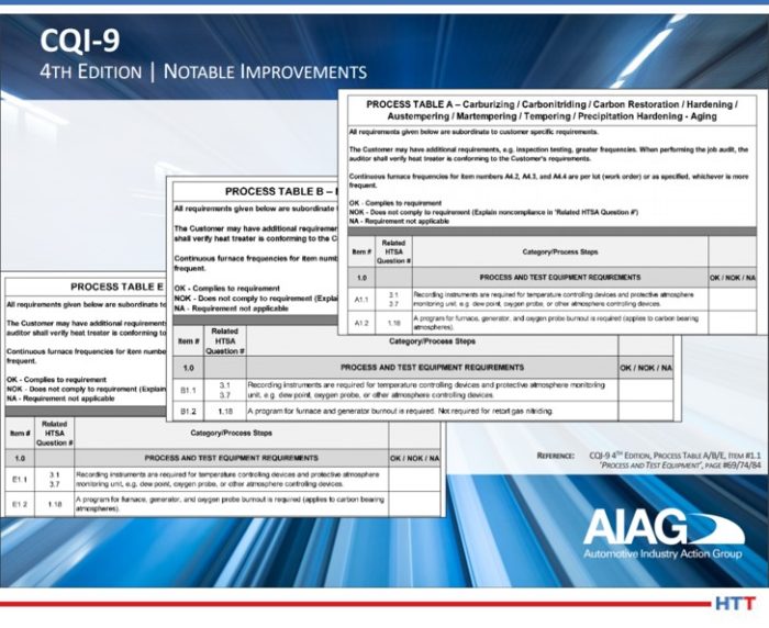
Process Table A covers carburizing, carburnitriding, carburrestoration, austempering, and precipitation hardening or aging.  You’ve got sections like B- this covers nitriding and ferritic nitrocarburizing.  Then you have process table C which covers aluminum.  Process Table D covers induction.  Process Table E covers things like annealing, normalizing the stress relief.  And we go all the way up to process Table I.  So, there is a process table for each unique type of heat treat that is out there in the industry and this allows some very specific topics to be covered in those types of processes.  They all cover pretty much the same thing, so I’ll go back just to run through the headers of Process Table A.

The first portion of it is Process and Test Equipment Requirements.  What are the rules of engagement for those items?  The same thing for pyrometry.  There are specific call outs in the process tables.  If this is part of your system, you have to play by these rules.  Some of them will point you to specific sections of pyrometry.  So, if you’re looking at the thermocouple and calibration of thermocouples, the process table is going to tell you that you shall conform to section P3.1 which covers all of those.

Interview with Justin Rydzewski, James Hawthorne, and Doug Glenn
Source: Heat Treat Radio

It also covers the process monitoring frequency.  How often do you have to check your temperatures?  What are the rules of engagement?  It calls out specifically each portion that may be included in that type of process.  If you have a batch style furnace that covers that process, it has certain rules for you to manage your batch process.  If it’s a continuous furnace, you have certain rules on how you would manage that continuous.  If your process has an endothermic or exothermic generator or even some type of nitrogen methanol system, there are rules of engagement on how to manage or review that system for those items.

Then you get into things like inspection. Your in-process and final test parameters are also covered here.  The last portion of it, in section 5 of the process table, is when you get into things like your quenchant and solution test parameters, and what are the rules for checking that.

What’s really nice about the document is that as you traverse the document, for instance, we have in the quenchant and solution test parameters, it’s A5.1.  The next column over, it tells you what is the related HTSA question.  It is set up in a way where you can go to the HTSA right from the process table and see if you’re compliant to what’s listed there as the shell statement and the requirements or the frequency for checking those.

DG:  That answers another question we were going to address, and that is, how do those process tables work with the HTSA?  It sounds like, in a sense, they are cross-indexed. Is that it?

JH:  That’s correct, Doug.  Like we spoke about in the last interview when we were talking about the job audit, the job audit is set up the same way: It has that same column, it tells you what the related question is, and it affords you the ability to easily traverse the document from the questions in the HTSA to the requirements in the process tables.

DG:  Justin, anything else from you on that?

JR:  The way that I typically frame it for people new to CQI-9 is that the process tables essentially define two things. First, your tolerances for process and test parameters, and second, your frequencies for those process test parameters in testing parts, which are specific to each heat treat process.

As James mentioned, there are nine process tables.  The requirements in each of those process tables are going to be specific to that process.  The requirements within the HTSA are intended to be broad and generic.  They’re intended to be applicable to any organization performing one of those heat treat processes.  As you go an HTSA, you will be notified when to refer to the process table for some specific aspect of the tolerance or frequency portion on that particular requirement.

DG:  It sounds like a lot of work has been put into the cross referencing, making it simple and making it user friendly, right?  So, whether you’re in the process or whether you’re in the HTSA, you can quickly and easily find the portion in the other section of the spec that applies to what you’re doing.

JH:  That’s correct.  Plus, it does afford you the opportunity to find compliance in a simpler fashion.

JR:  And to also specify tolerances and frequencies that are appropriate for that given process.  If I’m heat treating aluminum, I might have a tighter tolerance than that of hardening steel.  They are very two different processes susceptible to different things, so the values need to be different.

DG:  When you’re looking at the changes that were made from Rev 3 to Rev 4 with these process tables, is there anything that jumps out at you?

JR:  I think one of the most notable changes is an item that wasn’t changed, actually, and that was the formatting and grading system retained from the 3rd edition.  The primary focus of our efforts with the process tables this go-around was to enhance that clarity.  The most notable change across many of the process tables was the added requirement to continuously monitor and record that temperature control signature for generators.  So, for atmosphere generators, that temperature side of things needs to not just be monitored, but also recorded.

DG:  Having taken just what we’ve heard today about the process tables, thinking back to what we covered in the last section on the HTSAs, and going back, Justin, even to your first episode that we did on pyrometry, it seems like there is a lot of stuff here.  The CQI-9 comes in at 115 pages long, I’m guessing there are going to be people that start dipping their big toe into this thing and say, “What the heck?  I’m struggling here!  I don’t understand.  What’s required of me?”  From what we’ve talked about, before we hit the record button, there are some other very helpful things in this spec besides these table requirements and things of that sort.

Let’s talk about those a little bit.  What are some of those other resources that will help simplify the execution of this spec?

JR:  There’s a lot to it, but the underlying intent was not to confuse or bombard the organization with unnecessary rules and just allowing people to figure it out on their own.  Everything goes through a “stink test” as we’re writing this up.  Everything must make sense to us.  If it doesn’t, it’s typically not added in or it’s refined and beat up until it is okay and then added in.

What can we do or what are the things that would be helpful to the end-user to make sure that they’re adhering to these things and that they understand to a point where they can adhere to it? It is not uncommon for me to find my customers having no problem following the rules so long as they know what they are so that can understand them and they make sense.

To convey that and get that buy-in, we’ve added a few elements and refined others.  I think the most significant one, and it is in the section within the document that I reference most, is the Glossary of Terms.  There is a lot of really good information in there.  It’s not that I’m referencing the Glossary of Terms because I don’t understand what the word “calibration” means or what the difference is between a “control thermocouple” and a “monitoring thermocouple”, it’s how did we define those terms relative to CQI-9 in terms of CQI-9?  How did we intend that word to be utilized?  Sometimes you can find those little bits of detail that make it easier to understand or to capture what some of the requirements are for that are noted within the rest of the main document.

JH:  There are also some illustrations added to the Glossary as well.  There were a couple there before, but there was some refinement to those illustrations that were in there.  Even those harder to define portions where we put those illustrations to help drive home the intent of the message, I think that was done very well in the Glossary section.

DG:  Would you say, James, that that’s the major change to the Glossary, or are there other things that changed there?

Source: Markus Spiske st pixabay.com

JH:  We went through the entire document from cover to cover.  There are many, many minor changes across the board, but there were some definitions that were added to the Glossary as questions came up during our normal meeting cycles, or that came from end-users when asking them how we should define something.

As those questions came in, we added those definitions to help with that guidance.  Especially, as Justin said, as we’re talking in the meetings, if we’re hammering away at it and we have it digested in the room – we understand what we mean – how do we send this message to the rest of the users out there in the world?  The Glossary ended up being a great place for items like that, as well.

JR:  Right.  So instead of using six paragraphs to describe a certain requirement or whatnot, just use proper terminology and then let’s define adequately those terms, which may be contested or not fully understood immediately, in the Glossary of terms so that there is a clear idea of what it is we’re trying to get across and not have to make this thing 185 pages.

[blocktext align=”right”]“In the context of this document [the CQI-9 revision 4], the following definitions shall apply.”[/blocktext]A real good example of things added into the Glossary would be terms that perhaps we all take for granted, terms that you understand what it means, but when you poll ten different people, their definitions are just slightly different.  For example, “grace periods” was a word we added into the Glossary.  Not that it’s an overly complicated term to understand, but relative to the document, it can have an impact on how it is you interpret those certain requirements and what it is that it means for you.  “RTD” was another one added in there from a sensor standpoint.  I think another that might get some attention is the inclusion of “sintering” and “sinter-hardening.”  There was a fair amount of contention on the sintering side of things that CQI-9 wouldn’t apply.  Then we included sinter-hardening, but we didn’t necessarily define the difference between the two processes.  Now, there’s a distinction made, and it’s included in the Glossary.

DG:  As far as the Glossary goes then, is there any guidance on when it should be used?

JR:  Personally, I would say as often as possible.  It is an incredibly overlooked portion of this document.  It is amazing how much confusion can result just from misunderstanding a word that was used.  Using the example of “grace period”; it’s not that I don’t understand what grace period means, it’s that I want to know what grace period means specific to CQI-9.  How is it intended to be utilized?  My definition might be different.  I want to make sure that I’m lining myself with the definition of the word as it’s defined.

There is a statement at the beginning of the Glossary that says, “In the context of this document, the following definitions shall apply.”  So, it’s within the context of this document.  I may have a different context of that word, but it doesn’t matter what my definition is, it only matters as to how it’s defined within this book, the context of this document.

DG:  That’s a good encouragement to have people refer to that Glossary.  Even if you think you know what the word means, it’s probably not a bad idea to make sure that you understand how it’s being used in this document and don’t impose your own definition.

JH:  There is one other thing I would offer, as well.  I totally agree with what Justin is saying, and I think this speaks volumes or reinforces the things that we’ve talked about already on how one portion of the document supports the other portion of the document and supports the other side.  This document, through and through, supports itself.

[blockquote author=”James Hawthorne, Acument Global Technologies” style=”1″]This document, through and through, supports itself.[/blockquote]

DG:  Let’s jump to instructions.  Probably the most important part of any spec or document is the instructions.  Let’s talk about those for a moment, including maybe references, illustrations, figures, and things of that sort.  Major changes?  What should we know about instructions, references, illustrations and figures?

JR:  There are support elements within the document that we’ve spoken about with the glossary of terms and what not, but there are also instances where instructions are called up… Step-by-step instructions on how to do something so that you can feel confident that you’re doing it correctly.  For doing the HTSA (heat treat system assessment), there are instructions for completing that with the process for going about doing the assessment there, or even as simple as completing the cover sheet for the document or the job audit.  There are instructions provided throughout to try to encourage and support someone’s effort in adhering to the requirements in the document.

DG:  Let’s talk about references, illustrations and figures.

JR:  Within the pyrometry section, specifically, there are a lot of instances of illustrations.  For the system accuracy testing illustrations, the intent is instructional.  It is to allow someone a means of seeing it visually both how it’s to be performed and how to correctly perform it.

Whether it’s a probe method A system accuracy test versus a probe method B system accuracy test, the illustrations included now are a bit more clearly refined.  The focus was on eliminating anything that was unnecessary from that illustration to allow the user to more easily focus on those elements that are critical.  The user will find a lot of improved illustrations throughout the pyrometry section.

You might have no issues performing a system accuracy test and you might have been performing them for some period of time. However, it’s still a pretty good idea to make sure that you’re doing it in the manner that CQI-9 requires in order to see if there is anything in there for added guidance and to make sure that you’re not overlooking something. That just includes simple math to perform one of those tests.  Those are also illustrated to show progression of how to go about doing that test properly.

DG:  Are there other resources within this spec that are available to help the user?

JR:  If there is still confusion, it’s not hopeless.  There are other means by which people can reach out to try to get clarification on different interpretations of requirements.  James and I just recently participated in a roll-out where we had a Q&A for people to bring their questions regarding confusion around certain requirements. We provided answers from a clarity standpoint.  That support doesn’t go away, nor is it just available at special events like the roll-out.  At any time, people can, and often do, email into the AIAG with their questions, looking for guidance on certain matters.

If it’s as simple as- “I don’t understand question 214,” write in and ask the question and see if you can get some additional guidance.  If it’s “I don’t understand pyrometry,” that’s a bit of a broader question and you’re probably not going to like the answer you get back (~chuckle~) and you’re probably not going to get what you’re looking for in the answer you get back, but there are many other sources for support outside of the document.
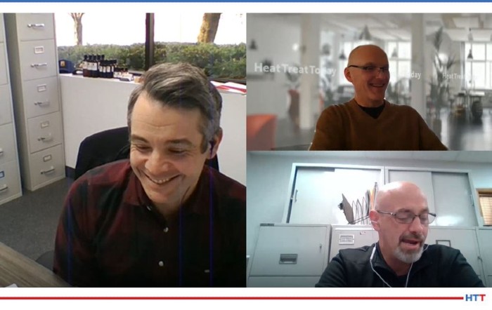
Justin and James recommend reading the whole document and participating in question submission forms to gain a greater understanding and voice in the CQI-9 requirements.

If the document doesn’t have enough, look outside the document.  The AIAG is one of those sources.  Your customer is another one.  If you work with outside service providers (I’m speaking from my world of things – pyrometry), lean on them for guidance and things you don’t understand.  I have my nose in these documents constantly, so my understanding of it is pretty alright.  I can afford some additional guidance or interpretation.

I guess the advice I would have is don’t jump at something blindly and say “it’s going to be enough.”  You’re going to want to have something behind you to give you a little bit more substance than that and to have some confidence in what you’re doing. Otherwise, it will have the tendency to snowball on you.

DG:  Because these documents are “living documents”, they are continually evolving.  Let’s say someone has a suggestion for a change that they would like to see made in a future Rev 5, what should they do?

JH:  At the back of the book, we have what’s called a maintenance request form.  The maintenance request form is a very short and sweet form that allows document users to submit for committee review what changes they believe should be made.  This would give them the forum to always have their voice heard and how they feel, or believe, something should be managed.

To go back to what we were talking about, the CQI-9 technical committee still meets quarterly.  As Justin alluded to, we had questions from the roll-out, but a good portion of our first post completion meeting was answering questions for the heat treater at large to help give that clarification.  And, when we come across a question where we don’t really know what the person is asking or looking for, we give those questions back to our AIAG representative. They may reach out to that submitter to gain clarity on what was being asked so that we can give the best answer possible, not just potentially dilute it by giving an answer just of the sake of answering the question.

There is a lot of opportunity there and as these maintenance request forms come in, they will be handled.  They’ll be handled with the committee and the group will work on it and develop the best answer.  That answer may be, let’s look at making a change, whether that’s through some form of errata or by “putting it on the shelf” until – hopefully a long time from now – we look at a 5th edition. This gives us the ability to capture these things and make sure that it stays on out radar.  We want to make sure that they’re taken care of with the urgency that’s needed.

JR:  I think an item of note here, to make it clear, is any of those maintenance request forms that are sent in, all of them are reviewed by the technical committee.  They are all reviewed.  Anything submitted will make its way in front of that committee to be reviewed to on their agenda.

DG:  What should these forms be?  Is it just for document changes or for other things as well, for suggestions and whatnot?

JR:  It’s for document changes as well as a suggestion box form.

DG:  We’ve covered a lot in this third episode.  We’re going to have a fourth episode that is going to deal with some practical tips from you guys on the actual execution of these things, but is there anything else that you would want to tell the listeners regarding the spec itself?  Any other concluding comments?

JR:  From a process table standpoint, this was something that was reiterated throughout the entire roll-out presentation: it really does take reading the entire document to capture all of the changes.

Some of them are quite minor and some of them stand out as being significant, but for the most part, they are minor, and sometimes minor ones can be very easy to overlook.  There used to be requirements for calibrating your hardness testers on an annual basis.  Those requirements have now been expanded to all lab and test equipment that require an annual calibration.

Another element that was included in the 4th edition was we made an effort to increase the clarity and guidance for the use of exceptions that are applicable to section 4 requirements of the process tables.  For example, these would be used if you’re employing a surrogate test piece in lieu of sectioning some large or expensive product.  If anyone is interested, the clarity is included on page 9.

But make note, these are not blanket requirements; these exceptions require customer approval and ultimately OEM approval, so they must be documented and approved by a customer and increased in your PPAP (Production Part Approval Process) control plan.  There is a fair amount of added clarity on that topic, so it’s something people might want to take a look at and dive into just to make sure that they’re familiar with it.

DG:  James, any concluding comments from your side?

JH:  I think I’d just reinforce a little bit of what Justin was mentioning earlier.  Read the document.  Read as much of it as you can and try to understand as much as you possibly can.  We made a lot of changes.  Some of them are very minor, but some of those minor things could potentially be overlooked if you don’t step back and take a moment to understand the document and how each system, or each portion of the document, works with each other.

DG:  The next episode is going to have some practical tips.  We’re going to pick the brains of these two gentlemen on navigating Revision 4.  You won’t want to miss it.  There are going to be opportunities here to basically figure out some of the details.

If you have questions, feel free to send them in.  You can email htt@heattreattoday.com if you have any questions and we may get those answered.


Doug Glenn, Publisher, Heat Treat Today

Doug Glenn, Heat Treat Today publisher and Heat Treat Radio host.


To find other Heat Treat Radio episodes, go to www.heattreattoday.com/radio.

Heat Treat Radio #47: Justin Rydzewski and James Hawthorne on CQI-9 Rev.4 (Part 3 of 4) – Process Tables & New Resources Read More »

Heat Treat Radio #46: Heat Treat Parts Washing with Thomas Wingens

Heat Treat Radio host, Doug Glenn, interviews Thomas Wingens about recent developments in parts washing technology. While many heat treaters gawk at the cost, it could be even more costly if avoided. Throughout the episode, check out the pre- and post-washing articles listed within the transcript. Click the image for the resource.

Below, you can either listen to the podcast by clicking on the audio play button, or you can read an edited version of the transcript.


Click the play button below to listen.


The following transcript has been edited for your reading enjoyment.

Doug Glenn (DG):  We’re here today with Thomas Wingens, who is no stranger to Heat Treat Today.  Thomas is the owner, founder and president of WINGENS LLC – International Industry Consultancy.  You can learn more about Thomas’s business at www.wingens.com.

The last time we spoke with you was in a radio episode in October of 2016.  We were talking about some “top-of-the-mountain” type of things.  The episode was called Megatrends with Thomas Wingens,” and we were talking about some very, very broad categories of megatrends going on in the heat treat industry, which, by the way, has been one of the top listened-to episodes that we’ve had.  Even though it was 2016, much of what was said in that episode is still very much worth listening to, so I recommend it to people to go back and listen to.

But Thomas, you and I need to get down off the 30,000 elevation mountain and we need to talk about a very specific topic today, and that is parts cleaning or parts washing.  You just recently completed participation in a webinar about parts cleaning for a company called Hubbard-Hall, Inc.  I want to touch on that for a little bit, and then I’ve got several different questions for you about parts cleaning.

First off, tell us about that webinar – how did it go, was it well attended, and what was your impression of it?

Thomas Wingens (TW):  It was well-attended thanks to you, Doug.  You did a wonderful job promoting it on your website, Heat Treat Today, and we had a broad spectrum of listeners and very specific questions after the webinar.  They were broad because it was an international audience, mostly from North America but also from Europe, but also broad in the sense of different applications.  Washing/cleaning is, indeed, a broad spectrum because everything that is contaminated is to be cleaned for various purposes.  Here, in our discussion today, it is a niche just for the heat treat industry.  That’s what we want to talk about today.

DG:  That’s exactly right.  Parts cleaning can come either before heat treat, after heat treat, both, or it can be all over.  Before we jump into specifics about some of the new technology, it might help some of our listeners if you could give us an ever-so-brief overview of the past: what have we dealt with and what has been the state of washing and cleaning in the heat treat industry?

TW:  As much as heat treating is a necessity, washing and cleaning in heat treat or for heat treat is even more of a necessity you’d like to avoid if possible, because it costs money and people do not necessarily see the added value.  As a heat treater, you’re selling the hardness of the material as a value added, not necessarily that parts are clean – that’s not your main focus.  But it is a necessity which, over the years, has received more and more attention for various reasons.

[blockquote author=”Thomas Wingens” style=”1″]technologically, you need to clean it to avoid the flaking of the stop-off paints of carburizing, for instance.  But with the rise of the nitriding and ferritic nitrocarburizing… it is so important to clean it. [/blockquote]

So, why do you clean parts?  Well, obviously, the cleanliness or the appearance of a part reflects the quality of a part.  But also, technologically, you need to clean it to avoid the flaking of the stop-off paints of carburizing, for instance.  But with the rise of the nitriding and ferritic nitrocarburizing in the industry, and the higher demands on the predictable nitriding layers, it is so important to clean it.  It is so difficult because it is a low temperature process.  People don’t necessarily see it unless they look at the microsample and see spotty nitriding layers.  They are hard to come by and so that can be a bit too clean.  But also commonly, of course, in other industries like brazing, you have problems with whitening of the parts of the filametal getting the parts on that clean.  Or, within the powder metal industry, it is very difficult to clean.  It really depends on what process you’re looking at within heat treat which will determine the cleaning of the parts.

Historically, to answer your question, it was a very simple thing.  Let’s look at atmosphere heat treating.  You have the parts come in after machining and you have some lubricants, cutting fluids, deep drawing material fluids that need to be removed before heat treating.  In atmosphere heat treating, that’s a fairly easy task, because if you have some residue, usually it burns off.  But after oil quenching, obviously you have quench oil on the part.  If you don’t clean it well, your temper furnace, the tempering process, you will have a lot of smoke. So, you need to wash before tempering.  You usually have a water base, alkaline washing machine with a simple belt skimmer and that’s how it was done, and is still done, for many years.

Influence of process variables on proper cleaning of parts prior to heat treatment.
Source: “How Parts Cleaning Maximizes Heat Treatment”
gearsolutions.com

Back in the day, it was much simpler, like 25-30 years ago, in our heat treat shop.  It started when the material you had on the surface of these parts became more difficult; environmentally-friendly cutting fluids were very hard to remove, for example.  Back in the day, people were happy when parts were not black and had no scale.  But atmosphere furnaces got tighter, there were better controls, and customer’s expectations were higher. So, they want to have clean parts, right?   The way to get it is to make sure that you fully removed all the oils, especially after quenching.  So, I went to the old quenchmen, usually that’s what you do, because they understand their oil and how to remove that oil.

That helped a lot to adjust the alkaline water-based washer.  Removing the oil of the water solvent was difficult sometimes.  Different skimmer technologies certainly helped, but it came to a limit.  Especially now, it’s getting a little more difficult when you have parts that are dense, like stamped parts which stick to each other.  It depends on how dense you load it, so the geometry of the part is very crucial.  If you have scooping parts which carry on the oil or if you have single-ended holes, then it becomes a little bit more tricky.  To remove these oils, either before heat treating or after quenching, is much more sophisticated and more challenging.  Back then, we were looking into a different washing machine, but then you really open up a can of worms.

You are confronted with a lot of questions from the washing machine manufacturer and so you really have to learn how to clean and what’s out there in the market.  Then you get the sticker shock – how expensive everything can be – and that’s when the homework really starts.

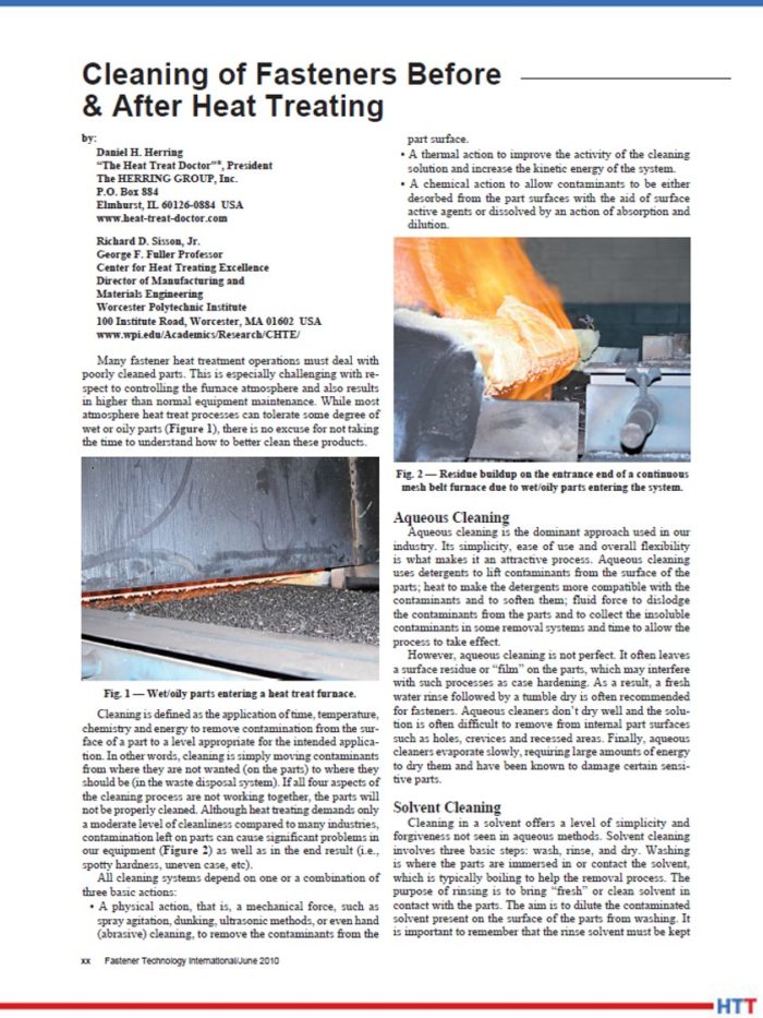
Click the image to read the article by Dan Herring, The Heat Treat Doctor, and Richard Sisson, Professor
Center for Heat Treating Excellence

DG:  Let’s talk a little bit about that.  Let’s put ourselves in the shoes of a manufacturer who has his own in-house heat treat line and let’s say he either has a washing system now or is looking to get one.  He definitely has some pain points.  He has some things he’s thinking about, things that are potentially keeping him up at night.  What might be some of those things?  You’ve probably already hit on some of them, but in a nutshell, what are these guys worried about and what do we need to be thinking about when we’re thinking about purchasing and/or using a parts cleaner/parts washer?

TW:  The benefit of in-house heat treating is that they usually know what they put on the surface of the material.  A commercial heat treater is a different story – it is much more complex because you’ve got these various different contaminations.  For in-house, they usually know their cutting fluids, the corrosion protection, the forming lubricants.  So, I think that’s how you start.  You need to know what you put on the surface first and then you’re in a better position to know how to remove it.  If you know what you put on, then how to remove it is a matter of having the right cleaner system.  The right cleaner system needs to be run in the right equipment and the application time and the temperature all together give you desirable results.  Most people don’t do it that way, to tell you the truth.  They have a system that they either live with and accept, and then later on, sometimes, focus on the technical results.  It is very hard to see the effect because it is not so defined, not so obvious sometimes.

To answer your question, it is not necessarily a “pain point” which is present, it is something which comes up at a later time when you get claims.  When you see, for example, there is some nitriding layer which is not as expected.  Why do we have this spotty surface?  Why do we have problems with our equipment?  Why do we have spotty carburizing layers and all that?  It’s not always detectable that it is a washing issue.  This usually comes in the later stages when parts are used and when parts are in the final assembly or even out there for many years.  It usually comes up at a much later point and that makes it so risky.  That’s why people should pay more attention to this because it can solve problems that they are not necessarily aware of at this point.

DG:  For the past 20 years, the technology for parts cleaning/parts washing has advanced.  Again, we don’t talk a lot about it here on Heat Treat Radio, but it is an integral part of the heat treat process, so I want to spend more time on it.  What might be some of the more notable, recent advances in parts cleaning/parts washing technology?

TW:  It is many-fold.  Let’s look at nitriding, atmosphere heat treating, and vacuum heat treating, which are the most common processes.  Every process has different points to address.  In atmosphere heat treating, you want to make sure you have clean parts before you temper.  For the most part, it is simpler.  If you have high expectations, you maybe want to look into a solvent cleaner, but for the most part, you might be happy with an aqueous alkaline cleaning system.  It really depends on the parts you have and the desired outcome.

Click the image to access the article.

For vacuum heat treaters, the vacuum is a cleaning machine by itself, so you protect your investment by the vacuum pump and your vacuum levels if you clean them up-front.

But the nitriding is a very hot topic these days.  I have personally tried a lot of different washing media.  It was easy in the past because we all used trichloroethylene perchloroethylene open bath.  That’s not environmental or health-friendly and that cost a lot of trouble, back in the day.  You could clean anything; it was easy, simple and cheap.  I did it myself. I worked a lot on this open trichloroethylene, but that is not what you want to do to protect your people and your health.

A good solution today to really address the various contaminations and the broad spectrum is to use modified alcohols.  They are environmentally friendly, on the one hand, and they can cover nonpolar, meaning oil and grease contaminations, and also polar water soluble emulsions. So, they have a very wide spectrum of cleaning organic and inorganic contaminations.  If you have just a perchloroethylene cleaner, you may end up with residues that are emulsions with stains and you wonder, Why is that perchloroethylene moving? It’s because it is a polar contamination and it is better with a water-based cleaning system.  The modified alcohols cover both sides.  So, you will not get stains but you will get, most commonly, cooling fluids and corrosion protections taken away at the same time.

DG:  And these modified alcohols are relatively environmentally- and people-friendly?

TW:  They are.  And, most of all, if you operate them in a closed system, then they really shine because you don’t carry out so much; you keep it all in close and safe, so much that some companies operate the modified alcohol, believe it or not, in an atmosphere integral quench line very close next to an atmosphere open flame furnace.  But because they are vacuum tight, the whole system is vacuum tight, and they have no residue, it’s a very nice system and that is also safe.  Also, modern systems can tilt.  Not only can they flush, rinse and dry, they can also tilt a little bit.  So, if you have scooping parts or if you have single-ended holes, then you get all the residual solvent out.

DG:  There is material handling inside of the washer or the cleaning system that actually will oscillate the basket, perhaps rotate it a bit, so that it’s dumping out any extra liquids or anything of that sort.

TW: Exactly.

DG: Any other advances in technologies that we should know about?

Click the image to access the article.

TW:  It really depends what materials and what geometry in size parts you have.  Some are very hard to clean.  On the corrosion protection deep drawing materials, you have special deep drawn parts that have phosphor and sulfur additives and they work themselves into the surface.  They are very hard to be removed and if you don’t remove them, you will receive spotty nitriding layers and the recovery of the media.  I think that’s an important part to mention.  That has changed quite a bit.  Most of the washing machines usually clean well on day one.  Over time, they fade.  The cleaning results will change.  In a lot of systems, especially phosphates and sulfurs, they accumulate.  It’s a chemical plant and they have new reactions.  So, the treatment and recovery of these solvents is a very important part.  I think that has changed quite a bit over the last years.  Now they have sensor technology, but they fully control this in a fully enclosed system, which is environmentally safe, and it fully controls the status of the cleaning agent, whatever that is.  They know exactly what to do to reclaim it or to readjust it, and that technology, I think, over the last ten years, has got much better and so you now have a consistent and clean outcome of the part surface.

DG:  Let’s move to a question that I think will be helpful to listeners, especially if they’re considering purchasing new equipment or upgrading current equipment.  I know a lot of people appreciate “What do I need to be asking?”  If I’m getting ready to purchase a new piece of equipment, what are the questions that I should be asking either of my team in the shop, on the heat treat line or whatever, or to the manufacturers of these washing/cleaning pieces of equipment.  What are some of the questions?

TW:  The simple question is: What is the material you have and what is the size?  This may be something you don’t want to cover 100% of your parts.  If you have that 8′ gear and a five ton dye just once a year, you don’t necessarily size your cleaning machine for that part, right?  You take a piece of cloth and a spray bottle and you do it that way (~chuckle~).  But you should look at 80% of the parts you have.  You want to put that in-line because once the corrosion protection is off, you should treat it.

Wet and Oily Parts Entering Heat Treat Furnace
Source: Herring and Sisson article above

Of course, you need to know what you want to remove.  In in-house heat treating, that’s easier because you have the list of materials and cutting fluids you have.  Then, what is your expectation of the outcome?  That is difficult.  It is difficult because there is not a real measure, like in hardness.  To determine the surface cleanliness, that is really hard to have that consistently over time.  Then of course, the pain point of cost.  My big advice is that people should really not cut corners and start on the low end and work their way up.  That is a typical scheme that is happening so often that people say let’s try the cheaper version and then they find out after years it did not work and they have to upgrade.  They have claims but then they have to invest again.  It pays off to experience the pain once.

DG:  That is so typical and it’s good advice, not just for washing equipment.  So many people want to start on the cheap end and then they have a bad experience with the equipment and they say all these washers are cheap junk.  Well, that’s not necessarily the case.  Sometimes, like you said, you need to invest.  If you’re going to get hit, get hit once and let’s get it over with and move on and enjoy life.

Click the image to access the article.

TW:  Exactly.  And then, there is the overall running total cost of ownership, of course, how much you use of the solvents and all that, so it’s the whole system you have to look into.  I would always recommend, that it’s better to go a step above than to go a step below because it’s not so obvious that you’re having failures due to bad cleaning.

DG:  I’m assuming that if one of our listeners wanted to get that list of questions to ask, they could contact you and you’d help them with that.

TW:  Yes, sure!

DG:  Let’s say someone wants to get a little more educated on parts cleaning, parts washing and that type of thing.  Do you have any resources that you would recommend that people look into to help start educating themselves?

TW:  There are companies, equipment manufacturers, consultants, like Hubbard Hall, that have a broad portfolio.  There are independent consultants who can look at the big picture because it sure makes a difference on what you want to accomplish and what treatment you have to size the system right for your purpose.

DG:  That probably captures it, but I think I was looking specifically for if you wanted to learn more generally about parts cleaning.  Are there any articles out there, websites?  But I think these equipment manufacturers are probably a good place to start on that, as well.

TW:  It is not as straightforward as you would like for a furnace.  It’s really niche, so you have to dig a little deeper.  But, once again, we are happy here to help.

DG:  Yes, good.  A lot of your furnace manufacturers are going to at least know of parts washing suppliers and things of that sort, so they could also help you.  If you’ve got a good relationship with your furnace manufacturer, they could probably help as well.

I will mention this too, because I think it could be helpful, you can obviously Google industrial parts washing, industrial parts cleaning, you can find out who it is that sells those.  Some of you listeners might know of what used to be called Thomas Register and now is called Thomasnet.com.  I highly recommend those people; they’ve really evolved with the times and I think they’ve got a good resource of people who could be suppliers.  Also, within our very industry, is Industrial Heating, who is actually a competitor of ours.  But I’ve got to give them credit, they’ve got a good buyer’s guide that has a parts washing section in it.  I would recommend, if you would like, to go there.  It is www.industrialheating.com and look for their Buyer’s Guide; it actually has a list.  If you’re listening to this podcast after June of 2021, then go Heat Treat Today’s Buyer’s Guide because we will have one then and we will also have parts washing in there.  Those are some other good resources to access, if you’re interested.

I don’t know if you remember, back in the day, Abar Ipsen.  I used to know the president Tom Farrell.  They were into vapor degreasers.  Tell me about those, if you know, what they were and how they work.

TW:  It was a vacuum cleaner and it was called ECOCLEAN.  It was an ecologically sound cleaning system.  The ECOCLEAN vacuum degreaser worked in this way- you heated it up to the vapor point of your oil, it evaporated, the oil evaporation got cooled down and was then captured, it was condensed in a trap.  That worked really good if you only have one oil with a defined vapor point.  This special technique does not work in a commercial heat treat shop necessarily, but it worked really well and was used in the powder metal industry.  You have sintered parts that soak up the quench oil or the foaming media.  You could really use it to vaporize at a very defined temperature to that specific oil.

Another side effect that was really nice, was you had preheated parts.  It was done before you went into the sintering process, so you had decreasing of the press media which was on the surface of the green parts and you vaporized that oil and then you took that heat and put it right into the sinter furnace.  That worked well in that specific application.  Other than that, it’s not a broad spectrum cleaner and it does not address the various contaminations you have on the surface.

DG:  Are they still used, do you know?

TW:  Abar doesn’t sell them anymore.

DG:  But vapor degreasers, in general, are not necessarily a type of cleaner that is used?

TW:  I think it comes down to the cost of the system and the value it brings you, so that is not necessarily what is used today.

DG:  There have been a lot of advancements in technologies and sensors in the heat treat industry.  Do you know if any parts washing companies are using in situ, real-time, live, loopback types of sensors to clean parts?  In other words, can they measure the cleanness of a part and continue washing until it’s done?

TW:  They do measure the cleaning agent, yes.  The cleaning detergent is measured in situ and controlled and you can see the status at any give time when you need to take action and recover the system or to renew the potency.

DG:  But as far as actually measuring the cleanness of the part, nothing that we know of at this point is used to actually measure the cleanness of the part?  I’m not even sure that’s possible, but I was just wondering if it was.

TW:  No.  It would require a scanning of the surface and I haven’t seen that.

DG:  Have you heard of or seen any single piece flow washing systems that are actually in-line with a machining, heat treating, washing, tempering line?

TW:  A single part, I have not heard of.  There are contiguous washing machines that usually are water-based which work well, for the most part, but when you have solvent washers, like modified alcohols or hydrocarbons, then these are closed systems in the vacuum batch style.  If you would do this in a single batch, you would just make a very small batch, but I don’t know that you’d want to integrate this into a system.  Usually, single parts are much easier to clean than a batch.  Picture a lot of washers in a basket that stick together… That’s a much bigger challenge than a single piece.

DG:  Let me recommend to the listeners that we do a couple of things.  One, I mentioned back in October of 2016 we had another interview with Thomas Wingens of Wingens International Consultancy, where we were talking about heat treat megatrends.  I recommend that you go to our website www.heattreattoday.com and search for Wingens and you should be able to see that episode of Heat Treat Radio there.  Feel free to listen to that as I think it will be very helpful.

One other parts-cleaning/oil-cleaning type episode that we have done on Heat Treat Radio was with a company called SXOil Lifter.  This is a little different as it is removal of oil from quench tanks and things of that sort, but it’s along the line of cleaning, at least keeping your quench tank clean.  That was done in July of 2018.  Again, if you go and search for SCOil Lifters, you should see that episode as well.

Thomas, thank you very much.  I think it’s been very informative.  We will, include your contact information as we wrap up, but we appreciate your time and expertise.

TW:  Thank you very much, Doug.  It was a pleasure to be, once again, on the show.  I think we need to upgrade the outlook of this trend of four years, as COVID has changed things for sure.

DG:  Well, once every four years is probably all you can take of me, Thomas. (~chuckles~)


 To contact Thomas Wingens, email thomas@wingens.com, or head over to www.wingens.com. His phone number in the U.S. is 724-732-3338.


Doug Glenn, Publisher, Heat Treat Today

Doug Glenn, Heat Treat Today publisher and Heat Treat Radio host.


To find other Heat Treat Radio episodes, go to www.heattreattoday.com/radio and look in the list of Heat Treat Radio episodes listed.

Heat Treat Radio #46: Heat Treat Parts Washing with Thomas Wingens Read More »

Heat Treat Radio #45: Justin Rydzewski on CQI-9 Rev.4 (Part 2 of 4) – HTSAs & Job Audits

Heat Treat Radio host, Doug Glenn, conducts Part 2 of this 4-part series with James Hawthorne of Acument Global Technologies and Justin Rydzewski of Controls Service, Inc. about Revision 4 of CQI-9. This time, the conversation focuses around heat treat system assessments and job audits.

You are about to listen to the 2nd episode in a 4-part series on CQI-9 Rev. 4.  You can find the previous episodes at www.heattreattoday.com/radio.

Below, you can either listen to the podcast by clicking on the audio play button, or you can read an edited version of the transcript.


The following transcript has been edited for your reading enjoyment.

Doug Glenn (DG):  Welcome to Heat Treat Radio.  I am here today with Justin Rydzewski from Controls Service, and a new guest we’re going to introduce to you in just a moment, Mr. James Hawthorne from Acument Global Technologies.  We are going to be talking about CQI-9.  This is our second in a four podcast series on the new Revision 4 of CQI-9.  We want to welcome our guests today.  As I mentioned, Justin is from Controls Service, in Livonia, where he is the director of sales and marketing.  Justin was actively involved on the committee that wrote Rev 4.

Justin Rydzewski (JR):  That’s correct.  I was an active participant in coauthoring the fourth edition.  My most significant contributions were to the pyrometry section.

DG:  Correct.  And pyrometry was what we talked about last time.  So, welcome back.  We are also welcoming James Hawthorne.    I want you to tell folks about yourself, but as I mentioned, you’re with Acument Global Technologies, a Fontana Groupo company, which I believe is an Italian based company, that is located in Michigan, with its  headquarters located in Sterling Heights.  My understanding is you are the heat treat specialist at that company.  If you don’t mind, please tell us a little bit about  the company and yourself as well as your involvement on the CQI-9 committee.

James Hawthorne (JH):  I work for Acument Global Technologies.  I am the heat treat specialist for our North American facilities.  I handle the heat treat systems, the system’s compliance, and quality assurance for the heat treats within our organization.  Acument has been around many, many years.  We make fasteners – nuts, bolts, rivets, washers – for the auto industry.  We make it for off-highway equipment, things like tractors and bulldozers and whatnot, and we also do building and construction fasteners, as well as things that are holding bridges together, and roller coasters — you name it, we probably have a fastener in it.

[blockquote author=”James Hawthorne, Acument Global Technologies” style=”1″]We’ve been working on this document for quite some time.  Through a lot of expertise and many, many, many work hours, I believe we’ve put together a really good product for the industry.[/blockquote]

DG:  We appreciate that!  We were talking before we hit the record button how the world would be a worse place if fasteners weren’t holding stuff together.  I do want to mention, before you go on, that according to the Acument website, the company is described as the world’s most innovative manufacturer of value-added screws, bolts, nuts and cold formed components.

Please continue.  Tell us about you and your role on CQI-9.

JH:  I’ve been in the heat treating industry for over 25 years.  My formal education includes metallography and statistical process control.  I’ve held positions in heat treat including maintenance, working in the laboratory, working in supervision, and now I work in the corporate capacity, which is what led me into AIAG.  We are a member company, and I was brought in to add as much value and knowledge as I could, based on my experiences.  Currently, I am the chairman of the technical committee.  We’ve been working on this document for quite some time.  Through a lot of expertise and many, many, many work hours, I believe we’ve put together a really good product for the industry.

DG:  Basically, you’re the technical director of the committee?

James Hawthorne
Corporate Heat Treat Specialist,
Acument Global Technologies

JH:  The committee chairman.  The important part is to try to keep everybody on task; you’re more of a task manager at that point.  You get a lot of smart people in a room, and trying to corral that intelligence is not difficult; it’s just making sure that we stay in the right lane, get to the bottom of what we’re trying to get to, and complete the specific task in the moment.

DG:  I asked Justin this the last time, and I’d like to ask you, too, just to get your perspective.  How would you explain CQI-9 to someone who has essentially zero understanding of what it is?

JH:  First I’d start with the acronym itself.  CQI-9 is Continuous Quality Improvement.  The purpose behind it is to put together a system that will help you manage and control your process, and at the end of it, the product that you’re delivering to the end user.  The intent is to give you those guidelines to help avoid potential spills or escapes or whatever else may come with that.

DG:  Right, any of the hurdles in the process itself.  It’s mostly heat treat related, yes?  Or is there more than just heat treat there?

JH:  It is the entire system of heat treat.  If you look at the heat treat system assessment, the first portion of it is quality based.  The second portion (section 2) is the floor responsibilities, things that are on task that are being completed.  And third, you get into the maintenance and the pyrometry portion of it, very specific to the pyrometry and very specific to atmosphere control.  At the end of it, there are some very specific induction questions, because when it comes to induction, there is no real furnace at that point, so you want to focus on those key elements of induction.

DG:  Justin, the last time we talked about this, we tried to break this down to keep it simple – the CQI-9 and the four basic sections.  Very briefly, let’s review those and then we’re going to jump into talking about heat treat system assessments and job audits.  Can you give us the four categories?

JR:   CQI-9 is broken down into a few sections and one of the reasons for that, per our conversation last time, it is not exactly like an AMS2750, which is a pyrometry standard.  Instead, this is a system assessment.  It is meant to assess an entire system of heat treat.  It includes a multitude of sections that address the system as a whole.  It starts with your heat treat system assessment, which often utilizes an acronym of HTSA, then you have a pyrometry section, then a job audit, and then your process tables and various different support elements, like a glossary of terms, instructions sheets, and whatnot.  But the four are the HTSA, pyrometry, job audit and process tables.

Read/listen to the first episode. Click the image above.

DG:  As we mentioned last time, Justin, you and I talked down through the pyrometry section which covered things like sensors, thermocouples, calibration, SATs and TUSs.  If you, our audience, are interested in that information, you’d want to go back to the first episode.

James, we’d like to pick your brain a bit on this.  Let’s jump into some questions on the HTSAs, as we’ll refer to them, heat treat system assessments, and job audits.  Let me ask you this to start off.  Let’s go right to the basics: What is an HTSA and what is its purpose?

JH:  HTSA, heat treat system assessment, is a tool that has been developed to help you evaluate how you manage your heat treat system for effectiveness – effectiveness in quality management, effectiveness in the floor responsibilities.  Like I mentioned earlier, understanding that through aspects of training and training effectiveness and into the final section of atmospheric control and atmosphere management and reaction to those.  The purpose here is to have one system, one document that is the rules of engagement for doing heat treat in the automotive world.  What this does is, it allows the automotive industry to give you one spec, one thing to follow.  As opposed to having, say Ford, to give you ten questions where none of them are exactly the same as FCA or nine of them are the same as Ford motor company, where one of them have a specific question.  This encompasses all of those wants and needs from the auto industry to protect themselves, to protect the end user out there in the field that may be using that heat treated component.

DG:  How frequently does a heat treater need to conduct an HTSA?

JH:  The rules of engagement are annually.  On an annual basis you should be evaluating your system for compliance.  The beautiful thing about the HTSA is that it is a living document.  If you find any shortcomings in there, you have the ability to go back and update that and make it match what your reality is after you find the solution to the problem that may have come up while doing your assessment.

DG:  For clarification, these HTSAs, are they conducted by the company, or do they need to have a third party come in and conduct the HTSA annually?

JH:  That’s a great question.  There are no rules to having an independent body come in to do this assessment.  If you have the people that meet the criteria within your organization to do the HTSA, the system assessment along with the process table review and the job audit, you can do it within your own organization.  You just have to meet the criteria that is listed in the book, and these kinds of things are having experience in heat treat, which is the number one thing you must have to be the lead auditor of a heat treat, the understanding of quality core tools and having that audit experience.  Those are the things that you have to do to be able to successfully do an audit and it meet the intent of CQI9.

JR: I believe the intended purpose of the HTSA was initially for it to be supported internally by the organization.  That was the intent of it.  We commonly refer to the HTSA as a self assessment.

DG:  That makes sense.  I assume that when the auditor comes in, he may audit how you did your HTSA, to make sure that it was done well, and all that good stuff.

So the outcome of HTSA is going to be pass, fail, miserably fail; what are the possible outcomes?  I know we’ve talked about “Not Satisfactory” and “Needs Immediate Action.”  I want to deal with those differences, but what are the outcomes?

JH:  “Not Satisfactory” is where you don’t meet the intent of the shall within the related HTSA question.  Now, that could be a simple oversight where it’s very easily correctable- you put the proper things in place and you move on.  If you have something that could jeopardize final product quality, now you’re looking at something that may be a “Needs Immediate Action” and that “Needs Immediate Action” will be evaluated by the assessor and the heat treat organization as to what needs to be done.  CQI-9 does afford the heat treater with 90 days to correct any finding.  If it’s a “Needs Immediate Action,” there should be action to correct that finding immediately up to 90 days.  It’s also important to note that if it’s something that is going to jeopardize product quality, then there is a chance that it “Needs Immediate Action” will be extreme enough to where you have to stop processing – stop processing, fix the problem and then begin processing again.  But that goes to the evaluator.  You have to be able to evaluate that; and that’s one of the many reasons why we look at the assessor, or at least the lead assessor, being a heat treater, because he’s going to understand it, he’s going to know it.  For a commercial house, it’s very easy to have those people available.  In a captive house, maybe not so much, where you’ve got a lot of other things going on plus heat treat.

JR:  I don’t know if you recall or not, James, from the roll-out we had a question that came through, and I don’t know if we were actually able to address it, but they posed a question of why the heat treater was given a greater amount of focus than was in the previous edition.  Somehow, that was an element that required explaining because there was a question of a possibility for there to be issue with doing so.

JH:  If we go back to the conversations that we had about this, I think this was one of the topics we talked at length about, and the rationale behind the lead assessor.  Is it more important for that person to be a good auditor, or is it more important for that person to be a heat treater?  We’re not diminishing the need to have audit experience, at all.  The only difference is that we’re saying that the person that is going to be the lead auditor be a heat treater, because that heat treat experience is going to be much greater than somebody who has audit experience.  Where if an auditor goes out and he looks at every day is cold forming, for example, and how they make the fastener itself, well, when he gets to the heat treat portion of it, is he going to know what atmosphere control is?  Is he going to know what endothermic gas is?  This is the rationale behind this change – that these people are going to understand the language, and that’s the importance.

JR:  The key element is that it doesn’t mean that you don’t have to have the audit experience on that team.  That person is still needed, it’s just the focus shifts a bit.  It doesn’t mean that it is now absent.

DG:  Let’s move on to job audit, James.  It’s different than an HTSA, but what is a job audit and what is the purpose?

JH:  The job audit is the supplemental portion of the assessment process.  The job audit is where you would take apart and walk it through the system and then verify all of the evidence that you’ve put into the HTSA.  You walk the process; you go look at each point specific item based on the job audit flow, and you check: Did the operator check the right amount of pieces?  Does that match what you said in the HTSA?  Did they document their efforts on, let’s say, production report A and process report B, and is that what is represented in the HTSA?

The first part is the “truss,” then you’re verified.  Now, you’re doing some verifying in the HTSA, don’t get me wrong, but this is actually walking that part through the system and ensuring that every box was checked, every “T” crossed and every “I” dotted.

DG:  It sounds like the HTSA is more like the blueprint and the job audit is running a part through and making sure that we match up to the standard, so to speak.

JH:  Yes, sir.  And it’s verification of your reality.

DG:  Is there a requirement as far as frequency of job audits?  How often do you have to do those?

JH:  This is also annual.  You are required to do an automotive part.  I know that some customers might like to see their part in the job audit, but we don’t require it per customer.  If it’s an automotive part, I would say 95 – 99% in the industry, what you’re doing for one customer, you’re doing for every customer, in a 101 kind of standpoint.  There may be some special tests here or there, but overall, your system and your system’s management is going to be the same for one customer that it is for all customers.  If it’s right for one, you’ll do it for all.  And that’s the intent.  Do it with the one automotive customer, and then the next year, do a different part.

DG:  Do you find, in your practical experience, that people are doing more than one job audit a year?  It seems to me, it would make sense to do more than one, but I don’t know.

JH:  I guess it depends on the organization.  I know, for our organization, we do a job audit annually for each process employed.  I’ll give you an example of this.  We have a facility that has belt furnaces and it is neutral hardening.  So, we’ll do a job audit for the neutral hardening.  Then, we have induction in that facility, as well, so we’ll do one for induction.  And then there is stress relief post induction, and we’ll do one for that as well.  For us, in our organization, that’s how we manage it to accommodate the processes employed at our facility.

James Hawthorne and Justin Rydzewski speak about how the heat treat system assessment (HTSA) in CQI-9 has changed.

DG:  Let’s talk about the CQI-9 Rev 4.  What were the major changes to the HTSA requirements?

JH:  Right off the top, the big change was the format.  In the 3rd edition, you had one question that required one answer.  There were many shall statements inside that one question, so you were trying to answer a multifaceted question in one area.  Now, the HTSA is slightly different where you have one kind of overall question and then each shall statement is individually broken out and now you have to show effective evidence inside each one of those shall statements.  Talking through this, maybe it sounds a little odd, but I will tell you that it has cleaned up this document tremendously, where it makes it so much easier to walk the system and expose either your compliance or noncompliance to a shall statement.

DG:  I do have a question here.  You’ve mentioned it several times, but I just want to make sure our listeners understand this.  I assume you’re saying “shall” statements, as in “thou shalt do this and thou shalt do that,” correct?

JH:  That is absolutely correct.  From an auditor’s standpoint, there is a difference between shall and should.  Should is suggested, shall you will do.

DG:  Right.  Shall is a requirement, should is a strong suggestion, let’s say.

Any other changes in Rev 4 as far as the HTSA?

JH:  I would say that there are subtle changes to all of the HTSA questions.  Some of them are maybe not as significant as others, where it’s cleaning up the language or removing some wording just to make the question read clearer.  That clarity to the end user was one of the high priority items for our group when we were doing the writing of this document.

The big thing I would say for anybody using this document, whether or not they’re a seasoned veteran with 20 years of heat treating experience, anything short of reading this document and you’re not doing yourself any favors.  It’s important to walk the document.  It’s important to traverse the document, whether you do it in phases – grab the HTSA and read through it, and then maybe a week later go through another portion of it, especially if you’re getting to the point where your assessment is coming up to be due.  It provides a lot of information and a lot of guidance, and it will help you avoid any potential pitfalls.

[blocktext align=”right”]”DG:  So does that mean less time, hopefully?”         “JH:  100% yes.”[/blocktext]JR:  I would also agree in terms of the changes.  The most significant one is the formatting, far and away.  I think even in the CQI-9 expert analysis article that we did with you guys, Bob Ferry even noted that as the most notable change in his mind was the improved formatting there and how much easier it is now to capture all of those requirements, whereas before you’d have some long drawn out paragraph.   Before, you used to look at it and say that’s a requirement, but when you’d read it closer, you’d find five or six shall statements and multiple paragraphs and were given one box to provide an answer to.  That makes things complicated.  And there are several new requirements within the HTSA questions, but far and away, the changes are really to make it more clear, provide that additional guidance, and define more explicitly what the expectations are of those individual requirements.  To capture all of those, it’s going to take a read-through.  Some of them are minor, some of them are different, but there are new requirements.  There have been a few questions that were added that weren’t in previous ones; they have been expanded on, I should say.

DG:  It is a significant rewrite.  If you’ve done Rev 3, don’t assume you can fudge it.  Basically, start from scratch and go from there.  I think that’s the point taken.

So we’ve covered some of the major changes in HTSA.  How about in the job audit?  What are the major changes on the job audit side, James?

JH:  I would say that as far as major changes, there are not very significant changes.  I think that there were some subtle changes and some removal of questions that in the 3rd edition didn’t quite fit the intent of the job audit.  For example, it would ask you to go look at something like APQP process.  What did that look like?  In the HTSA, you’ve already covered that, and APQP information you may not find out on the floor.  You’re going to have bin tickets, bin tags, part travelers, production records and things of that nature, so the APQP process you won’t find out on a floor.  So, some of those things were dialed back to where that information wasn’t required to be looked at a second or third time.

DG:  Is it your estimation that a job audit under the 4th edition is going to take more time or less time than under the 3rd?  Does the documentation help us to do it more quickly?

JH:  I think evaluating the system and utilizing the job audit is going to be significantly easier; it’s more streamlined and it’s set up to allow you to traverse the process better than it was before.  In other words, more effectively and more efficiently.

DG:  So does that mean less time, hopefully?

JH:  100% yes.

DG:  I think that’s important.  I think that will help those who maybe have some hesitation about looking at Rev 4 because there is the possibility of saving some time.

JH:  I’ve had the luxury of performing six within our facilities, under Rev 4, and I will tell you that the job audit portion is certainly quicker and more efficient.  The HTSA takes a little bit longer because it’s new and the format is new, so aligning everything with what your reality is takes a little bit of time.  It certainly forces you not to assume, which I found to be a really amazing part of this process.  Our company’s systems are very, very common and all of our heat treat processes have the same work instructions.  That’s part of what my job is, is for that commonality across our plants.

Even though I am very intimate with all of our plants and very intimate with all of our processes, going through this process allowed me the opportunity to do it – and I feel do it very effectively – because at no point did I ever stop and assume that somebody was doing something.  It was like, Alright, I’m going to put in what your reality is, I’m going to write down what we’re doing.  And that was a great part of this process, for me.

DG:  I have a final question for you on this.  You know that you’re going to have some people that are going to be doing Rev 4, they’re going to be starting it and doing their initial assessment, if you will.  James, you’ve already done six at least in your plant.  What kind of guides would you give people to not overlook when they perform that initial assessment?

JH: First and foremost, read the question and make sure that your answer makes sense to you as a heat treater.  I would say, even more importantly, if you come across any word in this document that you’re 70% sure you know the meaning of, go to the glossary and use it.  It is a very intuitive tool in this document and those definitions are written as it pertains to this document.  If you need that guidance, if you need that nudge over a small hurdle that you’re dealing with based on what does this mean or how do I interpret this, go to the glossary first.  It is a GREAT tool.

JR:  I think that due to the fact that the 3rd edition had such a prolonged life on the street of 9 years, that’s going to allow someone to get rather efficient at doing that process of going through that HTSA.  You have a well-developed and worked-through system at that point, and when something comes along like the rewrite/4th edition and the HTSA, that is going to be very different; where the first few assessments that you perform to the 3rd edition may have taken X amount of time, I would compare that more so to how much time it’s going to take you for the 4th edition.  As heat treaters became efficient doing their HTSAs and that time pared down, all of a sudden now they’re given this 4th edition, and it could seem like it’s a lot by comparison. But it’s just something new.  You will get through it and you’ll start to gain speed overtime. And I think that the clarity and the ease of capturing these requirements within the 4th edition are going to outweigh the aspects of other things and it’s going to allow you a real good chance to turn over all those stones that perhaps have been assumptive, of sorts, over time.

DG:  The point being – don’t be discouraged if the first several assessments under Rev 4 take you a good bit of time.  It’s probably the same as when you were doing Rev 3: they took a lot of time but you get better and better and more efficient and ultimately, with the format you guys are providing in this Rev 4, it sounds like it’s going to be a much more beneficial outcome in the end.

JH:  Absolutely.  And to give you a time frame, 2–2 ½ days is what it was taking us to do an assessment at one of our facilities.  Now, it’s about 3 ½ days.  It’s not significantly longer, but to supplement the point that Justin was making, take your time.  Read through it and take your time.  It is important to make sure that we cross T’s and dot I’s, especially in our industry.  It is no place to shortcut.

JR:  It’s an interesting point that you made early on.  As you go through the development process here, you don’t want to forget about trialing what it is you’re suggesting that we do, like to put it through the worst to make sure that it’s doing what we intended it to do.  I thought it was a very interesting point that James had made in conversations with me through the development process about one element of the new formatting.  That from a scoring aspect, your scoring is going to be a little different than it was in the 3rd where you had one box for an answer to five shall statements, you now have five boxes with five opportunities for scoring that differently.  One question, in the previous edition, had one answer for satisfactory, not satisfactory, yada; in the new revision, you’re going to have five responses that are given.  So, it’s going to change the way you would ‘score’ it.  Is that how you would term it, James?

JH:  Evaluate it, score it, yes.  It’s important to understand that any heat treater doing this assessment for themselves should never get hung up on the number of findings, because the content could be so much worse.  If I have findings at one of our facilities where they have ten findings because they had blank spaces on a log that weren’t accounted for, and I had one plant that had one finding, but they were running 10% extra water in their quench oil, I would say that that’s significantly damaging compared to not putting “not in use” in a box where they didn’t use a piece of equipment.

DG:  One “Needs Immediate Action” is probably more important than a half dozen to dozen “Not Satisfactories,” so to speak.

JR:  It’s a similar mentality that I conveyed to my customers when performing temperature uniformity surveys.  I’m not performing a temperature uniformity survey to find passing results, I’m running the survey to find failing results.  If the data ends up showing that it passes, that’s an easy one to handle; you’re good to go.  But I’m running that so I can capture those things we can work on and fix and correct; that’s the purpose.  To a certain extent, that’s the intent here too.  I’m running this to find shortcomings, to find weaknesses, so that I can improve it, so that I can have a more effective system overall.  If I’m going through this with the intent of just trying to pass everything or have “Satisfactories” for everything, sure that’s an easy thing to have if you find it that way, but I’m trying to find those things that I can improve or areas which need attention.  That’s the intent of this thing.

DG:  Gentlemen, that sounds great.  Today we’ve covered heat treat system assessments and job audits, so that will probably put a wrap on this second one.  Next time (episode #3), we’re going to delve into some process tables, the process tables that are in Rev 4 and some other supplemental support information, if you will, to help with the assessment process.  In our final episode (#4), we’re going to pick the brains of these two guys and ask them about what are the practical helps as we’re moving through this assessment and job audit process.


Doug Glenn, Publisher, Heat Treat Today

Doug Glenn, Heat Treat Today publisher and Heat Treat Radio host.


To find other Heat Treat Radio episodes, go to www.heattreattoday.com/radio and look in the list of Heat Treat Radio episodes listed.

Heat Treat Radio #45: Justin Rydzewski on CQI-9 Rev.4 (Part 2 of 4) – HTSAs & Job Audits Read More »

Heat Treat Radio #44: Rethinking Heat Treating (Part 4 of 4) — Direct from the Forge

In this episode, Heat Treat Radio host Doug Glenn talks with Joe Powell of Integrated Heat Treating Solutions in this fourth and final episode about bringing heat treating into the 21st century. This episode covers Direct from Forge Intensive Quenching – forge shops, listen up!

You are about to listen to the 4th and final episode in a series on rethinking heat treatment, with Joe Powell, of Integrated Heat Treating Solutions.  You can find the previous episodes at www.heattreattoday.com/radio.
Below, you can either listen to the podcast by clicking on the audio play button, or you can read an edited version of the transcript.


The following transcript has been edited for your reading enjoyment.

DG:  Joe, if you don't mind, take us on a 30,000 foot overview of what you've been doing at Integrated Heat Treating Solutions.

JP:  What we've been doing for the past 23 years at Integrated Heat Treating Solutions and the last 75 years at Akron Steel Treating is applying heat treatments to parts made by others.  We had over 1200 customers on our customer list at Akron Steel Treating and they use various materials.  We kind of grew up in the shadow of the Cleveland market, which is the largest market for heat treaters, and there is the largest number of commercial heat treaters in the Cleveland market.  This was possibly outnumbered by Detroit at one time, but I still think that we're probably the number one market for heat treating in this part of the country.

What has happened over the last century, in the 20th century, is that heat treating has become very, very good.  New equipment has been developed like controls, thermocouples, oxygen probes, vacuum furnaces, vacuum quenching, high pressure vacuum quenching, oil skimmers, new quenchants made with reverse solubility polymers - all of these things have come together and made heat treating very, very good.  However, as part of that, there has been a commoditization of heat treatment.  That means that heat treating became so good that parts rarely crack or distort unacceptably, and companies have devised methods for correcting the distortion through hard turning, grinding, straightening, flattening, you name it.  And the part makers and the heat treaters got along, in a kind of peaceful coalition, to get the parts out the door to the end user.

However, in the 21st century, that is just not good enough.  In lean manufacturing, you have to offer an integrated solution for what you're doing.  The entire value chain for making a product has to be on the same page; they have to be in alignment.  The processes have to be in the proper order.  What we're trying to do with Integrated Heat Treating Solutions is bring the last dimension of part design, what we call the Z dimension, to the part makers, their designers, and their material suppliers, so that we present a solution that delivers the optimal amount of value and eliminates the waste from heat treatment, or forging, as we'll talk about today.

[1] Defense Logistics Agency, "About," https://www.dla.mil/AboutDLA/
[2] DFIQ FIA Technical Committee Presentation, "Evaluation of Intensive Quenching Hardening Process Immediately After Completion of Hot Forging Operations," 2018.
[3] Forging Process Improvement Using Intensive Quench, 2019.
DG:  Right. In these four episodes we've been talking to people about bringing heat treating into the 21st century.  On your website, integratedheattreatingsolutions.com, there is a good illustration table that shows what heat treating was like in the 20th century and what it is like in the 21st century.  That's basically what we're talking about.  Just a quick recap of the previous three podcasts we've done: It all revolves around a customized heating, but more importantly, a customized quenching of materials so that the distortion of those parts is predictable, and that the part design can be altered so that there is essentially no post heat treatment processing.  In other words, you can pretty much eliminate grinding or any type of machining, straightening, and that type of thing.  Once heat treated and quenched with the technologies that you're talking about, the part is essentially pack and go.

We've talked about several examples, but the two we talked about in the recent podcasts were an 18” bevel gear, which was quite interesting.  Then we talked about a fracking pump valve seat, which was also quenched in this way.  So today, you and I want to talk about, as you alluded to, the forging industry.  We're going to talk about something called (direct from the) forge intensive quenching (DFIQ).  If you don't mind, tell us what that is.  For those people in the forging industry, what is direct from forge intensive quenching?

JP:  It's the principle that the forging processes use a lot of BTUs of heat to heat up a billet, and then bang it into a shape and get the grain flow going in the direction that will be great for the part mechanical properties.  Once that forged shape is attained and the grain flow is attained, the part is usually allowed to cool at the end of the forging trim die line, and those cooling forgings will all cool at different rates.  Because they cool at different rates, you have some fast cooling on the surface, the corners and the thin sections; but you have some very slow cooling in the core.  At the end of the day, the part needs to be heated a second time in a normalization process, which heats the part to a high temperature and then does a controlled cooling of the part to align the grains of the part and the size of the grains to remove the kind of mishmash of structure that is present in an as-forged part.  Then, if the part is going to be hardened at some point, and usually there is a lot of rough machining that goes on to remove the scale from the forging process, machining is necessary to remove the scale from the steel mill that has basically been hammered into the surface of the forging.  All of that rough machining is done to basically present a rough machine part that can then be heat treated.  So, companies like Akron Steel Treating or the captive heat treats at the forging plants will then heat the part a third time to the austenitizing temperature. If the part is made out of a martensitic steel, they'll quench it, usually in oil or polymer, and then possibly temper it to stabilize the part, and present it to the part maker for final machining, grinding and whatever final processing needs to be done to turn that forging into a useful part with the desired mechanical properties.

Akron Steel Treating doesn't do a lot of forged heat treat.  We do some aerospace parts for braking systems for airplanes, called torque tubes, which is basically the hub of the braking system.  Those torque tubes are generally made out of forgings which we see after forging, and then see again after 50% of the material is removed. Then the part is heat treated. In those instances, direct from the forge intensive quenching is not going to work.

Direct from the Forge Intensive Quenching

This direct from the forge intensive quench (DFIQ) project came out of a desire by the Forging Industry Association (FIA), which incidentally Akron Steel Treating has been a member since 2012.  We've always felt that we could create more streamlined processing as well as a better part with leaner material if we worked together with the forgers and integrated the heat treat process with the forging process. Companies like the TimkenSteel Company have come out with low alloy materials that are forged all the time, and then they do a controlled cooling where they'll actually air cool the forging.  With the alloying elements that are in there, they are able to come up with mechanical properties directly from the forge after a controlled air cool.  No normalization is needed and no further austenization, or third heating, is needed.  Basically, the part is air quenched and tempered right there in a controlled manner from the hot forge.

Some folks in India and Japan have tried several times to do direct from the forge liquid quenching using oils directly from the forge.  What they found is that the oil quench catches on fire, and if they can keep it from catching on fire by enclosing the quench under an inert atmosphere, they're still going to have the problem of the very high heat, like 2000°-2200° F, creating a steam blanket of hot oil, or in the case of polymer water, a steam blanket of polymer water mix around the outside of the part. This then produces an inability to uniformly quench the part because the thin sections will very quickly quench out, the thick sections will sit there under a blanket of gas and essentially those two mixes of nucleat boiling - very fast evaporative cooling in the thin sections and a full-blown gas blanket on the thick sections - create a nonuniform shell around the outside of the forging.  As that part cools under that nonuniform shell, it is also going to thermally shrink in a nonuniform way.  Also, when it cools to the martensite start temperature, it's going to start transformation and face change in a nonuniform way in that shell.

The successes of direct from the forge quenching didn't happen until this project we started in 2015 with the Defense Logistics Agency (DLA), which “manages the global supply chain – from raw materials to end user to disposition – for the Army, Marine Corps, Navy, Air Force, Space Force, Coast Guard, 11 combatant commands, other federal agencies, and partner and allied nations,” and the FIA tech committee members who sat down and asked: “Do you think we can do this in water?”  If we can do it in water, we obviously eliminate the fire hazard, but how do we eliminate the boiling hazard, or the boiling issue in the nonuniformity?  And that's where we had, at that time, 15 years of experience in applying the intensive quenching process or intensive quench process.

Luckily, John Tirpak, who was then working with the DLA and the FIA as a technical advisor, saw the benefit in giving it a try.  We had done lots of parts that people had said, over the years both at Akron Steel Treating and Euclid Heat Treating, couldn’t be done.  And we did it.  We applied it in the case of the valve seat to ductile iron to replace an 8620 carburized seat.  So, we have this great flexibility, we have this great new tool, we just need to use it, or at least try it, at the forge.  And that's what the DLA funded.  They basically gave us a budget for the building of a prototype unit which was built and is pictured in the final report It shows the test parts that were actually quenched directly from the forge at Bula Forge in Cleveland, and then we moved the prototype unit next to Welland Forge in Canada and finally to Clifford-Jacobs Forge in Illinois.

The upshot of all of this was that once we figured out that if we could remove the film boiling from the outside of the hot forging, we could basically set the shell, and once the shell is set, we get, on most parts and most geometries, a martensite shell that is formed.  That martensite shell continues to form down into the layers of the onion below the surface as the martensite temperature is reached and that martensite transformation continues by conduction, very uniformly through the mass of the part.  What you end up with is a part that comes out of the quench pretty much like it went through a normalization process and then a third reheating and an oil quench and a temper.  We get some self-tempering as well because we interrupt the intensive water quench before the part is fully cooled.  Nonetheless, we found in the first phase of testing that parts should be tempered in a tempering furnace to develop the full effects of the tempering process, so that process is still done after the parts come out of the quench.  But you eliminate the normalization process and the third reheating for an oil quench and temper that would normally be required.

Examples of DFIQ equipment
(Photo source: Joe Powell)

DG:  Can you tell us what parts were actually run?

JP:  Yes, there were a variety of parts, and they're all pictured in that report.  They ranged from a link that weighed, I believe, close to 50 pounds all the way down to a tine that was on a tiller machine (ground engaging tool) that went into a piece of farming equipment.  One of the parts in between was a pintle adapter that was basically a mounting post for a machine gun for the Army.  This part went through several operations.  It's documented in the report, but we basically saved $13 per part to the Army by eliminating the multiple steps that took place after forging and just incorporated it into an integrated heat treating solution right there at the trim die.

DG:  How did that look?  Let's take the tine, for example.  It's stamped out on a forge press.  You've got a hot piece of metal put on a forge press stamped out.  Then, one at a time, these parts are taken off of the forge press and immediately put in a quench?

JP:  After they come out of the trim die, they're still pretty hot - they're still austenitic, and range in temperature from like 1900°F all the way up to 2200°F - and then they go directly into the quench.  15-45 seconds later another one comes out of the trim die and goes down into the shoot and up the conveyor and into a box to await tempering.  We time the conveyor so that the dwell time in the intensive water quench is properly timed so that the core still has enough heat to self-temper, but not too hot that it over tempers the part.

DG:  I'm curious about the part.  After the part comes off the trim die, is it manipulated?  Is there a manipulating hand that comes in and grabs it, takes it off, puts in the quench tank?

JP:  In the case of the prototype, the manipulating hand was the forger.  He came with tongs and provided a very 19th century placement of that part.  But, obviously, all of this stuff can be automated and integrated, and with the proper equipment can be done in a way that is seamless from the time the billet is heated all the way through.

DG:  Tell me this, that tine again, when the guy took it off the trim die, did he just throw it in an intensive quench tank or was it fixtured?

JP:  Picture an elevator platform.  It was placed on an elevator and then the elevator went down between two panels that presented water at very high flow to the part and knocked off the film boiling.  I should add, the tine was the thinnest part and the enthusiasm at Clifford-Jacobs was very, very high because once they figured out that this worked, the guys on the floor said, “Let's try this part, let's try that part, let's try this part.”  And of course, in the first test at Bula Forge, we actually tested at least four different alloy materials and so all of those variables would have to be integrated into the design.  I call it the Z dimension of the design.  You pick the right material, you have the right forging temperature of the billet, and you don't overheat it.  One of the lessons learned in the four-year study is that if you overheat the forging to “help with die life” - that overheating of the forging to 2400°F (almost to the melting point) - the grains blow up.  No amount of intensive quenching is going to bring them back.  So, you've got to keep the temperature around 2150°F; that's about the maximum in Fahrenheit.

All I can say is that if you maintain a forging temperature uniformly around 2150°F in the billet, we can devise a quenching system that will blow the film boiling off and set that shell in the part in all but the thinnest parts in the prototype.  We did about 150 tines in a row with the protype, and then the water heated up because we only had so much chilling capacity in the water tank.  But as the water heated up, the quench wasn't as effective, and the tines actually exhibited some cracks when we ran another 150 - that's because there was film boiling in the mounting holes.  The lesson learned was you have to have a flow, but you also have to have some pressure in order to instantly impact that part.  That instant impact is key in the proprietary processes that Integrated Heat Treating Solutions is developing to bring the next version of the DFIQ unit to make it able to do the thinner parts without cracking.

DG:  DFIQ, of course, standing for direct from forge intensive quench.

You've referred to a study multiple times and that study is a 2019 study called, Forging Process Improvement Using Intensive Quench.  It looks like that was, as you mentioned, funded by the DLA in either 2014 or 2015. We will make that report available and people can take a look at it.  Anyone that is a forger in a forge shop, or a captive forge would certainly want to take a look at that.  Would forge press companies be interested in this?  Could they build quenches into the actual press itself so that this process could be, more or less, in line?

JP:  Yes, absolutely.  Again, it is a different paradigm for them.  Just like I mentioned before, all the heat treating equipment makers call themselves furnace companies and all the forging equipment makers call themselves press makers or forging die makers.  The reality is the process continues and the mechanical properties in the setting of those grain flows happen in the heat treating process; the refinement of those grains happens in the heat treating process which happens in the quenching process.  So, again, we need to integrate that quench into the forming equipment.  Again, I have no intention, as Integrated Heat Treating Solutions or Akron Steel Treating, of getting into the business of building systems- that's not my thing.  My thing is  to develop a robust process that can be applied and implemented using automation and new equipment with the proper pumps and material handling that is all integrated into a seamless process.

DG:  Let's talk very briefly about the benefits.  We've already alluded to quite a few of them, but let's try to enumerate them here.  What are the benefits to a captive forge shop in considering a DFIQ type system- why do it?  What's the commercial value?

JP:  We can save up to 66% of the energy that's needed to heat treat that part.  The part comes off the trim die and is cooled in a box or set aside somewhere.  Next, it needs to be reheated and normalized.  Then, it has to be reheated a third time and austenitized before quench and temper, and that's a lot of energy.  And it's also not usually done at the forge plant.  It's usually done either at a captive heat treat that is integrated with the forging company or it goes to a commercial heat treat where they use huge continuous furnaces to reheat the parts and quench and temper them.  I'm not going to make a lot of friends in the areas that do this, but if we're going to compete in the world and make great parts, be lean, save energy, and also have safe carbon emissions, we've got to stop heating parts that don't need to be reheated if you can avoid it.  I'm not going to claim that it works on each and every part and that it should be used for each and every part.  I'm just saying that there's a lot of parts that could be made a lot more efficiently if we would quench them right at the trim die.

DG:  So, one of the benefits you just mentioned is potentially saving 66%, basically two-thirds, because you don't have to do a second and third heat.  What else do we have?

JP:  What you can have is better uniformity of mechanical properties. You can also elicit more hardenability out of a particular alloy by having this higher ability to harden with a very, very fast quench.  That intensity of quench locks in mechanical properties that are unattainable in a typical oil quench or polymer water quench. One example of that is a forging that we do for a company, in fact it was one of the companies in the study.  It's a 44” gear rack- it's 44 inches long, about 5 inches wide and about 4 inches thick. This gear rack is used as a piece of mining equipment and actually 10 of them are used on each side of a tower.  This gear rack allows the spinning, drilling rig to go up and down and spin as it is drilling holes in the earth.  This part was traditionally made from 4330 material but the end use customer, the people using this piece of mining equipment, said they’d really like to be able to replace and repair these gear racks when they get worn or a tooth gets broken.

If we could do this in the field, that would be great; but with 4330 material, we can't because we have to pre- and post-heat the weld when we replace or repair a tooth in the field. That’s just not practical in some cases, especially if this piece of equipment is on the side of a mountain and it's pretty cold outside.  So, is there a way to get field repairability?  That's a topic the DLA is very interested in because equipment used by the Army is often times used in very cold environments, so is there a way to repair that piece of equipment without taking it offline or bringing back for repairs?

For this particular gear rack, after they forged it to a rough shape with the gear teeth in on one side and it looked pretty much like a gear rack that was ready for rough machining, they wanted to be able to still get the same mechanical properties from a leaner hardenability steel like 4130 to replace the 4330, so that they could weld it in the field without pre- and post-heating to avoid cracking the part for the weld.  They came to us at Akron Steel Treating and they asked if we could this with our 6,000-gallon batch system.  We didn’t know.  I took a look at the jominy curve for 4330 and the jominy curve for 4130 and said it's going to be close. The thing is 4” inches thick by 5” wide, and I just didn’t know.  But I was willing to try. That has always been my favorite answer, “Let's try it.” If it blows up or it doesn't work, I'm going to learn something.  You might not be happy because I blew up your part, but I learned a lot and I'm happy and we're going to move on.

So, they gave us five actual parts made out of 4130 and we heat treated them in our 6,000- gallon system. Next, we sectioned them and found that they turned out very, very uniform.  They had the right surface hardness all over the part and also had the right core hardness throughout the 44” length.  Then they did some field trials, and everybody was happy.

DG:  So, in that case, the benefit is potentially being able to replace higher alloy parts with lesser alloy parts, field repairability, lower cost to manufacture the part, and easier to machine. You also talked about the fact that you can do significant energy savings which also potentially shortens the lead time because you're not having to go through two or three processes, but only one.  The one thing we haven't mentioned, which I think probably should be mentioned explicitly, although we've alluded to it, is the elimination of some environmentally unfriendly quench media.

JP:  It's a water quench.  You use just a little of restorentative salt and that's it.  It's water.

DG:  And obviously you've got better mechanical properties which you've also mentioned.

JP:  There's one more chapter to this and it ties back to podcast #2.  First of all, we do these parts 15 at a time on racks in our controlled atmosphere furnace and then transfer all of them to the handling cart and quench them in our 6,000-gallon system.  We noticed that when they went into the quench, they were straight, but when they came out of the quench, they were all uniformly bowed about 1 inch at the middle of the 44” length.  We mentioned to the customer, that when it's time to redo these forging dies, they should bow the forging so that it comes out of the trim die with a 1” bow in the opposite direction. Once it quenches, it will quench to fit and be relatively straight and will avoid the cold straightening operation that is done after heat treat and temper to get the part straight enough so it can be rough machined.

Again, time savings as well as monetary savings and we're not imparting cold strains into the part that has been hardened after heat treat, which is a no-no, because those cold strains can find a discontinuity in the material or an inclusion, and the two combined can, once in a great while, literally blow up as it is being straightened and fly across the room into two pieces.  Cold straightening is something you want to avoid if at all possible.

DG:  So, again, the benefit there is that you can go back to the part designer and the heat treater.

Let's back out again to 30,000 feet.  We're not talking about the gear racks anymore, just talking generally.  In your concluding thoughts, what is the main message we're trying to communicate here?

JP:  The integration of lean and heat treating and forging.  I think bringing all that together, all of that lean thinking and applying it to the part design at the front end, and the material selection at the front end, so that we deliver the most added value with the least amount of waste in the process to the end user.

DG:  I would like to wrap up by saying this too, there are a large number of people who are in the Heat Treat Today audience that I think ought to be interested in this.  Basically, anybody who is a captive heat treater, manufacturer with their own in-house heat treat who is doing oil quenching, or anything of that sort, and currently doing it in batch, ought to be thinking about contacting Joe to see if they can eliminate that batch process and put the heat treat directly in line.  Those are manufacturers.

Also, as we just talked today- the forging shops ought also to be interested in this.  Taking forge parts of the finish/trim forge and putting them directly into a quench.  But there is one other group that also ought to be interested in this and ought to be talking to you Joe, and that is the heat treat equipment manufacturers who have a stake here.  They have a stake here because their current batch processes, if we continue to move down this path into the 21st century, they could be on the cutting edge of providing the type of equipment that can be potentially more inline and more quench type equipment.  For what it's worth, I think that's worth mentioning.

JP:  Yes.  The 21st century of heat treating is moving towards induction heating and individual part by part quenches.  That is really the only way to control distortion consistently, and also to effectively get the most that an alloy hardenability has to offer for the end user, in terms of strength and ductility.

DG:  If these people want to get in touch with you, Joe, what's the best way for them to do that?

JP:  Through the website integratedheattreatingsolutions.com or ihtsakron.com.  The other person who is working with me very closely in the FIA technical committee is Rick Brown.  Rick Brown is a former executive at TimkenSteel here in Canton, OH.  He helped develop a supply chain for making parts out of seamless tubing that Timken made and still makes, and that supply chain included not only cutting up tubing into rings and making parts out of those rings, but also heat treatment, and in some cases, forging.  Rick has a wealth of experience.  He's a great guy and is one of our Integrated Heat Treating Solutions consultants who helps people at the part makers, part designers and end users get the most value out of the heat treating and forging processes. We're all working towards that goal of moving heat treatment from the 20th century fully into the 21st century.


Resources:

[1] Defense Logistics Agency, "About," https://www.dla.mil/AboutDLA/

[2] DFIQ FIA Technical Committee Presentation, "Evaluation of Intensive Quenching Hardening Process Immediately After Completion of Hot Forging Operations," 2018.

[3] Forging Process Improvement Using Intensive Quench, 2019.

(photo source: janjf93 at pixabay.com)


Doug Glenn, Publisher, Heat Treat Today

Doug Glenn, Heat Treat Today publisher and Heat Treat Radio host.


To find other Heat Treat Radio episodes, go to www.heattreattoday.com/radio and look in the list of Heat Treat Radio episodes listed.

Heat Treat Radio #44: Rethinking Heat Treating (Part 4 of 4) — Direct from the Forge Read More »

Heat Treat Radio #43: Andrew Bassett on AMS2750F (Part 3 of 3) — TUS Specifications

Heat Treat Radio host Doug Glenn continues his conversation with AMS2750F expert Andrew Bassett. This final discussion revolves around changes in temperature uniformity survey (TUS) specifications.

Below, you can either listen to the podcast by clicking on the audio play button, or you can read an edited version of the transcript.


Click the play button below to listen.


The following transcript has been edited for your reading enjoyment.

Doug Glen (DG): In this episode, Andrew Bassett and I have our third and final conversation about AMS2750F.  Andrew Bassett is president of ATP and directly contributed his expertise to the latest revisions of AMS2750.  If you haven’t heard the previous two episodes, you can find them by Binging or Googling Heat Treat Radio or by simply typing www.heattreattoday.com/radio into your browser.

In the first episode, you and I did some talking about just the AMS2750 generally; what it was, how it’s done, who was on the committee obviously, the fact that it’s not just a minor rewrite, but that it’s a major rewrite and then specifically in that first episode, we talked about thermocouples and calibration.  Once we were done with that, we went into the second episode where we talked about system accuracy tests.

Andrew, again, tell our listeners who was involved on the committee.  I know that from our perspective, the good folks over at GeoCorp had James LaFollete on the committee and I know Doug Shuler from Pyro Consulting was on there, but who else was on the committee that was responsible for putting this revision F together?

Andrew Bassett (AB):  We had Marcel Cuperman from PRI (Performance Review Institute).  He is one of the lead staff engineers for the NADCAP heat treat task group.  We had Doug Matson from Boeing.  Doug Matson, after the release of Rev F went into retirement.  He has still been very active on any questions that have been arising with the Rev F.  He’s retired, but he’s still in the loop with the specification.  We had Brian Reynolds from Arconic.  Again, we were looking for various people within the industry, so Brian Reynolds gave us a perspective from the raw material suppliers.  We also had Cyril Vernault from Safran Aerospace.  We wanted some European influence on the specification, and he is also the task group chairman for heat treat.  We had a good, well rounded group of guys that were experts on this, to try to get this next revision put together.

DG:  And yourself, of course.  Let’s not forget that.

AB:  I always like to say that I wrote the good stuff in there.

DG:  Before we jump into TUS specifics and some of the major changes there, I want to hit just briefly on training.  You and I were talking about this before we hit the record button.  The fact of the matter is, there are several different training courses out there.  Obviously, these three episodes ought to be helpful to you.  A direct call to your cell or to Aerospace Testing and Pyrometry probably wouldn’t be a bad idea if somebody needed help with it.  Does ATP also provide a training course?

AB:  Yes, we do.  We’ve always prided ourselves on providing AMS2750 training.  Our training has always been customized to what our customers requirements would be, so every course is not the same.    We like to take it to more than just AMS2750.  You have to remember, there are other aerospace primes out there that have their own pyrometry requirements.  For instance, GE Aviation has their own pyrometry requirements, P10TF3.  Rolls Royce has their own pyrometry requirements.  Or Pratt & Whitney might have some other things that need to be addressed.  We actually sit down with our customers prior to any training and kind of take out the information that is needed, and then we perform the training onsite at the client’s facilities.  So that if any other questions arise – “Hey, you’re talking about the SAT stuff” – then I can say, “Hey, let’s go for a field trip” and we can walk right out to the customer’s equipment and kind of demonstrate how to do, let’s say, a proper SAT or proper calibration.  Again, we’ll cover various different specifications.  For instance, one thing we like to do is find out what types of heat treating they’re doing.  If they’re strictly a vacuum heat treating, I’m not going to talk about any of the aluminum requirements.  There are some pyrometry requirements when it comes to aluminum, but we’ll talk about vacuum gauge calibrations, which is not covered under 2750, but is covered under AMS2769.  Again, each one of our courses is customized to what our client’s needs are.

So, yes, they can feel free to reach out to us.  There is myself and Collin Thomas who is an ex-NADCAP auditor for the two instructors for the course, and we’re more than willing to help out with that at any time.

DG:  And just so everyone knows, at the end of this podcast, we will mention a couple of other companies and resources that you can go to for training on AMS2750F.  I would like to mention, though, just a little self-serving note – and I did this with Google just a minute ago, though I don’t know that it will work on everybody’s location and what not… I Googled “AMS2750F” and Heat Treat Today came up as the second item with an article that we posted back on July 21st called AMS2750F expert analysis of which, Andrew, you were one of the contributors.  We had five contributors, I believe, to that article, Doug Shuler being one of them, Peter Sherwin from Eurotherm being another, yourself being one and we had two others, Jim Oakes from SSI and Jason Schulze.  I think you had to answer two or three questions and we compiled that.  So that’s also a good resource to go to, if you have a moment to do so.

Let’s jump into temperature uniformity surveys (TUS).  As we’ve done in the past, basically what we’re doing is asking you, “what were the major changes in this area?”  So we’ve broken TUS into five basic questions.  Let’s hit the first one now.  Looking for the major changes in modifications and repairs section, tell us about that.

AB:  In Rev E (the previous revision), there were two sections broken out called furnace modifications and furnace repairs.  We put in there the caveat “but not limited to the following things.”  If you replaced a hot zone in a vacuum furnace, or you changed thermocouple locations, these would trigger a major modification where you would have to do an initial uniformity survey.  We basically took out the repairs function and just left in modification.  If any kind of preventive maintenance, or some sort of maintenance function that is done, that would be considered a repair, it’s going to be up to the user’s quality organization to determine if any other testing is going to be required.  For instance, if they replace a door seal around a door, quality is going to have to get involved and ask, “Do we need to do a uniformity survey?”  What I always tell suppliers out there that are compliant with this is, get with your maintenance team, because the maintenance team typically will know whatever repair they did will have a major impact to maybe a uniformity survey.  At that standpoint, repairs will have to be documented, as always, and then quality is going to have to sign off and ask, “Do we need another calibration, an SAT or a TUS?”  We’ve put the onus back on the users now to determine if a test needs to be conducted.  And then they’re going to have to defend that if they have an audit.

It was kind of silent in the previous revisions of the spec, but it was kind of mentioned that when you move a piece of thermal processing equipment from one corner of the building to the other corner of the building, that you were going to be required to do an initial uniformity survey.  I brought up to the team, that these days, they actually make furnaces and ovens with wheels on them.  This is for cellular manufacturing.  If they have wheels on them to be moved to different locations, it again will have to be on the onus of the quality department to determine if another uniformity or initial survey needs to be done.  Maybe they do a quick test on the furnace to make sure it’s within the same realm as the previous testing.  We did say that initial TUS may be waived if the furnace is designed to be portable.

Some of the other major changes/modifications were people were always thinking if you changed your control thermocouple, when you replace it with a new one, that you have to do an initial survey.  We always said no, you don’t have to do that as long as you put it back in the documented location.  But I did see a problem with this when if they change the type of sensor, basically the thickness of the sensor.  Maybe they went from a 3/16th sensor down to a 1/8th sensor.  Well the 1/8th sensor is going to be more sensitive to temperature change and that could have a major impact on the uniformity.  Or if they went from a hot junction that was not exposed to an exposed junction, this again increases the sensitivity.  So we added in that as a major modification.  If you do change that type of scenario on your thermocouples, then yes, you’d better do an initial uniformity survey.

And lastly, since we’re getting more and more advanced control systems, if you change the PLC logic, the PLCs that control a vacuum furnace or any other type of thermal processing equipment, then you better do an initial uniformity survey.  So we kind of beefed up a little bit of the major modifications to address some of the newer technology that is out there.

DG:  You said a lot of that was up to the quality department?  Is that true, for example, when you went from a hot junction to not?  Is that still up to the quality department?

AB:  No.  That’s now been changed under the major modifications that would trigger an initial uniformity survey.  Changing from different types of sensors is not a repair, that is a modification.

DG:  How about the way vacuum furnaces and the TUS’s need to be performed there?  What were the major changes?

AB:  There was really only one major change that we changed for when you conduct a survey on a vacuum furnace.  Before, all you had to do was just do your typical uniformities within your temperature ranges for your qualified range of use and your vacuum pressure.  If you had a diffusion pump, it had to get below one micron and then just do your survey.  But then, I think it was Dr. Shuler, that brought up the idea that said, if people use a back fill gas or use partial pressure, maybe they just need to have one test under partial pressure.

At first, we got a lot of push-back from the suppliers on that saying this is going to cost them extra money and they would have to do an extra test.  And we said, no, this is just part of your routine temperature uniformity survey schedule.  We’re just saying, at least on an annual basis, you choose a single operating temperature within a defined partial pressure range that you use during production.  We just want a survey done that way.  You get to choose what gas you’re using, if you’re using argon or nitrogen.  The thought process behind this was, if you had a needle valve that maybe was leaking and creating a cold spot in your furnace and you didn’t know about it, it’s more of a preventive thing to ask are those needle valves leaking and are you getting a cold spot in your furnace that you don’t know about.  That’s all we’re asking, is just for one survey to be done in any one of your single set point temperatures with any partial pressure gas in the range that you define as your partial pressure.  Once we explained it that way, we were able to get over that hump and move forward.

DG:  It wasn’t as onerous as it initially sounded, apparently.

AB:  Yes, I think the wording in the original draft sounded like it was going to be an extra survey, and I can understand the pushback from the suppliers.  We explained that it was not an extra survey, it’s just one during your regular routine survey.

DG:  Right.  It replaces another one.

AB:  Correct.

DG:  Question 3.  Location of the test thermocouples when you’re under 3 cubic feet.

AB:  This was something that I always had an issue with in AMS2750, in the previous revision.  How it was stated was that when you have a furnace less than 3 cubic feet, you can do a survey with five sensors.  And it said that the five sensors shall be placed in the corners.  Well, in a cylindrical furnace, you have eight corners, so what five corners do you choose?  My understanding was that when NADAP PRI was teaching their pyrometry course, it was basically the central plane of the furnace.  So you would have two thermocouples in the front that were in the center plane and then two in the back in the center plane and one in the center.

And I said, that doesn’t really work so well because you’re not really getting what’s on the top of the furnace or the bottom of the furnace.  So, what we ended up doing was putting some new diagrams in the specification that showed that you’re going to go opposite corners.  Let’s say you’re going to put one thermocouple in the top left corner in the front and then diagonally across from that will be one in the bottom right corner.  Then in the back you would reverse those.  So we are covering the top and bottom of the furnace.  And the last thermocouple will be in the center.  We spelled out a little bit better way of testing these smaller furnaces.

Source: ATP

In a cylindrical furnace, it is stated that those thermocouples should be 180 degrees apart.  Again, the NADCAP course would basically put five thermocouples in the center plane of a cylindrical furnace.  And we said, no, we want two thermocouples on the top directly 180 degrees apart from each other and then two on the bottom, again, 180 degrees apart from each other, but they should be offset 90 degrees from the top one.  You’re getting a better test of your full work zone dimension.  I’ve always been doing these testings with these small furnaces in this method because that’s actually an older requirement from an old Boeing specification; the old BAC5621 actually spelled it out this way.  We kind of adopted the old Boeing requirement of the smaller furnaces to show a better test for your small furnaces now.

Source: ATP

DG:  Right.  And let’s be clear, that is for a 3ft3 or smaller furnace.  I assume, over 3ft3, you’ve still got nine thermocouples.

AB:  Yes, greater than 3ft3 and less than 225ft3, you’ve still got the nine sensors.  Once you get above 225 ft3, then the formula is in place in 2750F that spells out how many more thermocouples.  I believe we don’t allow it to go past 40 thermocouples in some of those big monster furnaces.

DG:  Let’s talk about aluminum for a little bit here.  We’ve got radiation test surveys in aluminum furnaces, anything above 800°F; let’s talk about that.

AB:  This is actually a surprise that this didn’t get some more pushback when we were putting the drafts out there.  Originally, in previous revisions, it said all aluminum solution heat treating furnaces where the heat source is located in the wall, you had to do what’s called a radiation test survey.  But we’ve changed the requirement to say all aluminum alloy thermal processing equipment used above 800, also with the heat source located in the furnace wall, ceiling or floor.  This is a game changer because this will now put those aluminum vacuum braze furnaces into play.  This was typically only a requirement for solution heat treating of aluminum alloys, but now it’s going to be for aluminum brazers.  I’m very curious of how this is going to work.  A radiation test survey is basically you have to have one 6061 aluminum panel that is 12 inches square with a test thermocouple peened into the middle of it and there is one panel for every 10 cubic feet of wall area.  Basically, what we’re looking for is if there is any kind of direction radiation of heat to an aluminum panel as your panels are going to get extremely hot.  What they’re looking for is eutectic melting.  All aluminum heat furnaces, it’s required by AMS2770 which is the aluminum processing spec that says if you’re processing aluminum, there can’t be any direct radiation to the parts.  But in a vacuum furnace, how is it heated?  Direct radiation.  I’m very curious as to how this is going to play out for those suppliers.  Again, I was really surprised there wasn’t a whole lot of pushback from the aluminum vacuum braze facilities that have these types of furnaces that are now going to be required to do this test.  It’s going to be interesting how that plays out once 2750 is in full force for everybody.

DG:  Yes, and I guess we ought to say that it is not always radiation in a vacuum furnace.  If you don’t have back fill gases, ok, it’s going to be all radiation.  But if you’ve got some convective heat going on with back fill gases, that is possible.  It doesn’t change the point that we’re making here.  This is something for people to be aware of if you’re working with a vacuum furnace above 800°F, you’re doing any type of aluminum, then you’ve got a new requirement to do this radiation test.

AB:  Yes.  It’s the change of the words of ‘solution heat treating’ to ‘all aluminum alloy thermal processes.’

DG:  Last question of the five.  Documentation requirements.  You mentioned there have been some changes.  Tell us about those.

AB:  We made a few changes to the documentation requirement.  Basically from the standpoint of Rev E, we left everything from the original requirements in there, but people were unfamiliar with right after the section that talked about documentation.  (The funny thing is we had to change it from reports to documentation.  There was somebody that said we don’t want to call it a report because that quantitates that it has to be all in one package, we want to call it documentation.  So we appeased that one.)  Anyway, in Rev E, it was not part of the documentation records, but should be accessible on site, which were the control instrument tuning parameters, the PIDs or the proportional band reset rate, depending on the instrument manufactures, that those had to be documented for each thermal processing equipment.  We thought this is being missed.  There are a lot of places that I’ve been to where they don’t even know what the tuning parameters are.  So we said from now on you’re going to have to document that in your TUS reports.

It also required to have a diagram of your TUS thermocouple location.  That has always been a requirement, but we also now require you to show where the control thermocouple is placed and if you have any recording sensors.  If you have type A instrument A or C instrumentation to have the high and low, those would have to be denoted on the diagram for part of the documentation package.  We want to make sure that the supplier is aware that we don’t just need to see where your nine thermocouples are located, we also need to see where the control is and any applicable other sensors in the furnace that qualify for A, B or C.

We also want to find out, too, what type of atmosphere is being used in the furnace.  Is it air?  Is it a vacuum?  Are you putting it under carburizing?  You now have to list the atmosphere that was done during the testing as well.  And then we’re also saying that the TUS test instrument that you’re using, you have to let us know what the correction factors are, even if you electronically apply them to the TUS instrument.  You’re allowed to put in the correction factors prior to starting the TUS for your test instrument.  A lot of people are saying it’s already been put into the recorder, I don’t need to document it.  But we’re saying we still need to know what that correction factor is.  So you need to document what those correction factors are.

There are two other things that are new to the documentation requirements.  If you have types A or C instrumentation, again with the hot and cold thermocouples placed in there from the last uniformity survey, there shall be an analysis done to make sure that those locations have not changed.  There are some requirements in Rev F that say if your uniformity survey is half your uniformity tolerance.  In other words, if you’re testing for ∓10 and your final results come out less than ∓5, you can make an easy statement that my survey is within ∓5.  No relocation of my hot and cold sensors are required.  But you have to do an analysis of those two sensors for types A and C.

[blockquote author=”Andrew Bassett” style=”1″]We also want to find out, too, what type of atmosphere is being used in the furnace.  Is it air?  Is it a vacuum?  Are you putting it under carburizing?  You now have to list the atmosphere that was done during the testing as well.[/blockquote]

The other change deals with more of shaker type furnaces or continuous type furnaces, we call them continuous or semicontinuous furnaces.  You have to list out what the traversing speeds are during your uniformity survey, maybe whatever your bump rate is for your shaker or the traverse rate.  Then you’re going to have to recalculate what your work zone is.  With a continuous type furnace, obviously your work zone will shrink the faster the belt goes through the furnace.  There needs to be a recalculation of the work zone dimensions based on the survey based on what the belt speed should be.

And then lastly, like we’ve done with all the other documentation, if your service is being performed by a third party, the quality organization of the third party must also approve the reports as well.

Those are the major changes when it came to the documentation for temperature uniformity surveys.

DG:  Basically, we’ve hit on three major areas.  The first episode – thermocouples and calibration, the second episode – system accuracy tests, and this episode – temperature uniformity surveys.  Are there any other odds and ends that you think our listeners should know about?

AB:  Absolutely.  There are a couple last minute things towards the end of this specification that already passed all the testing requirements.

The biggest pain when it came to Rev E is that we had the requirement for rounding, and that was to the ASTME29 method.  That caused a lot of problems.  I think we put a number on all the thermocouple suppliers because typically the thermocouple suppliers – when they’re doing their calibration of thermocouples – put everything into Excel.  Well, Excel rounds .5 up, like we all learned in grade school.  But, E29 doesn’t like that.  They like to have if your next significant digit is odd, it rounds up; if it’s even, it stays the same.  That put a little hamper on all of the thermocouple guys and we kind of didn’t think that one through.

So, now we’ve changed it in Rev F.  The methods that you can use are ASTME29 using the absolute method, that still can stay the same, or you can use an equivalent international standard such as ISO 8001 rule B which is .5 round up, or you round to any commercial spreadsheet, in other words .5 round up.  As long as you have documented procedures and you have to use it in a consistent manner.  I should say we’ve relaxed the rules, so now you can choose what kind of rounding method you want to use.

We wanted to make sure that we spelled out, too, that all the tolerances in 2750F, if you look at Rev F compared to Rev E, all the tolerance requirements, we used to say plus or minus 10, now it says plus or minus 10.0.  It’s an absolute.  If you have a survey that you do that is 10.2 and you want to try to round that down, you can never round anything back into compliance.  If something does fall out of tolerance by a 10th of a degree, or whatever, you cannot using the rounding function to bring it into compliance.

We addressed a hole that was left in Rev E on your test interval extensions.  In previous revisions, we forgot about adding bimonthly and every four months, how many days you can go past an extension for a due date, so we finally addressed that in this revision.  It used to be Table 10 and now it’s Table 25.  The only thing that’s added onto this is if you do use an extension for any reason, there must be a written justification approved by the user’s quality organization.  It can be as simple as: my test came due on Sunday, but I came in and did the test on Monday.  You’re just going to have to write a note saying the due date was Sunday and you did it on Monday.  You just have to write some justification of that.

Lastly, and I think this is a big thing, as well, is under the quality assurance provision.  It is basically the section that says what happens if you have a pyrometry failure and so on.  We didn’t change anything in there except two years after the release of Rev F, any third party pyrometry service organization must have a quality system approved to ISO 17025. Also, the scope of accreditation shall include laboratory standards and/or the field services applicable.

Third party service providers, two years after the release, will now have to be 17025 accredited.  If they are, there is also no procedural oversight from the supplier.  For example, since we’re 17025 accredited for our laboratory, we actually hold two different accreditations, one for our laboratory and one for our field service work for calibrations for uniformity surveys and system accuracy testing.  Now, since we are third party accredited, our clients will not be required to have any oversight on us.  Personally, I don’t think that’s the best option; I think the supplier should still be able to audit us and look at our procedures to make sure it’s compliant with the industry standards.  But according to Rev F, there is no more oversight if we’re third party accredited.

I wasn’t a big fan of adding this in.  Again, you would think people that are 17205 like ourselves would be happy to have this in there as it might weed out some other companies, but I’ve actually worked with some really good smaller shops – a two-man father and son that’s located in New York, and then a gentleman in California that is just a single guy, and these guys are very versed in the specification and do thing right.  Unfortunately, now they’re going to have to be 17025 accredited.  I talked to one of them and he said, “This may put me out of business. I don’t know if I can afford swinging this.  I do a good job.”  And I said, “I know, I’m trying to fight for you on this,” but it ended up going in.  At least we put the caveat that they have two years to get it down, so it’s not something immediate.

DG:  Yes, that is the danger when you start requiring certain accreditations, licenses or whatever.  It’s typically the small guy that takes the beating.  That’s too bad, but that’s the way it is…  I shouldn’t be so flippant about that, should I?  It is too bad!

AB:  I really struggled.  Originally, the first draft was going to be immediately, and I said, no, let’s put a moratorium on it for at least two years so people can queue up for that.

DG:  I guess the moral of the story for the end user is within two years you need to be asking your third party survey companies/accreditation folks, whoever is coming in to do your pyrometry and whatnot, if they have this 17025.

Anything else?  Any other odds and ends?

AB:  The last thing I want to add about the 17025 is that this is only for third party suppliers.  We’ve received questions like, We do our pyrometry internally, do I have to go get 17025?  No, you don’t.  It’s only for third party suppliers.

DG:  Let’s wrap up with a couple of quick things here.  Training.  If there are listeners out there who want additional training.  We talked at the beginning of this episode about what Aerospace Testing and Pyrometry, your company Andrew, what you guys can do.  I’m going to list a couple of other places, I believe, have training, and then if you know of any others you’re comfortable mentioning, please feel free to do so.

I do know, you mentioned, PRI does some sort of training here on this.  I believe, a good friend of Heat Treat Today, Jason Schulze up at Conrad Kacsik, have something, and I’m sure they can do custom.  I don’t know if they have standard courses or not, but I’m sure they can do some custom stuff.  And, I believe that Super Systems also has some sort of training on this.  I believe GeoCorp does, or will.  But those are the only sources I know.  Correct me if I’m wrong on any of those and let me know if there are any other places that people could get training.

AB:  I wasn’t familiar with Super Systems or GeoCorp, but everybody is getting onto this bandwagon.  But the other course I would also know of is Doug Shuler’s Pyro Consulting as well.  He does teach an advanced pyrometry course.

DG:  First of all, Andrew, we really appreciate your time doing these three episodes.  If people want to get a hold of you, what are you comfortable giving out?  We don’t want to give out your cell phone, unless you’re comfortable with it, but certainly emails and things of that sort.

AB:  They can give me a call on our office line which is 844-828-7225.  If you press 1, that’s supposed to actually ring my cell phone, but sometimes it doesn’t and sometimes it does.  You can try the office line or you can reach me through email which is abassett@atp-cal.com or you can hit us up on the website www.atp-cal.com and you can just hit one of the emails of support and let me know what you’re looking for from pyrometry training, or anything else for that matter, and I’ll be more than happy to reach out to you.

DG:  If you’re interested in reaching out to Andrew, please try the above.  Of course, I’m always willing to take emails and put you directly in touch with Andrew, if you’d like.  You can do that by emailing doug@heattreattoday.com.


Doug Glenn, Publisher, Heat Treat Today

Doug Glenn, Heat Treat Today publisher and Heat Treat Radio host.


To find other Heat Treat Radio episodes, go to www.heattreattoday.com/radio and look in the list of Heat Treat Radio episodes listed.

Heat Treat Radio #43: Andrew Bassett on AMS2750F (Part 3 of 3) — TUS Specifications Read More »

Heat Treat Radio #42: Justin Rydzewski on CQI-9 Rev.4 (Part 1 of 4) – Pyrometry

Heat Treat Radio host, Doug Glenn, begins a 4-part series with Justin Rydzewski about Revision 4 of CQI-9. Having served on the 4th revision of CQI-9, this expert is full of interesting information and practical advice on how to understand and comply with CQI-9 Rev.4.

Below, you can either listen to the podcast by clicking on the audio play button, or you can read an edited version of the transcript.


Click the play button below to listen.


The following transcript has been edited for your reading enjoyment.

Doug Glenn (DG): Today, we’re beginning a new four-part series on the latest revisions to the CQI-9 specification.  If you want to learn more about this series or related content, stick around ‘til the end of this episode.

We’re here with Justin Rydzewski who is the director of sales and marketing at Controls Service, Inc. in lovely Livonia, Michigan.  At least, this time of year it’s still lovely, right?

Justin Rydzewski (JR):  Yes, we’ve got a few weeks left, I think.

DG:  Justin is involved with the new revision of CQI-9.  First off, I want to welcome you.  Thank you so much for joining us on Heat Treat Radio.  If you wouldn’t mind, let’s give listeners/readers just a sense of who you are and what your qualifications are to talk about CQI-9 and a little bit about Controls Service.
JR:  I am the director of sales and market development for Controls Service.  I got my start with this company around 2009/2010 working just as a sales rep, making phone calls and quoting work.  Around 2010, the then president of the company was making a presentation to the AIAG, the Automotive Industry Action Group, the organization that publishes CQI-9, regarding their standard CQI-9.  We had some questions and concerns, and so they allowed us an audience.  After our presentation, they inquired whether or not we’d be interested in assisting them with drafting the third edition.  We obviously said yes.  I indirectly helped support at that point, and then when the third edition was released, we started working on the next one almost right away.  After the third was rolled out, it wasn’t too long before the fourth edition meetings started, and then I began participating in a support role, and finally as a full blown participant at the end.  The fourth edition took about 8 or 9 years to complete.  It’s was an involved process, but it was fun.  I learned a lot, and I’m proud of what we’ve been able to kick out.

As far as Controls Service is concerned, we’re an accredited calibration laboratory.  We provide various on-site calibration and pyrometry testing services within the metro Detroit area, northern Illinois, Indiana, and Ohio.

DG:  According to your website, the company is an ISO/IEC 17025 accredited provider of process control systems, calibration, maintenance, and services.  Just to be clear, you were, in fact, fully engaged in this Revision 4.  It wasn’t that you were standing on the sidelines; you were on the committee doing the work.

CQI-9 4th Edition vs. CQI-9 3rd edition (photo source: Control Services Inc.)

JR:  Yes, I, myself.  The president of the company was heavily involved with the third edition, so he was firsthand in the trenches on that one.  My participation was directly hands-on with the fourth edition.

DG:  The point is, you can speak with a good bit of authority, and that’s great.  You’ve hit on it, but give us information again on CQI-9.  Give us a brief history.  When did it start?  Who owns it? Maintains its update? To whom does it apply? And what’s its scope?

JR:  The best way I know to describe it, because perhaps the most widely known pyrometry specification is AMS2750, is CQI-9 is the automotive equivalent of AMS2750.  There are obviously some differences between the two documents, but, in a nutshell, that’s the comparison.  It is a document supported by the AIAG, the Automotive Industry Action Group.  They oversee the publication of it, the drafting of it, and supervise the whole thing through that process.  CQI-9 is the number.  Officially, I think it’s called the Special Process Heat Treat System Assessment and that kind of gets the nomenclature of CQI-9 that applies to automotive heat treaters, or any performing heat treat work within the automotive industry; and several processes fall into that category.  It can be from commercial heat to in-house heat treat, to organizations like mine that support.  It applies to anyone participating in that effort of heat treat.

DG:  Let’s talk about Rev 4.  You said as soon as “3” was out, you started on “4” and it took 8 – 9 years to get done with “4.”  What was the main reason why you needed to abandon “3,” if you will?

JR:  They schedule these things out to be rewritten on a routine basis.  Like most specifications, they are reviewed on some established interval of time.  When the third edition came out, the biggest difference between the second edition of CQI-9 and the third edition was that the third edition removed all references to AMS2750.  When 2750 was in the document, it created a world of confusion, and the guidance and errata sheets that followed were just so numerous that they made it a somewhat difficult document to adhere to.  One of the ideas we brought to the table was that maybe we should just remove all reference to it [2750] and write our own specification.  So, the third edition removed the 2750 references.  In doing so, it ended up being a very well written document.  It was effective.  The OEMs – your GMs, Fords, FCAs – were happy with the results of the document. The prolonged active interval of that document allowed us to collect a lot of really good data about what was working, what wasn’t, what was confusing, and where additional clarity was needed.  The more data we collected, the more confident we were that the fourth edition would truly make a stride toward being a more effective document.  It was longer than what we would have probably prepared for – in terms of that interval of review – but I think, all in all, the result shows for itself that it is better than it was.

Click here to read the Expert Analysis Article to hear more voices on this CQI-9 Revision 4.

DG:  You would say this Rev 4 is a major revision?  Or is it just minor?

JR:  The way the drafting process works is that you get all this feedback from the industry and review it. Everyone who participates in that work group brings their notes about things they noticed or things that they would like to see different; then we compile all of those notes together, review it, and establish a charter that drives every effort thereafter.  The major items on our charter was to increase clarity and guidance, simplify, and make it easier for the end user to adapt.  Largely, the changes within the fourth edition are towards that primary focus of our charter.

There are a lot of things in there that are different, but the difference there was merely to try to make it more clear: adjust syntax of a sentence, use a different choice of words, etc. One of the things I’ve learned in this process is that this document, while it might be clear as day in English, when it translates to German, it’s not.  Or, when it translates to a different language, whatever the language, it’s not as clear; so, when you find out what it says in the other language, you say, “Hey, that’s not what we meant to say.  We’ve got to think of another way to say it.”  Largely, the changes are to increase clarity, but there are some real big changes in that effort.  Like the heat treat assessment questions.  The formatting was completely revamped, we changed that up dramatically, expanded it in some instances, and removed some that were redundant in terms of requirements.

So, there are some big changes, but, for the most part, it was an effort to enhance the clarity.  It’s not a complete rewrite, but it is a different document.

DG:  Substantial enough that people need to pay attention.  You and I have talked in the past about the addition of a number of process tables.  Wasn’t there a lot added there?

JR:  There was one process table added to the primary document and it was Process Table I, which is regarding hot stamping.  Process Table I technically existed in the third edition of the document.  It was issued as an errata sheet in 2014, three years after the third edition, but it was never part of the primary document, so issuing it as an errata sheet had its complications.  Not only did you have to make sure that the end user was aware of the document requirements, they had to be aware that there was an errata sheet also available to them, and this complicated things.  It was very frequent for me to be out in my travels and talk to customers that were performing hot stamping that would say, “Well, it’s tough to tell what requirements in CQI-9 apply to us because we don’t have a process table.”  Well, yes you do, actually; it’s an errata sheet.  That caused frustration because, again, most people want to adhere to the requirements– they just want to know what the requirements are.  When they don’t, it’s frustrating.

DG:  For those who might not know, or have not been baptized into CQI-9 in the past, what are the major sections?  Can you break it down into the three or four major sections and a very, very brief description of those sections?

JR:  It is structured very similar to the way of AMS2750 in that regard.  You have four sections that divvy up a pyrometry section: thermocouples, instrumentation, system accuracy testing and temperature uniformity survey.  But, unlike AMS2750, CQI-9 is a system assessment, it is a process, it is a heat treat management system.  It encompasses more than just pyrometry.  Where AMS2750 is a pyrometry specification, CQI-9 is a process specification; it encompasses everything.  It also includes your heat treat system assessment, which is three sections of questions regarding your heat treat operation, then you have your pyrometry which is those four sections I mentioned.  Then you have your process tables.  Your process tables drive all of your requirements for your particular operation, in terms of frequencies and tolerances.

Process tables from Rollout Webinar (Source: Rollout Webinar PowerPoint)

DG:  Let’s jump into the section that, I think, you would probably say you’re most comfortable with- the pyrometry section.  You mentioned in that section there are four subsections.  Let’s run down through those.  I’d like to do two things.  First, let’s just talk about, very briefly, what are the major changes in each of those four sections and then let’s come back and revisit each of those sections with maybe some very practical advice.  Let’s talk thermocouples first; that’s the first section.

JR:  The thermocouple section had a fair amount of changes made to that portion of the document, but again, they were mostly for the clarity aspect of things.  I would say, from a significant standpoint, one of the things that we had in the third edition that was rather confusing was in regards to grace periods.  The only area in which a grace period was stated within the third edition was within the thermocouple section, which is funny because it doesn’t apply to thermocouples, in terms of CQI-9.  It applies to instrumentation and system accuracy tests, and so that portion was removed and placed into a more appropriate area within the document.

Another aspect of it was the requirement for the calibration report to include an accreditation symbol.  It was already a requirement that if the thermocouples were calibrated by an outside provider or third party, that they had to be accredited.  But one of the areas that that doesn’t address is that if I am an accredited calibration laboratory, and my scope includes instrument calibration, whether it be for measure or source, it doesn’t necessarily mean that I’m accredited to perform a thermocouple calibration.  So, instead of trying to overcomplicate the document and write something that says that the calibration that I’m performing on the thermocouple has to be included on my scope and create something more difficult than it has to be, we decided to just establish that the accreditation symbol needed to be included on the report. Also, as an accredited lab, I can’t place that symbol on a report for calibrations that aren’t part of my scope.  It kind of allows that portion of the industry to self-police a little bit.  That was one of the more significant changes.

Another one was that we made some adjustments to the usage side of things.  There was a requirement – in lieu of tracking uses of nonexpendable thermocouples –  which allowed you could to put a nonexpendable thermocouple in use for a duration of time, and you could have unlimited uses essentially for that duration, and then you could remove it from service at that point.  However, that duration of time was absent of some critical information, that being, for usage of the elevated temperatures.  In the usage table, it was 90 uses for over 1800 degrees and 180 for under 1800 degrees, and you had 6 months for a placement interval.  That didn’t necessarily convey what we were trying to do, so we added some usage in there for the nonexpendable for over that 1800 degree mark.

We also included RTDs.  I come across them, but just because of the temperature range that most of the processes within the automotive heat treat world are operating RTDs are necessarily applicable.  But, they exist and a common approach that I would come across at least, was “well, they’re not included, so I don’t have to do anything.”  So, we just included them to wipe that off the board, and now we know that any sort of temperature sensor is critical to address, if that portion of the process is temperature critical.

We added some caveats around resident thermocouples and their usage, which, in the previous one, were only allowed for comparative method SAT.  We added some caveats for requirements when they’re used for probe methods within the realm of CQI-9.

DG:  Before we go on to the next section which will be calibration, let’s back up just for a half a second.  You and your team actually did a rollout webinar.  Can you briefly tell the listeners where they can find a little more thorough description of the rollout on this thing, because we’re not going to cover all the details here, obviously.

Rollout Webinar PowerPoint Cover Image. Get the webinar here.

JR:  Yes. It would be really tough to dive into everything; some of the changes are so insignificant, that it’s not worthy of discussion, really.  The AIG’s website has a page assigned to automotive heat treat and on that page they have some links to different content that we produced for that rollout presentation back in mid-September.  There is also a page 3 of the document itself which outlines the majority of the changes, (at least the significant ones), made within the fourth edition.  So there is a list, 3 ½ pages long, of the different changes made.  There are summaries of those changes that exist in several different places, but one of them being the document itself.

DG:  Did you not do a webinar?  Is there a webinar?  Can people actually see the webinar?

JR:  I’ve not seen the webinar posted yet, I’ve not checked in a little while, but the intent was to post a version of that webinar.

DG:  In our transcript of this podcast, we will look for it first off, and if we find it, we will put a link to it when we put this online.  So if you’re listening and you want to see that webinar, if it’s out there, we’ll put the link in.

OK, let’s move on then, Justin, to the second of the four pyrometry sections which is calibration.  What were the major changes?

JR:  Again with reporting, the reporting requirements for calibration are updated; they are different.  There are some minor revisions to the requirements for the calibration report.  Those sort of things can be easily overlooked, so I wouldn’t ignore that.  They are different.  The biggest, perhaps most significant difference within the instrumentation section is that in June 2023, all control monitoring recording instrumentation must be digital.  It is very similar to the approach taken by 2750 in removal of analog instrumentation, CQI-9 as well, is going to follow suit there, as well. [Listen to the AMS2750F episode with this update here.]

DG:  I think AMS is by 2022, so you guys are an extra year, but nonetheless, you’ve got to start getting away from analog over to digital.

JR:  For the most part, that’s the biggest change within the instrumentation section.

DG:  Let’s move on to system accuracy tests.

JR:  Within system accuracy tests, again reporting requirements are updated.  They include some new requirements there.  The illustrations within the system accuracy test section have all been updated and revamped.  I believe the old ones, that were in the third edition, were very similar in nature to the illustrations that were included in AMS2750 C, so they were well overdue for an update.  We cleaned those up.  We removed nonessential information just to make it clear what it is we’re actually discussing there.

Also, we established grace periods that are specific to each method of system accuracy test.  There are three different accepted methods for SAT within CQI-9- probe method A, probe method B, and a comparative method, and we established grace periods for each of those individually so that it’s clear and not an assumed grace period.

DG:  And grace periods being, for example, “Well, the due date falls on a holiday, how many days afterwards do I have?” That type of thing?

JR:  Yes.  If my system accuracy tests were due on a Friday, let’s say they’re due on the 1st, technically. I don’t lose my compliance on that system from a system accuracy test standpoint for x period of days after the fact.  It’s to allow for, like you said, a weekend coming up, a holiday coming up.  You can still maintain your compliance interval without having to shut everything down and start fresh.  A practical application would be, say you order some test thermocouples and they’re delayed.  So now, all of a sudden, you don’t have the test materials that you need to perform the task, or your instrument that you sent out for calibration got delayed and it’s not back yet.  Those uncontrollable sort of events don’t prevent you from operating.

DG:  The final section under pyrometry would be temperature uniformity surveys.  Any major changes there?

JR:  There were a few.  First, the reporting requirements are now different; they’ve been updated.  They include some new things.  Perhaps most notable is the requirement for when you perform a test on a semi-continuous or continuous system to indicate the soak time required versus soak time achieved.  That has to be included on the report.  Technically, it probably should have been there for the third edition as well, since one of the requirements is that you have to have obtained your desired soak time.  This just calls it out to the forefront and makes it a bit clear.  That information of the report makes assessing that aspect of things a bit more simple.

We added a specific grace period for temperature uniformity surveys so that it’s clear, it’s not assumptive.  Where I’ve seen it most often is within the hot stamping world.  You have a single stack furnace with multiple individually controlled chambers that are all separated by insulation or wall or some sort of means of differentiating them, so that they’re all essentially individual furnace cavities.  We added in some clarity to say that it’s not good enough just to test one of those chambers, you need to test all of them, because they all can be different.

[blockquote author=”Justin Rydzewski ” style=”1″]Perhaps the most significant change within the temperature uniformity survey section is to the alternative temperature uniformity survey testing methods.[/blockquote]

Perhaps the most significant change within the temperature uniformity survey section is to the alternative temperature uniformity survey testing methods.  In instances when I can’t perform a survey with sensors being trailed in, or I can’t send a data pack sort of unit or a PhoenixTM  unit through that furnace system itself to collect the data, for systems like that, in the third edition, there were three or four paragraphs of information about what you could do.  It was not entirely clear what other aspects of the section applied, what reporting was required, what sort of procedures needed to exist, and so you found a lot of variance in that testing practice.  A lot of times, I’d have customers that say, “I don’t know how to perform a TUS on it, or I don’t think that I can, or it’s not practical, so I guess I don’t have to do anything.”  And that’s not proper.  It wasn’t clear that these surveys applied in instances where you couldn’t do the other, like a traditional TUS.  So that whole entire section got rewritten from ground up to include a structure that is very similar to the other aspects of that TUS section, structured in the same way, in terms of data collection, when you need to perform the tests, these alternative tests like property surveys and whatnot, the procedure that needs to exist, what needs to be included in the procedure, and what needs to be included in the reporting.  Basically, just more clear guidance so that in those instances where a survey can’t be performed, the heat treater at least has a degree of confidence that what it is they are going to be doing is going to be up to snuff, that it’s going to pass muster with their auditor.

DG:  I want to go back and go all through those four sections again and ask you the same basic question for each of those four sections.  When your company, or companies like yours, walk into a prep for an audit situation, what are the things that you’re seeing, practically, on the thermocouple end of things, the calibration end of things, the SAT and the TUS?  Let’s start with the thermocouple: When you walk in, what do you most often see and what do you tell people?

JR:  When I first walk into a facility, one of the first things I’m looking for is how the flow down of information is conducted.  How are they approaching the flow down of information?  Because, in order for me to assess whether or not you’re compliant with the document, I need certain bits of information.  And it’s not just me, anyone would need it.  As I go through a plant, and I’m looking for information on thermocouples, I want to know when the thermocouple was installed, I want to know if it was calibrated, what’s the number of the calibration certificate that it ties back into, what’s the location of that thermocouple and where it’s installed, what’s its purpose?  I can tell you that often it happens where I ask, “What’s this thermocouple?”  “Well, that’s my control thermocouple.”  “Are you sure?”  “Yes, I’m sure.”  Then, when you go to remove it, it turns out to be the high limit.  There are these little things where people ask, “Well, what’s it matter if one is a control or one is the high limit?”  Especially if they’re both in the same well and it’s a dual element sort of thermocouple.  It’s important for a multitude of reasons.  If you don’t know that basic sort of information, or you don’t find that information to be important, what other information won’t you find important?  It becomes like a mentality aspect of things.  I like seeing that sort of information available and ready, that you don’t have to go digging for it.  So, that’s the first thing I look for any time I walk in a plant.  More often than not, I find that aspect of things can be lacking, from a documentation standpoint, from an availability of documentation standpoint, or “Can I see the calibration certificate for this specific thermocouple?” and I get, “Well, here are all of my certificates.”  “Well, which one applies to that thermocouple?”

Justin Rydzewski explains the importance in knowing your thermocouple system inside and out from an auditing perspective. (Photo source: Pelican Wire)

What I also try to convey is that the more difficult that you make this for me – for someone who’s coming out to audit you or to perform this assessment to check on you – the more difficult you make it, the harder they’re going to start scratching.  You want this to be easy.  You want to convey confidence.  You want to convey the repeatability of things.  I can’t stress enough strong documentation and great documentation systems for easy recall, like availability of information at the actual thermocouple itself is such a nice convenience, and when someone sees that, it conveys confidence.  Outside of just a basic compliance issue, it’s that support system for thermocouples, because everything starts there.  All of it starts there.  Even from the basic things like knowing what it is you have there, from a thermocouple aspect.

With one of my closer customers in our first interaction together, he called and asked for a 30” long thermocouple and to just make sure that it’s type K.  “Well, I need just a little bit more information than that.  What else can you tell me about it?”  “That’s all I have.  Just get me one.”  “Well, I have a binder on my desk that’s an inch and a half thick and every thermocouple in there just about matches your description.  I need more.  Should I just flip a page and pick one?”  There are a lot of variants that can exist there and when you introduce variants, you have an opportunity to introduce variance in your performance of that system.

So, consistency, repeatability, and assuring those things on a perpetual basis is critical.  Things like insertion depth, length, diameter, type, calibration, where you have it calibrated.  All of those things should be documented and standardized and that documentation should be readily available to anyone who needs it so that you can ensure that you’re replacing like with like, what was there before, if it was compliant, and what you replace it with is also compliant.  The performance that you had on that system on day 1 versus day 180, you want to be able to assess that variance in performance, not based on the variables that have changed, like are they new thermocouples, are they in new locations; you want to assess it in terms of those other exterior factors.  That’s why you call out thermocouples instrumentation and the like within pyrometry and CQI-9.  Those things, to me, are really important, and they’re the first things that give that indicator of what things are going to be like as I go through a job site initially.

DG:  Anything else under thermocouples, or should we move on to calibration?

JR:  That pretty much covers it.  From a thermocouple standpoint, just ensuring that you have solid documentation surrounding those things.  It can be an overlooked piece of equipment, but they are so incredibly critical.

[blockquote author=”Justin Rydzewski ” style=”1″]From a thermocouple standpoint, just ensuring that you have solid documentation surrounding those things.  It can be an overlooked piece of equipment, but they are so incredibly critical.[/blockquote]

DG:  Right.  And be able to easily access it and instill confidence in the auditor so that they know you know what’s going on.

Let’s move on to calibration then.  When you walk into some place and you’re going to check their calibration processes and whatnot, what do you see usually?

JR:  Especially when a new edition comes out, or a newer revision of a pyrometry specification, the first thing that I typically go there with is – again, similar to the thermocouple side of things – I want to look at documentation.  If I have a new Rev, the first thing I’m going to ask is what are the new requirements for reporting? I want to know what was on the report yesterday and what needs to be different tomorrow, so that I can make sure from a documentation standpoint, I’m going to be covered, because that’s what I’m going to put in front of someone.  That’s the thing they’re going to evaluate initially.  And so, I want to make sure that this first impression is solid and that it checks every box that it’s supposed to.  I’ll review all of the reporting requirements initially, just to make sure my reporting is going to pass muster with an audit.  And I will scrutinize that thing up and down to the Nth degree, just to make sure that I’ve got it to a point where I’m comfortable with it.  That’s where I typically start.

Again, similar to thermocouples, I want to make sure that I have a solid support system for my facility in terms of instrumentation.  I know what instruments I have there, I know what’s required of all of them, I know where I want them calibrated, I know how I want them calibrated, I know where they operate, all of those sorts of things.  I find often, especially on new job sites, an instrument and they’ll have offset in there.  “Well, what’s this offset for?”  “I don’t know.”  “OK.  What was it the last time you had calibrations?  Has this changed?  Is this a value that changes?”  “I couldn’t tell you.”  And sometimes, the level of offset there, it’s possible for it to be at a level that is not compliant with the document without that documentation to support it, without something calling out what it’s there for, what the intended purpose is of it.  Anytime you have that “I don’t know” answer, or “It’s in someone else’s hands,” let’s say the provider of pyrometry services that are out there perform the calibration, they’re not aware that they have to go through some sort of approval process to change offset, pay the instruments out, I’m going to pump in some offset, and there you go.  In the worlds of CQI-9, and especially within AMS, you can’t do that.

There is a right way to go about doing things, and a ladder of things to climb before you can just go ahead and jump.  Having a solid foundation of understanding of your instruments, documenting the details of those instruments, and having that readily available.  If you have that, the likelihood that you’re going to be compliant and have a favorable audit in terms of your instrumentation, is going to be so much higher than if you don’t.  So, strong support system.  Strong documentation as well.

DG:  Let’s move on to the system accuracy tests.

JR:  The system accuracy test is often something that we encourage our customers to take on themselves because it’s not an overly complicated process, by and large.  From a third edition to fourth edition, again my first stop is at reporting.  I want to make sure whatever it is the data I need to collect is going to be there at the end of the day and is going to be presented in a manner where anyone can understand at glance.  I don’t have to have a training session on how to understand my reporting.  I want it to be very clear, very forthright in terms of information that it’s clear.  And then understanding the differences between the acceptable methods.

Probe method A in CQI-9 is most like the comparison method within AMS2750 where you have a test instrument system alongside your process instrument system and doing a comparative in terms of the calculated difference there.  Understanding the math and the order of operations out there is essential.  It is so easy to mess that up or forget how to do it properly.  One of the benefits of the illustration within the fourth edition is that we made a very concerted effort to make sure that the means in which that math is performed is clear, and how it’s reported is clear, so that there’s no too much confusion.  The goal here isn’t, “Aha, gotcha! You don’t know how to do an SAT.”  The goal is that you do an SAT and that you do it in a manner that produces you with a level of confidence that you’re okay and that everything is going to have the best likelihood or repeatability and coming out as expected.

Understanding the math is also critical.  The only real thing of note in the third edition that wasn’t explicitly called out, that in the fourth edition is explicitly called out, is that the SATs only apply to the control and monitoring and recording thermocouples; it does not apply to thermocouples that are dedicated to the purpose of over-temp protection.  That can be a nice break for most users who were thinking that they had to do it in the previous edition.

For the most part I see that the act of actually performing it— again, that flow down of information becomes critical.  If I know how long my thermocouple is, the process thermocouple is at that process thermocouple.  Say, for instance, it’s identified on a tag at the thermocouple and it says it’s 40”.  If I go insert my test thermocouple and it goes in 20” and I feel like I’ve bottomed out, the only indicator that I would have that I’ve not bottomed out my thermocouple and I’ve lined my measuring junctions, would be that measurement at the thermocouple, would be an indication of how long it’s supposed to be or an awareness of how long it’s supposed to be.  If I don’t have that, and I drop my test thermocouple in and it feels like it bottomed out.  Cool, they’re lined up.  They could be dramatically different.  In that case, I would go ahead and guess that you would notice that instantly as you’re failing that SAT, but an inch or two inches can make a significant difference in misalignment of junctions.  Having an awareness of insertion depth of your process thermocouple, length of process thermocouple, and what’s required for insertion depth on your test thermocouple is critical to perform in that test and it’s something I see lacking often when I’m out in the field assessing how my customers are performing the tests in-house.

DG:  And finally, let’s talk about what you’re seeing when you walk into a shop for temperature uniformity surveys.

JR:  Uniformity surveys, again, the first thing I’m doing is assessing the reporting requirements to make sure everything is up to snuff, because that’s your first impression you’re going to convey to everyone.  The requirements within the fourth edition are of note, that would require something to be done differently, for the most part, you’re going to be find them to be very similar.  The thing that I’m looking for most is the repeatability of that test.  How like is one test to the next one?  What is your means of collecting data and what is your response plan when that data is unfavorable?  Having that predetermined, so that you’re not doing in on the fly, can be incredibly helpful and it adds to expedite that process of getting good tests out of there.

[blockquote author=”Justin Rydzewski” style=”1″]How like is one test to the next one?  What is your means of collecting data and what is your response plan when that data is unfavorable?  Having that predetermined, so that you’re not doing in on the fly, can be incredibly helpful.[/blockquote]

One of things I’ve always recommended my customers doing is that before you perform that survey, have some sort of pre-survey list that you go through of tasks that you want to verify before that test is run, just to make sure that you’re collecting all the data that you need to collect before you perform it.  In an instance where that test data is unfavorable, you can go back and take a look at it and compare it against previous tests performed and not have to be concerned about whether or not this test was performed differently than the one prior.

Consistency is the key.  And again, strong documentation systems.  Understanding what the operating temperature ranges are for each system, where your sensors are placed, how they’re traversed, where they’re installed at if it’s a continuous furnace.  There are so many variables to performing that test, having a handle on them is incredibly important.  Otherwise, the test data performed on day X compared to on day Y is a meaningless comparison, and you want that value to be there, to be able to compare them, so that you can see where performance has varied or where it’s different, and have something pointing at where you need to go investigate.

DG:  Justin Rydzewski of Controls Service up in Livonia, MI, thank you very much.  I think this is going to be our first.  We’re going to have either three or four of these podcasts.  I think next time, we’ll either deal with heat treat assessments or we’ll talk about the process tables some.


 To contact Justin Rydzewski, go to www.controlsservice.com.


Doug Glenn, Publisher, Heat Treat Today

Doug Glenn, Heat Treat Today publisher and Heat Treat Radio host.


To find other Heat Treat Radio episodes, go to www.heattreattoday.com/radio and look in the list of Heat Treat Radio episodes listed.

Heat Treat Radio #42: Justin Rydzewski on CQI-9 Rev.4 (Part 1 of 4) – Pyrometry Read More »

Heat Treat Radio #41: Rethinking Heat Treating (Part 3 of 4) — The Fracking Pump Valve Seat

Heat Treat Radio host Doug Glenn talks with Joe Powell of Integrated Heat Treating Solutions in this third of a four episode series about bringing heat treating into the 21st century. This episode covers the fascinating heat treatment of a fracking pump valve seat. 

Below, you can either listen to the podcast by clicking on the audio play button, or you can read an edited version of the transcript.


The following transcript has been edited for your reading enjoyment.

Doug Glenn (DG): We're continuing our conversation with Joe Powell of Integrated Heat Treating Solutions. on rethinking heat treating.  I strongly recommend that you listen to parts 1 and 2 of this series as well as today's episode.  All three are fascinating.  To hear the first two parts, click here.

Today, we’ll be talking about what I think, if you've listened to the first two episodes of this four part series, is a very fascinating, I think, somewhat revolutionary advancement in heat treat.

Today, basically what we want to talk about is a really interesting example of the general concept of what we talked about in session one. I want to review that first session very briefly and ask you a couple of other quick questions before we jump into the example of a fracking pump valve seat, which is where we're headed today.  But first, maybe from a 30,000-foot view, Joe, tell us what we're talking about here.  If you were to put this in a minute, how would you describe what it is you've been doing over at Integrated Heat Treating Solutions?

Joe Powell (JP):  Integrated Heat Treating Solutions (IHTS) is a consultancy that takes 75 years of practical commercial heat treating and applies it to help part-makers make better parts by using heat treating knowledge. We also work with the material-makers who want to get more added value out of a given hardenability material.  What IHTS is essentially doing is taking off from the idea that quenching causes the most problems in heating: it causes distortion, part cracking and size change that is unpredictable. That distortion engineering has been part of the ASM and other societies that have had task forces, committees, and various conferences that are dedicated to the control of distortion.

Potential factors influencing distortion
(Source: American Gear Manufacturers Association, sourced by Joe Powell)

The reality is that the control of distortion has been approached by many, many people, including Dr. George Tautin, who was one of the inventors of the reverse solubility polymers when he worked for Dow Chemical and Union Carbide, and Dr. Kovosko in the former Soviet Union, who was my partner in IQ Technologies starting back in 1999.  What we've discovered working with all of these very smart people is that the quench cooling rate and its relationship to causing part distortion or part cracking is a bell shape curve.  In other words, if you quench very slowly in air or gas or hot oil or martemper salts, hot salts for austempering, you will not crack the part.  But, if you quench faster in brine, water, or even water polymer mixtures that don't have enough polymer in them to act like an oil quench, the cooling rate will become relatively fast. That relatively fast cooling rate will give you a much higher probability of part cracking, until on some parts you'll literally crack every part you put in the quench if it's quenched in water.

If you can create a shell on the outside of the part and quench it 752°-1112° F (400°- 600° C) per second, that shell will literally hold that hot part while the hot core thermally shrinks underneath and pulls that shell under compression.  As that thermally cooling shell and hardened shell of martensite goes through volume change and actually increases in volume, the grains are actually pushed up against each other under compressive surface stresses, and that compressive surface stress holds the part like a die.  So, regardless of its geometry or mass, that part is going to come out of the quench having cooled by uniform conduction down to its core through that shell in a very predictable shape.

DG:  That's exactly what I wanted to get to: what we're talking about here is a quenching issue. It's quenching parts fast enough so that, in a sense, what you're doing is creating a hard outer, immovable shell, if you will, pretty much instantaneously, which holds that part in place while the core cools down to the temperature that is needed.

The quenching media, in one sense, don't really matter.  It can be done.  The issue is getting that shell formed quickly, uniformly and then holding it at a certain temperature until the core cools.

You and I have spoken in the past, Joe, about a kind of interesting quote which I'd like you to comment on before we get to the fracking pump valve seat example of what we're talking about. Here’s the quote I'd like you to address, “Everyone knows how to heat treat.  All you need is a torch and a bucket of water.”

"Every day I learn that in the 23 years that I've been working on heat treat quenching and focusing on that and controlling of distortion, there is always something new, and there is always something new in the field of, what I call, metallophysics."

JP:  That's correct.  Every machinist you'll ever meet, and even a machining handbook, will tell you how to heat treat a part, and do it quick and dirty.  The problem is everybody thinks that it’s because they've heat treated a part in the past, that they know a lot about heat treating, and that is just not the case.  There is so much to know, that all I can tell you is that every day I learn something new. Every day I learn that in the 23 years that I've been working on heat treat quenching and focusing on that and controlling of distortion, there is always something new, and there is always something new in the field of, what I call, metallophysics.

DG:  Right.  It brings me back to a couple of thoughts along that line.  One, it's the whole idea that “a little knowledge is a dangerous thing” – we think we know and yet, we don't.  You've told me a story in the past and I think it's worth our listeners hearing it, and that is just an abbreviated version of the Jack Wallace story.  Again, Jack Wallace, the head heat treat metallurgical guru at Case Western Reserve University, comes into your shop and you tell him, “I can quench these things so super-fast,” and he looks at you and says, “You are a crazy man.  It's not possible.”

JP:  Actually, it was worse than that.  Dr. Michael Aerinoff came from Russia and was telling Jack about this technology that Dr. Kovosko discovered back in the former Soviet Union.  So, it had two strikes against it.  Not only was it new information and contrary to the idea that the faster you quench, the more likely you are to blow up the part, but it was also contrary to the information, “Hey, we're in the United States.  We know all about heat treating and metallurgy!”  At the end of the day, this metallophysics twist that Dr. Kovosko put on the dynamics of the heating and cooling process is really the key to understanding and viewing metallurgy from another dimension – the dimension of residual and current compressive stresses that are affecting the part.  That's what Dr. Kovosko told us about, and finally, that's what unlocked the ability of the parts that Professor Wallace witnessed being quenched and not cracking.

DG:  I would have loved to have been there and seen the eyebrows of Dr. Wallace.

JP:  The other two metallurgists who were in the room besides me – two owners of heat treating companies, Wayne Samuelson of Shore Metal Treating at that time and John Vanas at Euclid Heat Treating – both of them basically wrote Michael off as a crackpot because they had heard what professor Wallace had said.  I was the only one dumb enough to think, “Well, come on down.  If you want to demonstrate some parts, they're either going to blow up or they're not.  If they don't blow up, it'll be interesting, and if they do blow up, it will be funny, so let's try it!”

DG I wanted our listeners to hear some of the other people who are now, as I say in quotes “true believers.”  You've got Jack Wallace who now believes what you say is actually true.  You've also got, I believe, George Tautin, who is kind of the “king of quench.”

JP:  Absolutely.  He's actually written a book with us.  It's an ASTM book; it's publication #64, I believe, and that book tells you exactly how to build the first and second generations of IQ (intensive quenching) equipment.  George also said in 2014, after he retired from making polymer quenches, that you don't really need oils or polymer quenches.  You can do quenching very nicely with a properly designed quenching system and water, or water and a little bit of salt.  That was a pretty strong statement from a guy who literally spent his career making those quenches better.

DG:  You had mentioned one other individual, Robert O'Rourke.

JP:  Yes, he is a metallurgist with over 30 years of experience with ductile iron.  Bob worked with one of the industry giants, Chip Keough,* who founded Applied Process and also austempered ductile iron. Chip's company not only worked with the ductile iron society for many years, but also with Bob O'Rourke, who was one of the principals at the Ductile Iron Society; in fact, he was president back in 2015. At the end of the day, he basically said that we could take this kind of crappy material, ductile iron, and austemper it.  Chip made a very good business out of austempering ductile iron at Applied Process and converted many, many parts from either as-cast ductile or even steel parts to austempered ductile iron parts.

That, to me, showed that it's possible to take a heat treating process and apply it to a material and literally create a new material out of as-cast ductile irons.  Chip even said, “I know what you guys are doing.  When we quench in salt, it's very uniform.  There is no film boiling.  There is no nonuniformity in the cooling.  All you're doing is just kicking it up a notch with higher intensity and knocking off the film boiling with the intensive agitation.”  And I said, “You're absolutely right, Chip.”  What we did not know at that time was that it could be applied to ductile iron.

DG:  Let's jump into this fracking pump valve seat.  A couple basic questions.  First off, we're talking about a pump that is used in the fracking industry to extract out, I assume, the fracking fluids, and things of that sort.

JP:  It's actually to inject the high-pressure water sand.  They call the sand a proppant.  After the pump has fractured the shale layers, then they inject water and sand to hold up and prop up those cracks in the geology and allow the gas to flow out more quickly.

DG:  Good.  So, the point is, it is very rugged and the pump takes a beating.  What was the problem that the company was having?  How did it come to your attention?

JP:  The frackers were having to rebuild the pumps every 40-60 hours and replace these valve seats.  They had high pressure water and sand flowing through the valves. The valve would open and close under pressure at about four times a second, and that constant abrasion of the valve opening and closing and banging into the seat was causing the seat to wear out. Once the seat is worn, then the pump can't maintain its pressure, and they're not getting anywhere in terms of putting that fluid down in that well, and therefore, making it produce more oil and gas products.

DG:  Essentially, you've got fracking companies who are having to replace valve seats and rebuild the valves every 40-60 hours.  What was the material that was being used for the valve seat?

JP:  For years, these types of seats were made of 8620 carburized steel.  They usually start with a forged ring, and then they machine that ring into a valve seat with a taper and a strike face where the valve closes onto the valve seat.  That part is generally carburized around 90,000th of an inch effective case step and tempered and then put into the pumps.  Again, that case hardened surface is 60–65 Rockwell and wears very, very well and resists the abrasion of the sand and water.  Because it's 8620, it has a ductile core underneath the strike face that absorbs the impact of the valve opening and closing on top of it every four seconds under pressure.

You have to have a combination of hard, yet ductile.  And you have to have a tough part that resists wear and abrasion.

DG:  These guys were using it and still having to replace it every 40-60 hours, so what was your thinking on it and how did you guys help?

JP:  A whole bunch of people had tried to put tungsten carbide inserts into the strike face to make the strike face even harder than case hardened material.  Then a company came out with a solid sintered tungsten carbide valve seat that costs upward of $500–800 each. You’ve got to remember that there are ten of them in the pump, and they were built as a lifetime valve seat because they actually outlasted the pump block and some of the other parts of the pump.  But that was not a great solution because, at that point, you have a seat that's lasting longer than the pump block. You still had to take apart the pump anyway for other things that were worn; it's too good and it's too expensive.  If you've got $8,000 worth of seats, you're not going to throw the pump block out because it's worn out, you're going to try to remove those seats.

Large Rolls on Their Way into IQ Tank
(Source: Joe Powell)

Again, what they were looking for was a longer life valve seat, not necessarily a lifetime valve seat, but something that would last for all of the stages used by that pump at a certain well.  They would move it at the time that the well completely fracked and started to produce and take it back and rebuild it at their shop.  They were shooting for 200 hours.

DG:  Right.  Again, the normal was 40-60 hours with the 8620 material.

JP: Right.  Having had the experience with the elongator roll and the ability to make something that was literally so hard they couldn't knurl it, we had to temper those elongator rolls back quite a bit in order for them to knurl them and then use them at the mill.  I thought, if we don't temper the valve seat back and just leave it that hard, it should be carbide-like hard, because if a carbide tool can't knurl it, it's pretty doggone hard.  We fired up our existing piece of equipment that we had at Akron Steel Treating, a 6,000-gallon intensive quenching tank. We heated the parts and quenched them in that big batch tank, and we got very nonuniform results.

One of the things we did not understand back in 2012 was that ductile iron, because of all the graphite particles that are in there, has a very low thermal diffusivity, meaning that in order to get the heat into it or out of it during the quench, you had to be more than intensive; you had to be, what I call, instantaneously impacting that surface with high pressure water that literally pulls the heat out at a rate that will allow you to get to the martensite start temperature, cool to the martensite start temperature, and form that shell in less than 2/10th of a second – and you have to do that all over the part surface to create that shell.  This required the making of some new induction heating equipment that have an integrated quench system built into it.  This integrated quench system is going way past the ability of our 6,000-gallon tank with its propellers flowing the water laminally across the surface and literally impacting the part instantaneously after the induction heat is turned off.

DG:  I want to mention to the listeners that we'll put a photo of this part in the transcript that we'll have on the website so that they can get a much better sense of what the part is; there are some lips and turns and there is an inside diameter and an outside diameter.  As you say, if you're flowing water laminally over this, you're going to be missing parts and you're going to be missing areas of the part, so you need to get it quenched quickly.

JP:  They actually did crack in the O-ring groove and under the flange out of our 6,000-gallon tank, so we knew we had to do something different.  The first thing we tried was to put in the flange and the O-ring groove after it was heat treated, but that wasn't going to work because the part-maker didn't want to have to machine it twice.  We had to come up with a way of delivering that water all over the shell of that part and also keeping the core relatively ductile.  We didn't want to harden it all the way through and make it brittle, so that's what we came up with while working with the folks at Induction Tooling in North Royalton.

DG:  So, it was basically an induction heat and an integral induction quench, very high impact, instantaneous, probably way beyond what anybody else has seen.  Describe very briefly, what kind of horsepower was needed to go into the quench.

JP:  We used a 60 gallon/minute pump for the ID and a 60 gallon/minute pump on the OD.  Both pumps were operating at 60 psi, so there is quite a bit of pressure and quite a bit of flow over a very, very small area.

DG:  Which is exactly what needed to be done.  So, talk about the results.  You're hinting at them here, but what are we talking about in regards to Rockwell hardness and that type of stuff?

JP:  We're getting 60+ Rockwell hardness.  Again, you've got to remember that this is an apparent hardness because the Rockwell machine is fooled by the very soft graphite particles that are in the matrix.  You have very, very hard martensitic iron and carbon in the surface, but you also have these little particles of spherical graphite, and that graphite acts as, what we believe, a lubricant.  We haven't quantified it in the valve seat, but we've quantified it for some dies that gives lubricity that's not present in a steel part.  The graphite lubricates whatever is traveling over the surface of the part.  The other thing that we learned is that the compressive residual surface stresses, when tested by x-ray defraction, are about double that you get when you do carburization of the 8620 valve seat.  The very high residual compressive surface stresses also hold those grains of iron carbides in place and does not allow them to abrade or erode.  In the first testing, we had three seats that went out to the field somewhere in west Texas, and they lasted 166 hours.  We were almost there.

So, we've modified the quenching system, we've modified our heating recipe on the induction tooling, and we made another set of valve seats which we are currently sending out for more field testing.  We hope we're there and we'll see what happens.  But we literally created a new material.  The history of ductile iron goes from as-cast to austempered ductile iron and now, what we call, instantly quenched ductile iron or IQDI

DG:  Nice.  It all sounds very, very interesting, but I can see some people listening to this saying, “Ok, how much is this going to save me?”  Let's talk about the ways that this process saves money.  In my mind, you've got a shorter processing cycle time, you're using less expensive material, and you're getting a longer life.  Are those the three major ones?

"With the valve seat, the forging and the 20 hour carburizing cycle are eliminated, and it’s machined three times faster.  One customer let slip that they were saving about 66% on the material cost."

JP:  There is also one other and that is ductile iron because those graphite particles machines about three times faster than steel.  So your through-put in your CNC machine goes up by 2 or 3 times when you're making the part and that is no small matter.  Also, because the quench is so impactful and so uniformly impactful, it sets the part and you literally get a part that quenches to fit.  Once the green size before heat treating is adjusted, the part may not need much, or if any, final grinding.

DG:  So, you're saving on post heat treat processing, as well.

JP:  Right.  And, because we use no oil, we don't have to wash the parts and we don't have to worry about disposing of quench oils or about quench oil fires.  And, the process can be done in the machining cell, so it's an in-line process versus a batch carburizing process that has to go someplace for 20 hours to be carburized.

DG:  Significant.  I think you threw out a dollar figure when we spoke about this previously. What are the savings per valve seat?

JP:  With the valve seat, the forging and the 20 hour carburizing cycle are eliminated, and it’s machined three times faster.  One customer let slip that they were saving about 66% on the material cost.

DG:  Wow. Significant cost savings is the point, so something worth looking into. We're going to have one more episode where we talk about another example.  What do you think we'll talk about in the last episode?

JP: The integration of heat treating into the forging process.

DG: Alright super. Thanks for being with us, Joe. It’s always interesting and intriguing.

JP:  The integration of heat treating into the forging process.  The forging industry association sponsored a project with IQ Technologies.  Akron Steel Treating is a member of the forging industry technical committee and has been for years, and we've always thought that there should be a closer alliance between forgers and their heat treaters.  We're going to take the information that we gained from this 4 year project, the published final report will be on our website, and we're going to try to commercialize that for a lot of different parts.

*John (Chip) Keough is the son of W. R. Keough, founder of Applied Process (1962).


Doug Glenn, Publisher, Heat Treat Today

Doug Glenn, Heat Treat Today publisher and Heat Treat Radio host.


To find other Heat Treat Radio episodes, go to www.heattreattoday.com/radio and look in the list of Heat Treat Radio episodes listed.

Heat Treat Radio #41: Rethinking Heat Treating (Part 3 of 4) — The Fracking Pump Valve Seat Read More »

Heat Treat Radio #40: Andrew Bassett on AMS2750F (Part 2 of 3) — SATs

Heat Treat Radio host Doug Glenn continues his conversation with AMS2750F expert Andrew Bassett. This time the pair discusses Revision F changes to System Accuracy Tests (SATs).

Below, you can either listen to the podcast by clicking on the audio play button, or you can read an edited version of the transcript.


Click the play button below to listen.


The following transcript has been edited for your reading enjoyment.

DG:  We are back today for our second episode of a three-part series with Andrew Bassett. Andrew is the president and CEO of Aerospace Testing and Pyrometry, headquartered out of Bethlehem, PA, with offices across the county. They do a lot in pyrometry services and related things.  Andrew also had a seat on the committee that was responsible for – that owned – the AMS2750 revision F, so he can speak with firsthand knowledge of some of these changes.

If you are interested, you can listen to the first part, which dealt with the major changes in thermocouples and sensors, major changes in instruments, major changes in calibration, and then we also spent a little bit of time right at the end of the last episode talking about offsets.

AB:  Yes, and the offsets were one of major changes that we, as a team, did a very good job of spelling out the new requirements for the two different offsets: modification offsets and correction offsets. So that’s a valuable tool to go back and take a look at.

Episode 1 of 3 of AMS2750 series

DG:  If you didn’t catch that first episode, you can certainly do that.  You can go to heattreattoday.com, jump back into the radio section which is under heat treat media on our main navigation tab, and check that out.  It would be very worthwhile.

Before we jump into the topic for today, which is the system accuracy tests (SATs), I wanted to ask you a question about this revision.  Often, the AMS folks will come out with a minor modification, or not a huge modification, let’s say; other times, it’s pretty much a re-write, end to end.  How would you classify this revision F?  Where does it fall on that scale?

AB:  It leans towards the side of a complete re-write.  I think one of the big things that changed was obviously the number of pages of the document; it jumped from roughly 43 pages up to 54 pages.  We expanded the number of tables that were from revision E, which had 11 tables, into 25.  This was to do some more clarifications of the requirements, or to spell things out a little bit more.  I would be leaning on the side of this as being more of a complete re-write.  There’s going to be quite a bit in there that is the same old stuff from the previous revisions, but there is quite a bunch of new stuff.

I would lean towards saying that this was a complete re-write and that’s why there were no change bars associated with the spec.  Typically, when these specs get revised, the change bars show you where the changes are, but since this was more of a re-write, we left out the change bars this time around.

DG:  Instead of having someone go in and “cheat” and just look at the change bars, you’ve got to pretty much start from the beginning and go straight through.

Where do you see some of the major changes in rev F on the overall or the resident SAT?

(source: Andrew Bassett, ATP)

AB:  Not a whole lot completely changed on the resident sensors.  We still allowed for the same sensors as we did in the previous revisions, where you are limited to different types of sensors based on the temperature ranges, that they were going to be seeing.  For instance, if you’re above 500 degrees Fahrenheit, then you’re going to be limited to type N, S, R or B thermocouples, and if you’re above 1,000 degrees, they would have to be what’s called a nonexpendable thermocouple, the metal sheathed type thermocouples.  We left that stuff alone.  But one of the things we did allow for with the new resident sensors, which I believe is a benefit to the supplies that are using the resident sensors, is that we’re going to allow for some things.  Let’s say you have an over temperature sensor, and you also want to use that as your resident sensor.  Now you’re allowed to do that as long as you follow the guidelines that say a resident sensor has to be replaced.  If it’s a base metal thermocouple it has to be replaced every 90 days, or on a quarterly basis.  If it is a noble metal, one of the type R, S, or Bs, it would have to be replaced or recalibrated every six months.  We did allow for cases where you have an extra sensor that is being used in dual roles (that is, a resident sensor that also functions as a high limit protection), then you can go ahead and do that.  I think that that is something that is beneficial to the suppliers, in that we don’t have to go out and put a third sensor into a furnace or drill a hole to put our resident sensor in.

The one thing that we really want to emphasize with these resident sensors is that their position is to be verified during the installation process and when it’s replaced.  When a resident sensor is in a fixed position, we want to make sure it is not moving.  Typically, you see a compression fitting that is going to tie the thermocouple down and lock it into place.  We want to make sure it is not moving between tests. So, now when you replace these things, you must verify the positioning when you put it in on a replacement basis.

Also, it’s always been the requirement to put the thermocouple in for the 90 days or 180 days, and leave it in there.  We’re going to allow you to take it out between the tests, but only as long as it is verified after every single time it’s replaced.  I’m not a big believer in that; just because someone from Quality doesn’t come out and verify it doesn’t mean that it could be in the wrong position.  But we are allowing you to independently move this thing in and out between the test if you want; that is acceptable. You still have the same replacement periods as quarterly and 180 days depending on the sensor type.  We did give a little leeway on that from the resident sensor standpoint.  Again, we didn’t make a whole lot of changes on it.  We just wanted to spell out the little bit of differences allowing for other types of sensors to be used, or have a dual purpose, I should say.

DG:  Let’s move on to the second issue, and that is the alternate SAT process, which I know has sparked a lot of questions with the articles we’ve had on our website.  We’ve always had people asking about what they can do, what they can’t do.  Let’s talk about that.

AB:  Sure.  The previous revision in rev E was kind of this dark black hole of what the alternate SAT process was all about.  Finally, it was more spelled out in what’s called the “PyrometryReference Guide.”  That’s the document that NADCAP puts out, the “pyrometry for dummies,” so to speak.  This is basically their interpretation of AMS2750.  And then kind of evolved that into what’s called a “heat treat audit advisory.”  There were different interpretations of this alternate SAT which were too conflicting to the suppliers.  We said, “Let’s make it more clear-cut of what the expectation of this alternate SAT process is.”

First off, the process applies to load sensors that are used once, or for any other type of sensor control or recording sensors that are replaced at the same, or less frequent than the normal, SAT intervals.  One of the things that was in the previous version, which we kept, is that the calibration must be performed from where you connect the sensor.  Then, once you do that calibration, one of the following three options have to be met. Option 1 is that we take the sum of the sensor calibration error. That’s when you first complete calibration from the point of connection and run through the whole system, including the connections, the lead wire, and the instruments. Then, you document those results and algebraically add that to the correction factors or the errors of the wire either being used or replaced more frequently, and if the sum of those two correction factors are within the allowable SAT tolerance of AMS2750, you would have to document that.  And that’s the first option; it’s basically a math function; it’s sitting at your desk and taking the calibration report of your process instrumentation, typically from the recording, and adding it to the wire that’s being used.  If you fall within that certain table of AMS2750 for SAT tolerances, you’re good to go.  It’s kind of a “desk SAT,” as they call it.

The other way of doing this is to use the appropriate sensor and instrument calibration correction factors.  You can either program them into the system or apply it manually as allowed by the limits in AMS2750.  Basically, you’re taking the correction factors for the instrumentation that you have calibrated and the sensors that you have calibration “certs” on, and programming that into your system. Again, as long as that meets within the applicable table of AMS2750, that is the second option that is allowed.  Because you’re basically using the correction values from the calibration reports for your instruments and your thermocouples, you will always be within your SAT requirements.

The third option allows you to do a couple of things.  For one, you can limit your instrumentation calibration error. A company comes in and does your calibrations, and the supplier says they don’t want any of their channels to be more than one degree out of calibration, so, you adjust the instrument calibration to be within that limit. Or, you can specify when you purchase thermocouples wire that you won’t take any thermocouple wire that is no more than two degrees out throughout the whole range you need them calibrated.  In that instance, you will always be compliant to the requirements of the SAT tolerances.  So, if you restrict the calibrations and you restrict the error on the thermocouples, then you will always meet that requirement.  All you would have to do is show, for documentation purposes, the instrument calibration reports that say it is all within 1 degree and all of the wire certifications are within two degrees, and that will always meet the most stringent requirement for SAT tolerances.  As long as that documentation is there, you will be able to show compliance to the requirement.

[blockquote author=”Andrew Bassett” style=”2″]“Before, there was no requirement of how to document all this, so we actually put in some hard requirements down on how to document the alternate SAT requirements.”[/blockquote]

Those are the more defined options you have.  Before, if you gave it to 100 different people to read, and they said, “I don’t know what to do with this information.”  Well, now we’ve put out what we actually meant and defined it a little further now.

DG:  Great, so that covers the first two that we wanted to talk about – the overall of the resident SAT and now the  alternate SAT – so let’s wrap up with this SAT waiver, which is obviously of interest.

AB:  First, I want to jump back real quick into the alternate SAT.  We finally added some documentation requirements.  Before, there was no requirement of how to document all this, so we actually put in some hard requirements down on how to document the alternate SAT requirements.  You have to list out the thermal processing equipment (you have to identify which furnace you’re doing this on), what is the sensor system that’s being tested, and what sensor or roll of wire that’s being replaced.  You also have to identify the reason why you’re doing the SAT; for example, because you replaced the thermocouple after every run, something simple like that.  If you’re doing the full calculation method, then you’d have to show all your calculated methods.  We did finally put some teeth in to help you document this well.

DG:  Now, the SAT waiver.  Tell us about it.

AB:  In all my years out in the field of pyrometry, I rarely found many suppliers that did this SAT waiver correctly.  We didn’t change a lot of the basics of the requirements, but we did change some new requirements regarding how to gather your data to make sure that you do this correctly.  We still require that if you’re using noble metal load thermocouples, which are the platinum based thermocouples, you replace and recalibrate them on a quarterly basis.  If you have base metal load thermocouples, if they are expendable, they should still be just a single use.  If they’re nonexpendable, sheath type thermocouples, they shall meet the requirements of Table 6 in AMS2750F, and that gives you guidelines of how often those need to be replaced.

If you have any kind of observations that are made and recorded on at least a weekly basis and which reveal any unexplainable difference between observable readings and readings of two recording sensors, this is where the change really occurred on those two additional sensors.  We spelled out that these weekly readings have to be conducted at one production setpoint and measured within the five minutes at the end of the production soak period.  What this weekly log is supposed to be doing is to compare one sensor against another sensor that you’ve identified.

Some people have used the control sensor as the one sensor and, let’s say, the high limit thermocouple as the second sensor.  These have to stay within a two-degree relationship from the last successful survey, and so people were wondering when they were to take the weekly reading.  We decided to spell this out a little bit further: this weekly reading must be done at production setpoint and measured within the minutes of the production soak period.  In other words, you can let your thermocouples soak out for a period of time, during which you can complete your comparison check.  These have to be within two degrees of the relationship determined at the most recent TUS temperature and at the nearest temperature tested during the most recent TUS.

For example, let’s say we do a survey at 1600 degrees and the control is reading 1600 degrees and my over temp is reading 1602.  Next week, we come along and we’re running a job here at 1500 degrees and my control is reading 1500 degrees and my over temp is reading 1501, you’re good.  You’re within that two-degree relationship.  That’s where this two-degree relationship needs to occur.

But the one thing that we’ve done now is we’ve asserted that the two sensors have to be different types.  Before, you’d have, let say, two type S thermocouples in your furnace; you can’t have two type S thermocouples now.  You have to make a different thermocouple type for the relationship.  This is more to catch any drifting of your thermocouples over time.  For instance, if you had a type S thermocouple in your furnace as your control, you’re going to have to be limited to either a type B or type N thermocouple as that secondary sensor that you’re doing your relationship check with.

That’s what a big change is.  Before people just used the two same sensors.  What we were concerned about is – and let’s say those two thermocouples were made from the same lot of material – that there is a good chance that when the thermocouples start to drift, they’re going to drift in the same direction.

Again, we did put some similar restrictions on resident thermocouples.  For the example I used, if you had type S control thermocouple, you’d be limited to type B or N, but we also allow for R as that extra thermocouple.  But R and S are very similar in the chemical composition makeup, so we don’t allow an S to go against an R and vice versa, in that case.  If you had a control thermocouple that was K, then really any other thermocouple that is allowed once you’re above 500 degrees you’re limited to the B, R, S, and N.  Actually, these requirements are exactly the resident sensor requirements as well.

DG:  Anything else on that SAT waiver?

(source: Andrew Bassett, ATP)

AB:  We do now have some documentation requirements, too.  Again, before there were no requirements there.  Now you have to list the equipment that you’re doing the waiver on, you have to identify the control sensor, what type of sensor it is, plus what the additional sensor is used for the sensor relationship test.  You have to list out the date of when the control and the additional sensor to be used, when they were installed, and when they were replaced or recalibrated.  You have to list out the run number and date, so that when you are completing the production cycle on a weekly, you have some kind of easy identifier to tell you that it was done on run #ABC123, and the date was 9/8/20, so we can go back to the records and verify it.  Date and temperature of the recent TUS and the documentation, that weekly log, are necessary; we need to see that weekly log as well.

We finally put some teeth into the requirements of the SAT waiver.  I don’t think it’s going to be a big change for a lot of the suppliers out there.  They will have to change over that one sensor, but, for the most part, I think we tweaked it enough where we felt more comfortable, especially changing those two different sensors so that we didn’t have drift occurring at the same time.  That was our biggest concern as a committee.

DG:  So, you’re basically trying to ensure reliability and you’re going to actually test for what you’re testing for.  That makes sense.

We talked briefly about the overall or resident SAT, the alternate SAT, and the waiver.  If you, the listeners, have questions, be sure to email them into us and we can potentially get Andrew to respond to them.  Send those to htt@heattreattoday.com.  We’ll leave Andrew’s information at the end of each of these podcasts.

Andrew, I’ve got a final question for you, not dealing with any specific aspect of the revision, but just to give people a sense of the amount of time that folks in your shoes, people that have invested time or actually on the committee: How much time do you think you’ve invested in the rev F portion of AMS2750?

AB:  It was a long process.  To put it in perspective, we developed our sub team and had our first meeting back in October of 2017, during one of the NADCAP meetings. We were kind of on a fast-track to get this spec revised and put out there.  It wasn’t actually released until June of 2020; so three year plus is a fast-track in the eyes of the AMS world.  We did meet at least six or seven times a year, either during an AMEC meeting or during one of the NADCAP meetings, and we had numerous Webex calls.  When we actually met face to face, they were good 8 – 10 hour sessions of hammering out the spec.  Then, we would take it back to our own groups and muddle through what we discussed.  It was a long period of time.  I would hate to put an hour on it.  I wish we’d gotten paid for that!  Taking into account what our company is and what we do, we have to live, breathe and eat this spec, day in and day out, for our customers.  I just wanted to be a part of the process of getting this documentation, so the world can understand the issues in pyrometry.

DG:  I actually have one other question for you.  You told us in the first episode how you got onto the committee.  Are they always looking for people to participate on the committee, or do they carefully fence that and only invite in certain types?

AB:  Anybody can be a member of AMEC.  So anybody that wants to get involved with the revisions of any of these specifications, including the AMS2750, they’re more than welcome to show up at an AMEC meeting, get involved,  and volunteer to get involved with the specifications.  I remember my first meeting where the chairman said, “You’ve got to get on this 2750 team.  And, oh by the way, we’re thinking about writing some other specs that we’re going to throw you under the bus for.”  They’re looking for young blood to get involved with these specifications and be a part of it, so yes, anybody can get involved with these specifications.

DG:  If you are listening and you’re one of those people that might be interested in participating in that, you can certainly get a hold of Andrew.

This was our second part in a three part series.  Our last episode will be on temperature uniformity surveys, the issue of rounding, and quality assurance provisions.  If you’d like to learn more or reach out to Andrew, you can go to www.atp-cal.com and look at their ‘about our team’ section in the main navigation bar.  I’d also be happy to receive emails on behalf of Andrew.  My email is doug@heattreattoday.com. Thanks for listening.


Doug Glenn, Publisher, Heat Treat Today

Doug Glenn,Heat Treat Today publisher and Heat Treat Radio host.


To find other Heat Treat Radio episodes, go to www.heattreattoday.com/radio and look in the list of Heat Treat Radio episodes listed.


Heat Treat Radio #40: Andrew Bassett on AMS2750F (Part 2 of 3) — SATs Read More »

Heat Treat Radio #39: Rethinking Heat Treating (Part 2 of 4) — 18″ Bevel Gear

Heat Treat Radio host, Doug Glenn, discusses how one company saved over $700.00 in hard grinding costs PER GEAR on an 18-inch bevel gear. Joe Powell of Integrated Heat Treating Solutions tells how they did it. Listen to find out how Joe helped this company upgrade their heat treating and bring it into the 21st century.

Below, you can either listen to the podcast by clicking on the audio play button, or you can read an edited version of the transcript.


Click the play button below to listen.


The following transcript has been edited for your reading enjoyment.

Doug Glenn (DG):  This episode is the second in four conversations with Joe Powell on “quench to fit” technologies.  Joe is from Akron Steel Treating and Integrated Heat Treating Solutions.  We wanted to review a bit of what we talked about last time in our first podcast.  Probably the best way to summarize it to say that we’re trying to get heat treaters to think about heat treating differently: not heat treating in the 20th century or even the 19th century, but in the 21st century.  What do you say to that?

Joe Powell (JP):  Yes, we’re trying to integrate heat treating solutions into the part making process and take advantage of all of the sensor technologies, all of the manufacturing technologies, all of the other advantages that happened in metallurgy in the last half of the 20th century in terms of atmosphere control, temperature control, vacuum furnaces, and integrate them with the part design.

Professor Jack Wallace (Source: Southern Illinois State University website)

DG:  You and I were talking about a statement that was said by one of our mutual friends, and the statement was this:  “Every metallurgist knows the faster the quench cooling rate, the higher the probability of cracking a hot part.”  What do you say to that?

JP:  It was professor Jack Wallace who was the head of the metallurgy department in 1997. When he heard about intensive water quenching, he said it would absolutely not work.  He was so sure of it, he basically blurted it out, “It will never work!  The parts will blow up in the quench!”  If anybody knows Jack, they know that’s exactly how he would say it! The other people in the conference room, just kind of looked at each other: Wayne Samuelson from Shore Metal Treating, myself representing Akron Steel Treating, and John Vanas representing Euclid Heat Treating.

The other two heat treaters in the room heard Jack say this and thought, “Well, you’ve got to be right, majority rules,” but I said to myself, “Well I don’t know who Jack Wallace is, (because I didn’t at the time), but I do know Michael Aernoff and he’s introducing this water quenching technology that was discovered by Dr. Nikolai Kobasko back in the former Soviet Union, and I’m willing to give it a try.  All he wanted me to do is heat up some parts (made by Timken Bearing) and quench them in a water bath.  They were made out of 52/100. I knew 52/100 blows up when you look at it sideways and when you quench it because it’s a deep hardening steel. But if Michael says you can do it, the worst that can happen is it’s going to blow up, in which case everybody will be wearing a face-shield when it goes in the water. The best thing that could happen is that it doesn’t blow up, and we’ll learn something.

About six months later, this prototype tank shows up at Akron Steel Treating with some tapered bearing rings about 10 inches in diameter.  We basically said to ourselves, “Let’s heat them up and see what happens.”  They came out of the water about 20 seconds after going in; they flash dried as the core heat had just tempered the martensite that we had just formed on the shell; and they didn’t crack.  Then, we did a whole bunch more of them.  Jack Wallace was present for that demonstration and he just looked at it and said, “We gotta figure out how this works.”  That was in 1998, I believe.

Dr. Nikolai Kobasko (Source: wseas.org)

DG:  For the reader’s benefit, let’s give them the birds-eye view of what happened.

Last time, you had said that if you can quench a part fast enough in all areas so that you get below the martensite start temperature, then that actually forms what you could imagine in your mind to be a dye shell.  It just holds the part in place.

JP:  Yes, it’s a hardened shell over the still hot and plastic core of the part.  So, whatever the geometry is, that is what you have locked it in.

DG:  And that is, in fact, the key, right?  Just reviewing what we talked about last time: The key is you lock the geometry of the part in, regardless of what the shapes are, regardless of whether you have hidden holes, whether you have grooves and everything; you lock it in and then all you have to do is keep that shell at below the martensitic start temperature until the core “cools,” which can be calculated. Then, you’re done.

JP:  That’s part of the science behind it, yes.  At the end of the day, the trick is to have the equipment to be able to do that.  The equipment in 1998 was available to do batch quenching.  In fact, in 1999, Akron Steel Treating spent a good deal of money to build a 6,000 gallon quench tank that essentially we are still using today at Akron Steel Treating to do intensive water quenching.

DG:  Just to be clear, also from our last episode, it isn’t always that it has to be an intensive quench.  It doesn’t have to be instantaneous.

JP:  Right, so it also works at the other end of the continuum.  If you can build a uniformly hardened shell on a part that is made of high alloy air hardening steels, you can actually develop in a gas quench a very uniform, very predictable size change in that shell. That allows you to predict how the part is going to move so that you can machine it before heat treatment so that it literally morphs into the hardened shape that you want.

For instance, take a very thin, complex bearing ring that has a very thin wall that’s made out of a Pyrowear 53 material, which would basically harden up in air — this is part of the DANTE Solutions patent that we discussed last time. [See original DANTE Solutions HTR] The gas quenching process first creates a shell at the thin section, then stalls out the temperature to keep the temperature hot in the gases, which are flowing across the part during the quench, thus allowing the thick sections to catch up. When the thick sections catch up, and once the thin and thick sections have thermally shrunk a certain amount, then you go to the next plateau in temperature cooling. Here, the gases are introduced to the part surface to bring the thin section down first, and then the thick section. You would continue to do that until you get to the martensite start temperature.

[blocktext align=”left”]“If you go too fast, it will crack the part and it will blow the shell off, and that’s what gives water quenching such a bad name; because the core swells up and blows the corner off the part.” – Joe Powell[/blocktext]At the martensite start temperature, you then do the same thing: let the part stabilize at that temperature in the thin and thick sections, and now you have a shell that’s locked in the part.  As the part is cooling down into the core, the thin and thick sections of that core are now going to start the transformation to martensite at about the same time.  That means that you have a very predictable size change from the thermal shrinkage, and then the following phase change expansion as the austenite kicks over to martensite.  That phase change expansion is the thing that you really don’t think about, but that’s what has to be controlled in order not to blow the shell off.  If you go too fast, it will crack the part and it will blow the shell off, and that’s what gives water quenching such a bad name because the core swells up and blows the corner off the part.

DG:  You said that there is a need for equipment that is able to do what you’re talking about.  In the last episode, you said that there are a lot of really good furnace companies out there and that they are “furnace companies” but what they really ought to be doing is focusing on becoming “quenching companies.”  Can you expound on that just a bit?

JP:  They obviously need to focus on the heating part and that needs to be uniform, but they’ve given absolutely no focus to the quenching part and how uniform it is over time, and between part to part in a load, and how it affects the compressive stresses.  The quenching process is more important, in my mind, than the heating process.  And yet, there are no specifications on quench zone uniformity.  We have to run surveys at Akron Steel Treating all the time on our heating zones.  But when you open the door on an integral quench furnace and go into a quench tank, how uniform is that quench?  We don’t know.  We hope it’s uniform.

DG:  We need a “TQS,” a temperature quench survey.

JP:  Yes, exactly! Well, it’s really a uniformity survey for the quench cooling rate.

DG:  A “QUS,” a quench uniformity survey, how about that?

JP:  Doug, we don’t need another acronym– People will go crazy!

DG:  I’d like to ask you a few questions about this one example of an 18-inch bevel gear that Integrated Heat Treat Solutions worked on with a company that may remain nameless, unless you would like to name them.

JP:  They will remain nameless, but I can tell you that it’s an Ohio company that makes rolls for steel mills.  For years, they refurbished and made rolls and “shavs” for steel mills and bought all their gears from outside.  They got gears from various sources, and some of the gears that they got over the years were these large roll drives for steel mills in which some of the teeth would fall off.  It was very unpredictable.  They had the right hardness on the surface, they appeared to be made out of a high quality 8620 carburizing steel, but when cut apart, a very fine gear metallurgist indicated that the teeth, which were a pretty good size, had carburization of 60,000th effective case steps on the tip, but at the root of the teeth, they only had 15,000th effective case steps.  This indicated to us that there was an ineffective oil quench after the carburization process.  The carbon is there, but it just didn’t quench out to give you the 50 Rockwell effective case steps at the root of the teeth.  When we thought about it, we asked, “How do you run bevel gears?”  You stack them on top of each other in the furnace, you heat them up, you carburize them, and you quench them.  Well, when they’re stacked on top of each other, the oil cannot circulate and quench the teeth either effectively or uniformly, especially at the root where the heat from the hub is constantly coming out. Additionally, you have a long period of basically gas quenching as the oil boils in all of those big teeth at the root.

Image of Quality Inspection from Akron Steel Treating website

So the first thing we said was, “Well, if we do them, we’re not going to stack them up like that.”  The second thing we said was, “Why don’t you let us try our water quenching process in our 6,000 gallon tank?”  They said they had nothing to lose, and they gave us some gears.  Believe it or not, with no gear cutting equipment, they were making the gears on a 5-axis CNC machine.  Then they cut the gears out.  These gears are not high quantity gears; these are for steel mills and you use hundreds per year, not thousands or millions.  And each gear is a pretty good buck, so they can afford to make it on a 5-axis CNC machine.  What they did was they cut the gear out by measuring a gear that had a broken tooth, using the metrology that this company also had, (and they have some really cool laser based metrology for measuring parts), and they created a cloud map.

That cloud map was then used to program their CNC machine.  They then sent us these rough-cut gears, and we heat treated them.  We carburized them for like 20 hours and I think we left around 60,000th of grind stock on them.  When they got the gears back, they said, “These are pretty doggone uniform.  Do you think we could tighten up and not leave so much grind stock so we could save some money on our grinding?”  And I said, “Yes!  Let’s try it.”  So, on the next part, we left less grind stock.  By the sixth sample gear, we had it down to the point where the gear literally was cut in the 5-axis CNC machine in such a way that the gear teeth came out, but they didn’t need any grinding.  They were as straight across the top and they quenched to fit.

I asked, “How much does that save you per gear?”  They estimated about $750/gear in grinding costs that they were avoiding. “Well that sounds pretty good,” I said, and they said, “Yes, we think so too.”   So, we’ve been doing them ever since.  We do them in lots of 12 at a time on racks in our radiant tube batch furnace, (it’s an atmosphere furnace), across the aisle from our 6,000-gallon batch quench tank.

[Image.furnace grate] The other thing that we learned from this experience was that the distortion was very, very predictable as long as we didn’t set the hub on the furnace grate.  The furnace grate has two areas where the rollers in the integral quench furnace ride on the furnace grate, and those 4-inch-wide tracks essentially block the quenching water from hitting the bottom of the hub.  In those areas, their cloud map showed that there was a distinctly different kind of an ovality to the hub on the ones that were quenched on the grate.  Now that could be ground out; it wasn’t that big of an ovality. But, it was a non-uniformity that could be avoided simply by raising up the part on the grid allowing the water to reconnect when it rose from the bottom in the batch quench tank to flow around the hub of the part.

The second thing that we learned was that the parts have higher residual compressive surface stresses on the teeth. Our new gears were wearing down case carburized and oil quenched gears that were on the motors driving the steel mill rolls, yet those case carburized gears are the exact same hardness. The difference was that they don’t have as high of compressive residual surface stresses in the case as we developed in our carburizing and intensive water quenching process.

The third thing we learned—and we knew this a long time ago—is that we could cut the carburizing cycle time by about 36%, versus using oil quenching, and still get the same effective case step because we don’t need to drive in as much carbon into the gradient to develop the 50 Rockwell minimum hardness for the effective case step.

[blockquote author=”Joe Powell” style=”1″]“It’s a win-win-win.  The customer is happy, we’re happy and it works.  This demonstrates that you can indeed quench very, very intensively.  We’re talking about 400-600 degrees Centigrade/second of quenching.”[/blockquote]It’s a win-win-win.  The customer is happy, we’re happy and it works.  This demonstrates that you can indeed quench very, very intensively.  We’re talking about 400-600 degrees Centigrade/second of quenching.  You can set the shell and once that shell is set, the part predictably changes to a martensitic case-hardened structure on the outside and a relatively ductile core from the 8620 material, and you get a good gear that is very, very consistent that doesn’t need to be ground after heat treat.

DG:  The material that they initially came in with was 8620, and you didn’t change the material; you just changed the processing cycle, which was shortened by about 10 hours (36%), and you were able to get the same hardness. But you were also able to get higher compressive residual surface stresses which actually made that bevel gear all the more effective and more robust.  And you saved $750/per gear in grinding costs.

JP:  Right, and this is from a company that never made a gear before.  They had a 5-axis CNC machine and a bunch of smart guys and this new metrology that they have, (which gives them millions of points of measurement on that gear). And at the end of the day, all I can say is it is pretty amazing, because now they can adjust the green size by comparing the post-heat treat cloud map to the pre-heat treat cloud map and constantly whittle away at the amount of grinding stock that they need with each load until they get it to the point where it doesn’t need to be ground.

DG:  So all they do is quench it and fit it, thus your statement, “quench to fit.”

JP:  Yes, quench to fit.  We obviously temper after quenching, but that’s it.  They do clean up the hub, and they do clean up the ID of the hub just to make sure everything is square, so that the gear runs true.  But the teeth are not ground in this application.

DG:  You mentioned earlier that the initial gears that came in had 60,000th effective case step at the top and 15,000 at the root.  Did you do tests on yours, and how did it turn out?

JP:  They are super consistent.  They have the 60,000th required case all the way around.

DG:  This is one excellent example of what you’re talking about with “quench to fit.”  I know that you’ve had other applications where you’ve done the same thing, so what part do you want to talk about next time?

JP:  We’ll talk about fracking pump valve seats that can be made for about $150, which competes against the typical $800 sintered carbide valve seat.

DG:  Stay tuned for that. We’ll get that one on our next podcast.

JP:  Alright, thanks so much, Doug.


Reach out to Joe Powell at www.integratedheattreattingsolutions.com or www.akronsteelheattreating.com.  


Doug Glenn, Publisher, Heat Treat Today

Doug Glenn, Heat Treat Today publisher and Heat Treat Radio host.


To find other Heat Treat Radio episodes, go to www.heattreattoday.com/radio and look in the list of Heat Treat Radio episodes listed.

Heat Treat Radio #39: Rethinking Heat Treating (Part 2 of 4) — 18″ Bevel Gear Read More »

Heat Treat Radio #38: Andrew Bassett on AMS2750F (Part 1 of 3)

In this first of a three-episode series on AMS2750F, Heat Treat Radio host, Doug Glenn, discusses Andrew Bassett of Aerospace Testing & Pyrometry discusses the significant changes in the specification in the areas of thermocouples and calibrations.

Below, you can either listen to the podcast by clicking on the audio play button, or you can read an edited version of the transcript.


Click the play button below to listen.


The following transcript has been edited for your reading enjoyment.

Doug Glenn (DG):  This past June AMS2750 released revision F, but what does that mean to you?  We caught up with AMS2750F committee participant, Andrew Bassett, to find out.  Our conversation about this revision will stretch over 3 episodes with the first dealing with thermocouples and sensors, the second dealing with system accuracy tests and the third, temperature uniformity surveys.  This first episode will be all about thermocouples, sensors and calibration.

Andrew, welcome to Heat Treat Radio.  We're excited to have you to discuss this AMS2750F revision.  If you don't mind, why don't you take a minute and introduce yourself to our listeners?
Andrew Bassett (AB):  I'm president and owner of Aerospace Testing & Pyrometry, headquartered out of beautiful Bethlehem, Pennsylvania.  I've been in the aerospace pyrometry field for going on 30 years, after graduating from college at Davis and Elkins college in Elkins, West Virginia with a degree in communications.  I discovered by myself that I would end up starving in radio broadcasting, which my field was, and got involved with a company called Pyrometer Equipment Co., a family owned pyrometry business.  They needed some help as they were expanding operations, and it was the father of my girlfriend (at the time)—now my wife--who had started that business in 1956.  That's how I got my break into pyrometry.

Davis and Elkins College
(photo source: dewv.edu)

This was also the time when NADCAP was starting to put its foothold on the aerospace industry. I kind of self-taught myself in the ways of aerospace pyrometry.  I spent many years getting to know the specification and understanding what the requirements were, dealing with the auditors themselves, and having them teach me about what they look for during audits. I've taken that knowledge with me for the last 26 years.

After I left the family business, I worked for another start-up company in the field of pyrometry, left that company, and worked for a large commercial heat treat company based in the Southeast as their pyrometry director.  At that time I started to feel like I wanted to start my own pyrometry business.  So, in 2007, I started Aerospace Testing and Pyrometry (ATP).  I was doing it part-time for a while, but then in 2009, I decided to go full force.  To this day, it is not just me anymore: there are 16 of us in the company which is spread from coast to coast to take care of pyrometry services as well as other things we have branched off in with ATP.  I call it our four headed monster.  We have our pyrometry services, which includes calibration and testing of thermal processing equipment.  We do get involved with other testing as well, like vacuum measuring systems for vacuum furnaces.  We've also done humidity pressure gauges and gotten involved with different types of calibrations as well. Additionally, we have our laboratory, which is based in Ohio, where we do calibrations of secondary standards and field test equipment.  Finally, we have our consultant and training arm, with which we have a full-time ex-NADCAP auditor on staff who is able to assist our customers with pre-assessments of NADCAP audits.

AMS2750 is the main aerospace material specification in pyrometry.  If you actually try to do a Webster's Dictionary search on pyrometry, you'll find it is a made-up word.  We've interpreted it as the calibration and testing of thermal processing equipment; that is, heat treating equipment and any type of thermal processing will fall under this specification when it comes to testing.

AMS2750 has also now been adopted by others; it is not just a heat treating specification anymore.  Two years ago, the FDA adopted AMS2750.  Those facilities that are heat treating medical implants or dental drill bits will now have to follow the requirements of AMS2750.  The one industry that walked away from this specification is the automotive industry.  They have their own requirements called CQI-9.  I always make a joke that the one good thing about AMS2750 in dealing with aircraft is that we don't see planes falling out of the sky, but we do see a few more recalls on automobiles and automotive parts.

DG:  Just as a little preview for our listeners, Heat Treat Radio will be doing probably a two to four-part series, similar to what we're doing here with Andrew, on CQI-9, so stay tuned for that.

Andrew, how exactly did your company get involved with AMS2750?

AB:  So, they had started to revise—and this goes back several revisions ago—revision C to create revision D.  Revision C, I always said, was the Bible:  You can give it to 100 different people and you would get 100 different interpretations.  It was a much-needed change that was needed in revision D.  At this time in my career, I only had about 8 years experience in pyrometry, but I had to live and breathe this document day-in and day-out.  So, I approached several members from the AMS2750B team to get involved with the spec.  I didn't have the great experience like some of the other members of the team who were from Boeing, Bodycote, and Carpenter Technology and other folks, and they said, “Well, we kind of have our team set into place.  We'll ask you questions if we need anything.”  I didn't hear much from them, but one of the team members did keep me posted of some of the changes.

Then when it came to the rev. E, I heard rumblings that they were going to revise the spec again, and it was at this time that I decided to attend an AMEC meeting.  AMEC is basically the think tank of all of the AMS specifications that are dealt with.  AMEC stands for the Aerospace Metals Engineering Committee.  The various segment specifications fall under various commodity groups, I believe it's A thru H.  AMS2750 is actually owned by committee B for NSAE.  So AMS guys write the specifications, the commodity committees own the specifications and that's how this process works.

I did attend my first AMEC meeting and the chairman at the time was a gentleman from Lockheed Martin.  Anybody can join the AMEC meetings and be a part of them, but at that meeting he asked who I was and my background.  I told him and said that I wanted to get involved with this specification and he said, “By all means you need to get involved with this specification.  Since you do this for a living, I think we'd like to have that perspective.”  So that's how I got on the AMS2750 team for rev. E.  I'm still young enough, and dumb enough, to keep going on to this revision of rev. F and will probably be around for the next revision after that.

I did have my inputs in both the specs.  We had a great team for rev. F which included myself, Doug Matson from Boeing, who has since just retired, Marcel Cuperman, who is a staff engineer for heat treating for PRI NADCAP, Cyril Vernault from Safran Aerospace, (he is also the heat treat task group chairman in NADCAP), Brian Reynolds from Arconic, Douglas Shuler from Pyro Consulting and a NADCAP auditor, and James LaFollette from GeoCorp.  Our team has consisted of people across various parts of the industry.  From Arconic’s standpoint, we were looking from the raw material producers.  Obviously, with GeoCorp, it was from the thermocouple side of things. And from Cyril Vernault based in France, we wanted the European influence of what's going on over there.  So, a good, broad range of people from various sectors of the industry are involved with the specification.

[blocktext align="left"]“I'm an end-user, so I'm able give my input and say, ‘Hey, this doesn't make sense. What you want to add into the spec is not real world.’”[/blocktext]One of the things I always had in my mind when I first got involved with the specification was that the specifications were written by the aerospace "primes," but that's not the case; it involves people, such as myself, who are end-users of this specification.  I'm an end-user, so I'm able give my input and say, “Hey, this doesn't make sense.  What you want to add into the spec is not real world.”  It’s nice that people such as us get involved with these specifications.

DG:  Let's talk about the main sections of this specification.  If you break them down, what are the main sections?

AB:  There are really only five sections of the specification.  You can break it down into thermocouples, calibrations and thermal processing classification, SAT (system accuracy testing), TUS (temperature uniformity surveys), and the very last five or six paragraphs are on the quality provisions (what happens if you have a failed test).  Those are the 5 main sections of AMS2750.

DG:  So focusing on the topic of this episode, thermocouples and sensors, let's highlight some of the profound changes that have been made in rev. F.  First, what are the biggest changes regarding thermocouples and sensors?

AB:  The bigger changes relate to how we address some different thermocouple types that were not addressed in previous revisions of the spec.  In rev. F, we added and gave a thermocouple designation, type M, to Nickel/Nickel-Moly thermocouple.  These thermocouples have been around for a long period of time.  We do know that they're being used in  aerospace application, especially at very high, elevated temperatures.  It's more cost-effective than going into the platinum or the noble-based thermocouples.  Type M was one of the newer thermocouples we added.

We also addressed the use of RTDs, which is, again, something that we had seen in the aerospace industry for quite a while. As I mentioned before, this is also a crossing over from the heat treat world into the chem-processing world.  A lot of these chem-processing tanks use RTDs to measure chem temperatures, so we thought we better address these type of thermocouples.

RTDs in AMS2750F explained (photo source: Andrew Bassett, ATP)

Then we also added refractory thermocouples, which people weren't all that familiar with, unless you're dealing with the hot isostatic pressing (HIP) process.  We're seeing more and more of the HIP furnaces out there now, with all of the additive manufacturing that is going on.  We see people adding HIP furnaces everywhere, and a lot of those HIP furnaces are coming with type C thermocouples, because they are rated for these elevated temperatures that the HIP processes do.  I think the type C thermocouples are rated close to 4,000 degrees Fahrenheit.  We had to add some of these extra sensors that have been around for a while, but we wanted to bring them out a little bit further.
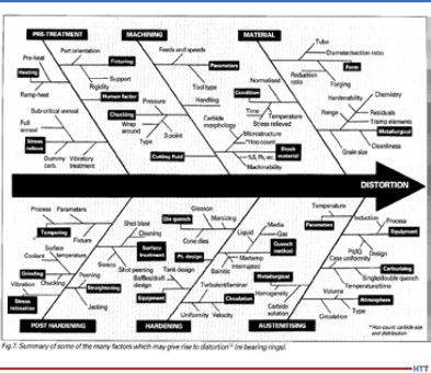
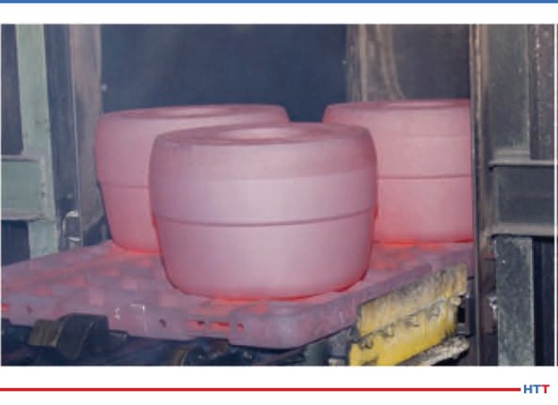
One of the other changes that was pretty significant—though I don't think it will affect the industry all that much—is that now we require thermocouples to be accurate to what's called “special limits of error.”  The previous revision allowed for two different types: You were allowed special limits of error, which the accuracy is + or –2 degrees Fahrenheit, or .4% of reading.  That was only required for a system accuracy test sensor or for a sensor that was being put in a Class 1 or 2 furnace.  All other sensors, such as TUS of load sensors, and class 3-6, we allowed for standard limits of air, which was + or –4 or .75% of reading, whichever is greater.

We did some polling of major thermocouple suppliers out there. With my personal experience and that of some of the other people on the committee, we kind of said, “Hey, you know what? No one really orders the junky stuff, the standard limits; everyone orders special limits of error.”  James LaFollette said, “Come to think of it, I don't think I've ever seen a purchase order that says give me the crappy stuff.  We all order special limits.”  So that's what we discovered – that no one was ordering the bare minimum because there wasn't a price difference between the two.  Everyone had already been ordering the good stuff, so we just made that a little bit of a tighter requirement.  Again, I don't think it's going to affect any suppliers out there.

I think the biggest change, when it came to thermocouples and sensors, was a big restriction that we put on what's called “expendable test sensors.”  This was dealing with the base metal thermocouples.  Base metal thermocouples are type K, type J, type T, type N, type M, and a couple other type base metals.

Click to read the Heat Treat Today article on thermocouples.

Primarily in the heat treating and thermal processing world, you pretty much see the K, J, N, and T.  We had done some studies as a sub-team within 2750 to look at the drifting of thermocouples, that is, where thermocouples start to lose their accuracy.  In the previous revision, we had some provisions in place that allowed people to use these expendable thermocouples that were attached to a temperature uniformity survey rack and were preserved.  They could use them up to three years or 90 uses when below 1200 degrees.  We thought that seemed kind of excessive on a 20-gauge wire that is covered with fiberglass coating.  They're probably not going to hold up, but maybe we should see if there is any drifting of these thermocouples.  So, we had one of the major thermocouple suppliers, Cleveland Electric Lab, run some drift studies on type K thermocouples, and we found out that these wires were actually starting to drift after three or four runs.  The drift study included a cycling test where they ran it up to temperature and back down 30 different times.  We asked, “Why don't we try to simulate how these thermocouples are going to interact coming in and out of thermal processing equipment?  Why not pull them out every single time and do it that way?”  Again, we found that thermocouples were drifting even further and even quicker.

At this point we decided we better put a restriction on this, and that gave the biggest uproar regarding the reuse of these thermocouples.  Previous drafts before the final release of the spec was, if it's used above 500, your expendable wire is one and done above 500 degrees.  A lot of the suppliers out there came screaming and said this is going to cost us millions and millions of dollars more in thermocouples.  But we stood firm and said, “Hey look, if you're using these test thermocouples to validate your furnaces, either through a system accuracy test or uniformity survey, you really do not know what your error of that wire is after the first use.”

Most of the major thermocouple suppliers will even state on certifications that they will only guarantee accuracy at the time of calibration.  Once it goes in a furnace, atmosphere and different conditions of the furnace will affect the wire.  We stood our ground, but we ended up backing off a little bit.  If you were using them strictly below 500, you're allowed to use them for 3 months (90 days) and you're going to have to keep a log.  If you're using them between 500 and 1200, we're going to allow you to use them for 90 days, but now you're only restricted to five usages.  And then again, above 1200, you use it once and throw it away.  That was probably the biggest hassle, trying to get that.  We did finally compromise on that three month or five usages.  I do see the burden on the suppliers because they were used to three years or 90 usages, so now it's down to three months or five usages.

DG:  I see on the chart that I've got here in front of me that base metal types of M, T, K, and E are all the three month or five use, but you've also got base metal type J and N which is three months or 10 uses.  But all of them, above 1200, one and done.

Table for SAT and TUS Sensor Reuse (photo source: Andrew Bassett, ATP)

AB:  Correct.  That's one of the things I was trying to explain to some of the suppliers that were having heartache about the original change of 500 one-and-done.  We only left it to the types M, T, K, and E; we always left this out of types J and N.  My personal experience with type J has been (and we've switched over to type J wire a while ago for testing below 1200 degrees),that it's a little bit cheaper in price than the type K wire, and there was always this allowance for doubling the amount of usage if you just switch over to type J or type N.

DG:  We have a few significant changes in the area of calibrations.  What's another area of change in this section?

AB:  One of the big things which really surprised me when we wrote it into the standard, but which was kind of overlooked by some of the suppliers, was the requirement of test instruments to have a .1 readability.  So when it deals with test instruments and also now data acquisition systems. Now, if you have a chart recorder that is on your furnace (most people are going to data acquisition systems, some sort of SCADA systems), that recorder must have a .1 readability.  That caused an uproar since that may create big changes.

Now, we don't put out these changes because we think it's a good idea; AMEC is data driven.  The big thing with the .1 readability is that we were actually fixing a flaw that has been in the spec since the first day it was written, when it was just rev. A.  We allowed for percentages of readings for your accuracy requirements.  Let's say, for instance, on your instruments that are on your furnace calibrated controller an if it's in Fahrenheit, you're allowed + or –2, but if it's in Celsius, it has to be + or – 1.1.  And if your instrumentation doesn't show .1 readability, how can you show compliance?  That question is one of the reasons—that is, fixing a flaw in specification.

(photo source: www.atp-cal.com/laboratory/)

But we also allow for percentage of reading, which is + or –2 Fahrenheit or 1.1 Celsius or .2 % of reading, whichever is greater.  Let's say you have a calibration point at 1400 degrees, you're actually allowed  an error of 2.8.  If you can't show that decimal point readability, how can you show compliance?  That was one of the biggest issues.

Originally, the first draft said all digital instruments need to be .1 readability and then we backed that off to only say that the data acquisition system had to be .1 readability.  At the end of the day, the recorders or the data acquisition system is the proof.  As long as that shows the tenth of degree of readability, and it meets the requirements, then you're good to go there.

We did look at how many customers are already using digital data acquisition systems through NADCAP.  There's actually a NADCAP checklist question that talks about chart speed verification, and if you answer that “N/A” then you obviously have digital data acquisition.  At that time, we did look at that data and 78% of the NADCAP heat treating suppliers out there already had paperless systems.  On top of that, two years after the release of 2750F, so as of June 29, 2022, you're not allowed to have paper chart recorders anymore.  Everything is pushed to a digital data acquisition system 2 years after the release of this spec.  I'd say, that's another one of the bigger changes when it deals with the instrumentation.

So the biggest changes are the .1 readability for your chart papers and the two years after the release requirement to go with a paperless system.

DG:  Now question three: What are the changes that were made in the calibration section?

AB:  There were a few changes when it came to calibration.

One of the things we added this time was the calibration of timing devices.  A lot of facilities have timers or clocks that they're basing their times and temperatures, and again, there was no requirement to calibrate this.  Therefore, we added a whole section on calibration of timing devices.

There was some push back on that.  Certain people, who have suppliers who use certain control operated by computers and which are always synchronized in their server systems, asked if they were going to have to go out and buy calibrated stopwatches and sit at their PC to make sure it's within these new requirements.  We finally said, no, you don't have to do that, but if you can procedurally address how that whole system works—that your server is always verified—you would be okay as long as you procedurally address that.

Again, we were loose on the accuracy requirements.  Some of these external devices that you have only need to be calibrated every two years.  Comparing it to people's standards that they use—we personally do calibration of timers as well, and our standards are required to be calibrated every two years—we ended up just tossing these devices away because it's more expensive to send them back for recalibration than it is to buy new ones.  So, we gave some of the suppliers an easier way out.  But we just wanted to address, again, something that has never been brought up in the specifications, which, though not technically dealing in the pyrometry world, does sit on furnaces. We need to get these things looked at every now and then as well.

[blocktext align="left"]“So, we gave some of the suppliers an easier way out.  But we just wanted to address, again, something that has never been brought up in the specifications, which, though not technically dealing in the pyrometry world, does sit on furnaces.”[/blocktext]Some of the other changes come in the documentation.  We did change some things that need to be required for the documentation of your calibration results.  One of the things was that we need you to document the sensor that you're calibrating for that particular piece of equipment.  For instance, you have a vacuum furnace and most vacuum furnace control sensors are a noble metal type S or type R thermocouple, but then the load thermocouples that measure the parts inside might be set as type K or type N.  We just want you to denote that the control system is type S and the load thermocouples are type K.  Not real big game changers, it's not going to cause too many issues out there from the supplier base, it's just adding basically another column in your calibration reports to say what sensor you're calibrating.

We didn't go too overly crazy on the calibration portion.  The one thing, kind of in the calibration field, is we did add a new instrumentation type.  When you look at thermal processing equipment, it's broken down into two different sections.  You have your furnace classification which is your uniformity tolerance and then you have what's called your instrumentation type.  You have class 1 - 6 and you have instrumentation A – E, now instrumentation D+.  This was more for Safron Aerospace.  Cyril Vernault was very adamant that we add this D+ instrumentation because Safron's specifications state that they want this extra sensor that is basically 3 inches away from the controlling sensor, so they can measure if there is a big difference between these two sensors to determine if there is drifting of your thermocouples.  So we added this new D+ instrumentation.  We didn't realize this was big over in Europe, but it was nice to have someone like Cyril say that a lot of European suppliers use this and that he’d like to see it in AMS2750.  Again, having this broad range of people on the specification helped us find out what's going on in different parts of the world.

DG:  How about we close with the fourth part of thermocouples?  Could you delve into the expanded section on offsets?

AB:  Absolutely.  Always one of the areas, especially when it comes to NADCAP audits, is the use of offsets.  We basically broke it down into two different types of offsets that are allowed.  We have what's called a correction offset, which is basically either a manual or electronic means to bring an instrument back to a nominal temperature.  And we have a modification offset, which is just the opposite.  It takes either a manual or electronic offset or a shift in the temperature to bring it away from nominal.  There are different ways that people have used these offsets.  For instance, let’s say you go into a facility and you're doing your calibration of a controller, and the instrument is off linear by two degrees.  People would use the offset to bring the instrument back a nominal temperature.  Instead of maybe doing a full factory calibration, they would just go into the instrument, hit some magic buttons, and (say I need to offset it -2 because my instrument was two degrees high) set a two degree correction offset.

A modification offset generally is only going to be used for when you're doing a temperature uniformity survey.  Let's say it is skewed to one side of your temperature median. For instance, (I always like to use this in my pyrometry training class), we know temperature uniformity and I go in and do a temperature uniformity on your furnace at 1000 degrees.  I have to hold it to be + or –10.  When I get my final results and I look at everything with all my calculations, I have a survey that actually comes out to be 992 – 998 degrees.  It's well within the + or –10, but it’s skewed down to the lower end.

So, there's different things you can do to try to correct that. Maybe change air flow, or thermocouple location, but a lot of time, what happens is you get a furnace that was made in the 1940s and you're trying to make it comply to 2020 specifications.  The only thing you can do is go in and shift the controller away from the nominal to actually make it read hotter.  In this example that I'm giving you, what I would do is go in and put in an electronic offset and tell the controller to read colder now, as I will drive more heat into the furnace.  So, I go in and put a -5 degree offset into the control and now, in theory, when you do the survey,  you're shifting that temperature up by five degrees.  Now if you look at that split, it would be 997 – 1003—it’s more centered around your set point temperature.  That would be what's called a modification offset.  You're taking that TUS distribution and skewing it to better center around the set point.

We really did some “spelling” on this: we put some maximums, the amount of offsets that are allowed as we don't want people to go too crazy on these things, so we did put some offsets in there.  But I think we did a great job of trying to spell out what these offsets are being used for, how you're supposed to document them, and make sure that you're consistent with your practice every time.  Again, procedures will have to be written to fully understand how you're going to do the offset.  Am I going to put it electronically?  Am I going to do a manual offset, just shift my temperature up five degrees because I know my furnace is cold by five degrees?  I think with that whole new section in there, I think we did a good job of spelling that out for the suppliers.

DG: Thanks so much, Andrew for joining us on the podcast.

AB: Thanks for having me, Doug. Looking forward to chatting more with you about AMS2750F.

You can reach out to Andrew Bassett at https://www.atp-cal.com/contact/.

Doug Glenn, Publisher, Heat Treat Today

Doug Glenn, Heat Treat Today publisher and Heat Treat Radio host.


To find other Heat Treat Radio episodes, go to www.heattreattoday.com/radio and look in the list of Heat Treat Radio episodes listed.

Heat Treat Radio #38: Andrew Bassett on AMS2750F (Part 1 of 3) Read More »