INSTRUMENTATION TECHNICAL CONTENT

Digitalization Propels Heat Treating to Industry of the Future

If you work in a standards-driven industry, you may already feel the imperative of digitalization. In today’s Technical Tuesday, Mike Loepke, head of Nitrex Software & Digitalization, posits how, even if you aren’t necessitated to track compliance digitally, you are probably looking to synthesize and leverage the strengths of multiple advanced operations — furnace and process record-keeping, knowledge of furnace past operations, juggling different new equipment capabilities — across just one platform. In other words, you are looking to bring digitalization system management to your operations.

This informative piece was first released in Heat Treat Today’s December 2024 Medical & Energy Heat Treat print edition.


The Future of Heat Treatment Relies on Digitalization

The ultimate goal for heat treaters, whether commercial or captive, is to uphold the quality of their product and meet client expectations while remaining profitable. Digitalization supports these efforts as it synthesizes and presents detailed, transparent, and accessible data that allows heat treaters to better manage their equipment, processes, and product quality. In addition, the collection of detailed information can serve as a database of knowledge to be used by the next generation of heat treaters, supporting future viability and advancement in the field.

There are necessary steps to take to establish a digital solution and essential components to look for when choosing a software platform that assists heat treaters in optimizing equipment and processes, effectively creating the digitalization of the heat treat operations. Let’s explore these now.

How Digitalization Optimizes Heat Treatment Processes

Digitalization in the heat treatment industry relies on the integration of industrial internet of things (IIoT) technologies with traditional and modern heat treatment processes. Using enabling devices such as sensors, modern connectivity methods, analytics, machine learning, and IIoT software platforms, it is possible for heat treaters to collect and process data that, after analysis, drives informed decisions to optimize equipment, processes, and product quality. To put a finer point on it, digitalization occurs when a manufacturing system is digitally integrated to capture and preserve human experience and knowledge, forming a holistic virtual representation of heat treat operations.
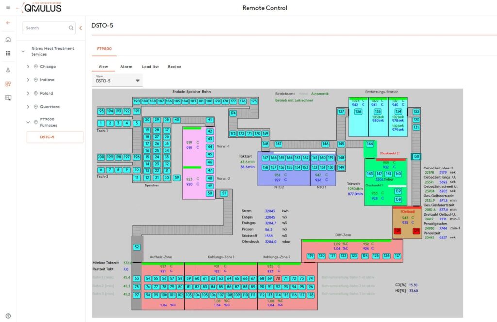
Figure 1. QMULUS Shop Layout enables visual inspection of the current production status, the location of goods and parts, as well as the real-time status of assets and their ongoing processes.
Source: Nitrex

While digitalization varies from industry to industry and plant to plant, there are some common ways in which heat treaters can employ digital technologies to build such a system. Firstly, digitally integrated solutions can optimize process management and control. For example, when a sensor detects a temperature anomaly during a heat treatment process, the integrated software platform picks up that reading, analyzes it in real time, recognizes it as an error based on historical data or programmed parameters, and alerts the operator.

This integration also facilitates predictive, condition-based maintenance. For example, if collected data and analysis suggests that a furnace is behaving abnormally, the system can automatically generate a work order along with a list of potential failure causes, so that a technician can troubleshoot, identify, and correct small issues — such as a failing thermocouple — before they impact quality or result in equipment failure. By addressing these proactively, heat treaters can avoid extended periods of costly unplanned downtime and ensure continuous operation.

Secondly, artificial intelligence through machine learning plays a crucial role in optimizing quality control in a digitalized system. By analyzing data collected during heat treating processes, it learns to detect patterns and identify anomalies. As in the examples above, this capability enables the system to identify deviations from the desired outcomes, allowing heat treaters to quickly rectify any issues before they impact quality.

Figure 2. The heart of the IIoT data platform needs to be thoughtfully planned and designed. Illustrated are 5 steps to follow to ensure the cloud data system properly engages with the data generated from your specific heat treat operations, ultimately delivering actionable insights. Step 1 depicts the various data sources; Step 2 shows the data transformation, integration, and processing stages; Step 3 highlights the central QMULUS database where data is indexed and organized; and Steps 4 and 5 demonstrate how data is further processed, distributed, and accessed by different end-users.
Source: Nitrex

Thirdly, algorithms can be programmed into a comprehensive management system to identify the most energy-efficient operating conditions for the heat treating process, helping heat treaters reduce their carbon footprint, minimize energy costs, and comply with sustainability goals.

In addition to these types of operational advantages, digitalization technologies can also be used to create a database of knowledge before experienced operators and experts leave the workforce. Traditionally, a handful of experts in the plant oversee the furnaces and equipment and understand how to best control and maintain them based on experience. However, passing down this knowledge to the next generation of heat treaters can take years, which may not be possible due to a company’s workflow demands and cost pressures. Digitalization addresses this challenge by creating a streamlined and accessible database of knowledge, offering less experienced operators and technicians immediate access to detailed information about what may be happening in the equipment or process for an issue at hand. This ensures that essential insights are not lost and enables quicker problem-solving and decision-making on the shop floor.

Making the Digitalization Transformation

While digitalization presents obvious advantages, the heat treatment industry, often conservative in its approach to technology, has some initial work and investment required before realizing the full benefits.

Going “paperless” in order to unlock the full potential of the available data is an important first step. All reports, histories, drawings, and other paperwork associated with equipment, processes, maintenance activities, product quality, and other relevant information should be digitized to provide a comprehensive view of both historical and current data.

Connectivity and integration between machine and higher-level systems are essential for effective data acquisition, monitoring, and remote control. SCADA systems, Manufacturing Execution Systems (MES), and other higher-level systems are rich sources of machine and process data. Gathering and analyzing this data can provide actionable insights that operators can use to make smarter decisions about the control and maintenance of equipment and processes.
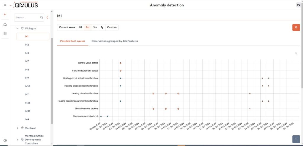
Figure 3. A comprehensive overview displays all detected control loop anomalies, indicating possible root causes as well as recommended actions. Incorporating feedback from the responsible maintenance personnel further improves accuracy and delivers more effective recommendations for future occurrences.
Source: Nitrex

Finally, just having data is not enough. The data must be accessible, transparent, and relevant to be valuable. Achieving a complete picture of all the collected data, known as data consolidation, is necessary.

To build an IIoT platform with a well-architectured data engine, heat treaters should begin by identifying and understanding the different sources of data provided by sensors and high-level systems. This involves integrating the data through interfaces adapted to the data type and source, as well as documenting the integrated data sources, data fields, and data streams. Next, a “data lake” should be created to store the collected raw data. From this foundation, a data warehouse can be established to store enriched or analyzed data, derived values, data models, and forecasts in an organized way. For heat treaters, this type of contextualized data might be grouped by parts, loads, or orders.

Once the data engine is in place, the information stored in the data warehouse must be presented in a way that makes sense to operators and technicians for them to make informed decisions for heat treatment processes. To facilitate this, a universal data interface should be considered.

Building from this well-architectured data engine, the IIoT platform can then be expanded with statistical analytics, remote monitoring, KPI tracking, machine learning, artificial intelligence, and other applications to optimize processes and increase profitability.

What Heat Treaters Need in a Digitalization Solution

Harnessing modern technologies tomake digitalization a reality presents heat treaters with the opportunity to implement a solution based on a complete and well documented data system. It also means that the solution creates a holistic solution to data analysis, interpretation, reporting, and action that supports the real-world actions of heat treaters on the plant floor and in the office.

For this reason, a digitalization solution that has cloud and on-premises allows real-time access to analysis and alert messages for operators on the floor as well as managers who are away from the plant, ensuring quick problem-solving and maximum uptime in the event of process or machine issues.

Additionally, heat treaters should look for a solution that offers the freedom to integrate all the various platforms and equipment from which data are gathered from. These may include relevant machinery and production data from the shop floor as well as third-party and custom controllers. This flexibility to synthesize information from multiple sources will ensure the digitalization efforts lead to a comprehensive solution with actionable process overviews, recipe control, batch tracking, and other customization options.

To further this intent of a holistic solution, heat treaters should consider various data capabilities with different portal views, such as a manufacturer portal, a plant portal, and a client portal. However, considering the historic value of a comprehensive software solution, it may be worthwhile to consider how each user could transfer direct feedback and add new rules into the system, creating a repository of knowledge that bridges the knowledge of outgoing generations to future heat treaters.

Finally, any platform that directs the digitalization of a plant must prioritize robust security measures. Several features to look for are:

  • enhanced encryption standards to keep data confidential and tamper-proof during transmission and storage;
  • secure protocols based on industry best practices to safeguard data integrity;
  • a granular access control system (ACS) to allow IT administrators to define and manage user permissions of authorized personnel, thereby minimizing the risk of data breaches and unauthorized data manipulation; and
  • intrusion detection and prevention systems to continuously monitor network and system activities, enabling instant identification and mitigation of suspicious behavior. This serves as an additional layer of defense against potential cyber threats.

Beyond the software setup, be sure to use best practices by conducting regular security audits to assess the platform’s vulnerabilities and ensure compliance with evolving cybersecurity standards. While digitalization of heat treat operations may seem like a task for the next generation to complete, secure software options that integrate the hard work of digitizing plant activities can make this endeavor just a step away.

About the Author:

Mike Loepke
Head of Nitrex Software & Digitalization
Nitrex

Drawing from a background in Mathematics and Physics, coupled with extensive R&D experience and metallurgical modeling, Mike Loepke specializes in AI and process prediction. He has led Nitrex’s initiative in developing QMULUS, a pioneering IIoT cloud-based platform. Mike’s relentless pursuit of knowledge keeps him at the forefront of evolving technology.

.

For more information: Contact Mike at mike.loepke@nitrex.com


Digitalization Propels Heat Treating to Industry of the Future Read More »

Ask the Heat Treat Doctor®: What Does “Bright and Shiny” Really Mean?

The Heat Treat Doctor® has returned to offer sage advice to Heat Treat Today readers and to answer your questions about heat treating, brazing, sintering, and other types of thermal treatments as well as questions on metallurgy, equipment, and process-related issues.


Contact us with your Reader Feedback!

Clients often want to know or specify that their component part surfaces are “bright” or “shiny” or “clean.” Other times they desire to have a surface condition that is “scale free” or “oxide free” after heat treatment. But how, if at all, can we quantify what these terms mean? Let’s learn more.

“Shiny” and “bright” are words that are highly subjective. This is often a source of confusion not only for the heat treater, but the manufacturer and, in some cases, even the end user of the products. Heretofore, the answer depended on one human being’s interpretation as opposed to another, and evaluations depend not only on the type of material but also the mill practices used, manufacturing methods employed, heat treatment processes, and the level and type of contamination introduced before and after processing.

Traditional Approach

Figure 1. Temper color chart atmosphere or tempering in air or an “inert” gas such as nitrogen. Source: Abbott Furnace Company

Traditionally, we have relied on color charts (Figure 1) to tell the approximate temperature at which discoloration took place, that is, an oxide formed on the (steel, stainless steel, or tool steel) surface of a component part. This method is still in use today when cooling parts in a furnace

As mentioned, the perception and interpretation of color is different for different people. Lighting (natural light or plant illumination), the environment in which one views color, eye fatigue, the age of the observer, and a host of other factors influences color perception. But even without such physical considerations, each of us interprets color based on personal perception. Each person also verbally describes an object’s color differently. As a result, objectively communicating a particular color to another person without using some type of standard is difficult.

There also must be a way to compare one color to the next with accuracy.

New Approach

Today, portable spectrophotometers (Figure 2) are available to measure color and help quantify brightness measurements. These types of devices are designed to meet various industry standards including:

  • Whiteness (e.g., ASTM E313, CIE)
  • Gray scale (e.g., ISO 105 staining, color change)
  • Opacity (e.g., contrast ratio, Tappi strength — SWL, Summed, Weighted Sum)
  • Yellowness (e.g., ASTM E313, D1925)
Figure 2. X-Rite MA-5 QC multi-angle spectrophotometer. Source: X-Rite

In simplest terms, a spectrophotometer is a color measurement device used to capture and evaluate color. Every object has its own reflectance, or the amount of light it reflects, and transmittance, or the amount of light it absorbs. A reflectance spectrophotometer shines a beam of light and measures the amount of light reflected from different wavelengths of the visible spectrum, while a transmission spectrophotometer measures how much light passes through the sample. Spectrophotometers can measure and provide quantitative analysis for just about anything, including solids, liquids, plastics, paper, metal, fabric, and even painted samples to verify color and consistency.

Spectrophotometers provide the solution to the subjective problem of interpreting the color of the surface of a component part that has been heat treated, brazed, or sintered because they explicitly identify the colors being measured; that is, the instrument differentiates one color from another and assigns each a numeric value.

As an example, the brightness of steel tubes annealed in a rich Exothermic gas atmosphere was measured against tubes that had not been processed (Figure 3). Having this definite measurement of the surface changes allowed the heat treater to provide their client with a definitive statement on the change after processing.

CIE Color Systems

The Commission Internationale de l’Eclairage (CIE) is an organization responsible for international recommendations for photometry and colorimetry. The CIE standardized color order systems include specifying the light source (illumination), the observer, and the methodology used to derive values for describing color, regardless of industry or use case.

Though spectrophotometers are the most common, for some applications colorimeters can also be used, but these are in general less accurate and less suitable for a heat treat environment.

There are three primary types of spectrophotometers on the market today used for print, packaging, and industrial applications: traditional 0°/45° (or 45°/0°) spectrophotometers, primarily used for the print industry; sphere (or diffuse/8°) spectrophotometers, primarily used in the packaging industry; and multi-angle (MA) spectrophotometers, for use in industrial environments. These instruments capture color information, and in some cases can capture appearance data (e.g., gloss).

Multi-angle (MA) spectrophotometers are best suited for measurements involving special surface effects, such as those found on metal surfaces and coatings and include those with surface contaminants and even can quantify cosmetic appearance. These are typically used on the shop floor, in the lab and in quality control, and even can be found in shipping areas.

MA spectrophotometers require users to verify five or more sets of L*a*b values or delta these terms). They typically have an aperture size of 12 mm, which is too large for measuring the fine detail that occurs in many small-scale industrial applications. Primary illumination is provided at a 45° angle. Some models have secondary illumination at a 15° angle.

Figure 3. Example of a product test — color and oxidation level test. Source: X-RIte

An application example for an MA spec trophotometer lies in their use for collecting colorimetric data on special effects coatings in the automotive industry, capturing reliable color data in cases where special effect coatings are used.

Final Thoughts

In this writer’s opinion, a spectrophotometer should be in every heat treat shop! You will be doing both yourself and your customers a valuable service and take the guesswork out of one of the most commonly asked questions – is it bright?

References

  • Herring, Dan H. Atmosphere Heat Treatment Volume 1. BNP Media, 2014.
  • X-Rite Pantone. “A Guide to Understanding Color.” Accessed October 10, 2024. https://www.xrite.com/learning-color-education/whitepapers/a-guide-to-understanding-color.
  • X-Rite Panatone. “Tolerancing Part 3: Color Space vs. Color Tolerance.” Accessed October 10, 2024. https://www.xrite.com/blog/tolerancingpart-3.
  • X-Rite Pantone. “X-Rite Portable Multi Angle Spectrophotometers.” Accessed October 10, 2024. https://www.xrite.com/categories/portable-pectrophotometers/ma-family.

About the Author

Dan Herring
“The Heat Treat Doctor”
The HERRING GROUP, Inc.

Dan Herring has been in the industry for over 50 years and has gained vast experience in fields that include materials science, engineering, metallurgy, new product research, and many other areas. He is the author of six books and over 700 technical articles.

For more information: Contact Dan at dherring@heat-treat-doctor.com.

For more information about Dan’s books: see his page at the Heat Treat Store.


Find Heat Treating Products And Services When You Search On Heat Treat Buyers Guide.Com


Ask the Heat Treat Doctor®: What Does “Bright and Shiny” Really Mean? Read More »

A New Era: Tracking Quality Digitally

What are advanced management systems and how does deep integrative system management software help automotive heat treaters improve processes while saving on time and unnecessary expenses? Explore the future of software technology for the management of heat treating operations in this Technical Tuesday by Sefi Grossman, founder and CEO of CombustionOS.


The heat treating industry is on the brink of a technological transformation. Just as the momentous adoption of websites and emails transformed the nature of work for manufacturers, the advanced software systems are thrusting us into a new era of simplicity, automation, and deep integrations.

This article explores how advanced systems — an application of ERP (enterprise resource planning) and MES (manufacturing execution systems) combined with the power of AI — is revolutionizing facility operations, enhancing quality, efficiency, and profitability.

What Are Advanced Systems?

Advanced systems simplify, streamline, and automate operations by lifting the data burden off of plant personnel. While most existing systems focus on the part inventory workflow, more advanced systems go beyond by directly integrating into the heat treat process to track at bin/tray/tree level.

This requires real-time scheduling control, barcode scanning, digitizing recipe and process (no more paper), and direct sensor/PLC integration. Because of its critical nature, an advanced system is most likely an on-premise and cloud “hybrid solution” that is not crippled by internet connectivity issues. This allows it to still utilize rapidly evolving cloud systems that provide external services like messaging, big data storage, and AI to name a few.

Precise Processing

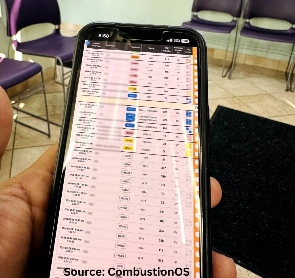
Figure 1. CombustionOS developers spend extensive time with operators and plant managers to create interfaces that are intuitive and easy to use. Pictured is access to job data stats from a mobile device being used outside of the manufacturing plant.

Repeatable, accurate methods to ensure optimal time, temperature, and atmosphere of the decided heat treatment processes are possible with advanced systems.

Utilizing existing sensors and hardware interfaces, data is collected in short intervals, transformed into meaningful data formats, and stored in a database. Network technologies such as HTTP, Modbus, and other analog to AI technologies make this possible with minimum additional hardware. The data is managed locally on the facility network, and synchronized with cloud services for further processing, analysis, and long-term history storage.

With a close monitoring of all these variables, facilities can tighten acceptable specification ranges. Deep integration with equipment ensures that data flows seamlessly from sensors and devices to the central system.

This real-time data collection and processing enables facilities to monitor operations continuously and make informed decisions quickly. For example, integrating data from temperature sensors, pressure gauges, and other monitoring devices ensures that all critical parameters are tracked and managed effectively. Additionally, if a temperature reading deviates from the acceptable range, the system can immediately alert the relevant personnel, allowing them to take corrective action before it becomes a critical issue.

 In addition to quality assurance, integrated artificial intelligence tools optimize job scheduling. Unlike traditional date/time calendar methods, AI systems predict job completion times based on real-time process data. This is particularly useful for roller furnace setups, where continuous processing occurs, but it is also beneficial for batch furnaces. Optimized scheduling improves resource allocation and operational efficiency, ensuring that jobs are completed on time and to the required specifications. The difference between a “calculation algorithm” and AI is that, with AI, you do not have to pre-program it. It automatically learns and adjusts for known variability in your hardware and even the personnel that are operating the equipment.

Finally, the automation of these systems captures and records all necessary information accurately. This reduces the risk of non-compliance, improving the overall quality of the final product. For example, a Detroit-based heat treating facility reported that accessing real time data to ensure compliance with industry standards has allowed them to spend 40% less time on documentation tasks.

Figure 2. Having increased control over the process gives more peace of mind to operators that components perform as needed.

Alleviating Burden on Maintenance and Inventory

Predictive maintenance is one of the most significant applications of AI in the heat treating industry. Traditional maintenance schedules are often based on fixed intervals, which can lead to unnecessary downtime or unexpected failures. AI driven predictive maintenance, on the other hand, uses real-time data to determine the optimal times for maintenance activities. This approach not only reduces downtime but also extends the lifespan of equipment.

A Detroit-based heat treating facility implemented an AI-driven predictive maintenance system (PMs) and saw a 25% reduction in equipment downtime. By analyzing data from critical parts, inventory, process tracking history, and various sensors, the AI system could predict when components were likely to fail, allowing the maintenance team to inspect and address issues proactively beyond their standard PMs. This not only improved operational efficiency, but also saved significant costs associated with emergency repairs and unplanned downtime.

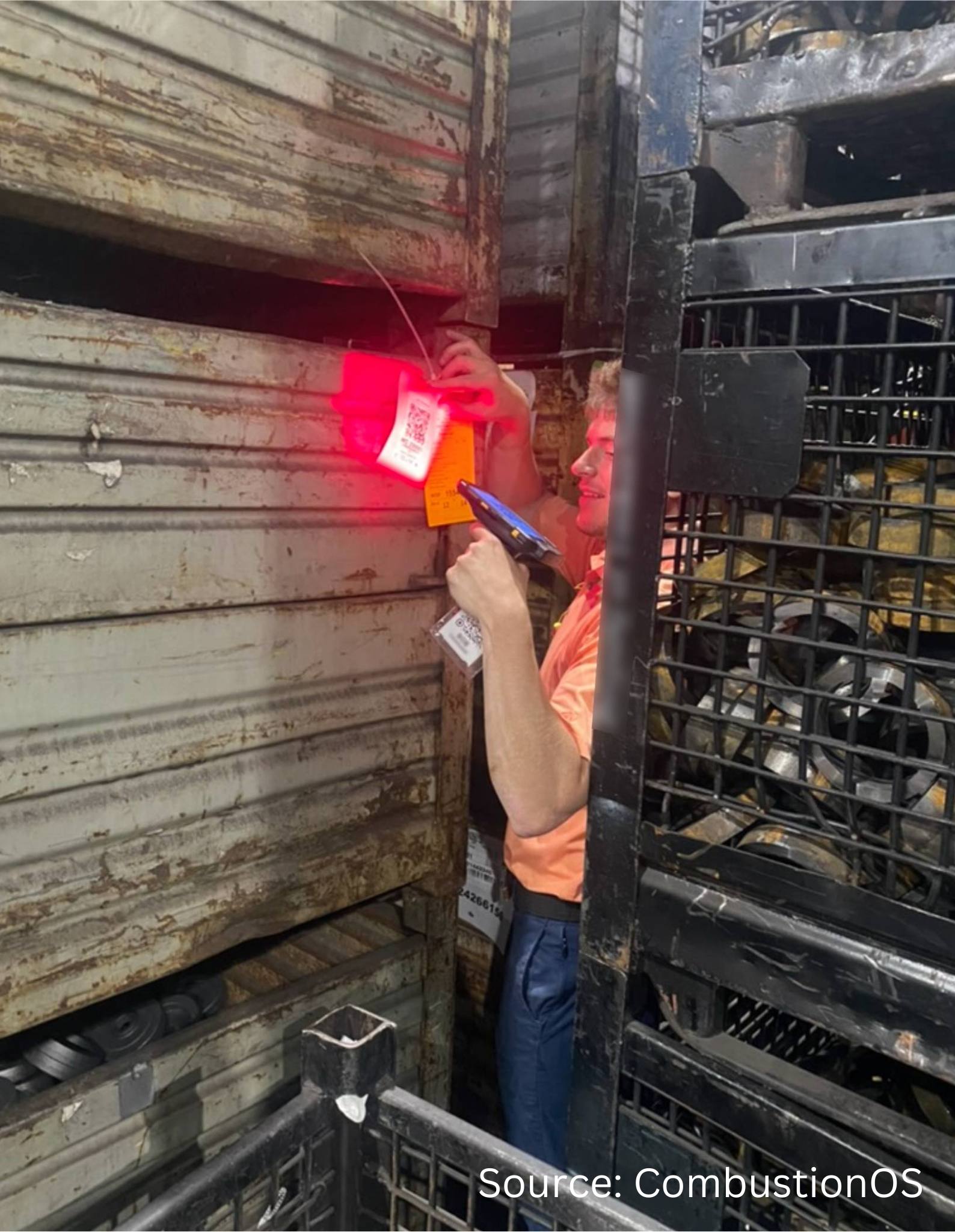
Additionally, the integration of QR codes for inventory and process tracking enables quick and accurate data entry compared to manual logging. For instance, when racking parts out of bins, operators can simply scan QR codes, which automatically update the system with the relevant information. This not only speeds up the process but also minimizes the chances of human error.

Reducing Operational Costs

The adoption of advanced ERP and MES systems has led to substantial cost savings for many facilities. These systems reduce operational costs through the implicit automated integrations that technologies like CombustionOS bring. Here are just a few ways that operational costs have been cut:

  • Decreasing shipping and receiving management from three to just one employee
  • Minimizing rework costs by timely process alerts
  • Reducing personnel by replacing constant manual oversight with accurate, digital tracking systems
  • Lowering administrative costs by utilizing a more efficient and accurate invoice automation platform

Case Study: A client reported comprehensive cost savings, including a 20% reduction in shipping and receiving time, fewer logistics and furnace operators needed, a 33% decrease in rework costs, a 15% savings in maintenance costs, and a 25% reduction in accounting overhead. These efficiencies translate into substantial payroll savings and improved profitability.

How To Implement

Figure 3. When racking parts out of bins, operators can simply scan QR codes, which automatically update the system with the relevant information.

One of the most significant advancements in heat treating technology is the deep integration with various equipment types. Unlike traditional ERP systems, which often lack true integration, advanced systems work backwards from equipment data, building ERP functionalities around this integration to ensure seamless and accurate data flow.

First, there are advanced systems that can handle data from both digital and analog sensors. So, for heat treaters who are juggling a variety of sensors and systems, looking for an integrative advanced system that has adaptability will ensure compatibility with existing equipment while keeping an eye on cost. Facilities can continue using their current equipment while benefiting from advanced monitoring and control capabilities.

Second, advanced ERP/MES systems can take collaboration with multiple vendors. Rather than uproot current systems and relationships, work with an advanced systems provider who is able to collaborate with other software and systems. Advanced ERP/MES systems provide comprehensive solutions that include deep equipment integration and full ERP functionalities. This approach reduces the complexity and cost of integration, ensuring that all components work together seamlessly.

Key Applications

Most operations in a heat treat department will benefit from advanced systems due to the time-saving automations that the system integrates. But many heat treaters are looking to adapt and integrate older systems and often more complex designs, like roller hearth furnaces. Here are some steps that experts will take to guide you through to make the digital integration smooth and effective:

  1. First, it is important to understand you don’t need to boil the ocean. Starting with a more advanced inventory tracking system that employs barcodes can set the underpinnings for a more integrated system while providing immediate benefits to your logistics.
  2. Then, it is also key to get a deep understanding of your current process and map out your operational workflow. Using a flowchart program helps
    visualize the process to make sure all stakeholders are on the same page.
  3. Some aspects of your current process are probably outdated (perhaps created by someone who is no longer at the company), while others are key to the core of how you operate. Understanding the difference is crucial to make sure you unlock potential automation without disturbing your core process and flow.
  4. You’ll then need to prepare every required form, document, chart etc. that you use in the operation. For process control, recipes, and lab testing, provide many parts/iterations to capture the complexity.
  5. Finally, take inventory of any existing digital systems you have adopted, like inventory tracking, spreadsheets, or custom software. The existing system
    network, including servers, Wi-Fi setup, and hardware (PCs, printers, scanners, etc.) will be utilized as much as possible in the transition to reduce the need to purchase and set up different equipment.

Conclusion

The future will require constant innovations and thoughtful leveraging of increasingly advanced systems. Unlike static, homegrown, or “pieced together” solutions, the most advanced systems are constantly updated with new features, ensuring they remain at the cutting edge of technology. Engaging directly with plant personnel to understand their needs and challenges allows systems like CombustionOS to evolve and improve continuously.

The heat treating industry is on the cusp of a technological transformation, driven by advancements in ERP, MES, and AI. These technologies offer the potential to enhance quality, efficiency, and profitability, making them essential for the future of manufacturing. By embracing automation, integrating advanced AI capabilities, and committing to continuous innovation, the industry can achieve new levels of operational excellence.

About the Author:

Sefi Grossman
Founder & CEO
CombustionOS
Source: Author

Sefi Grossman has been at the forefront of technology revolutions for the past two decades and has been leading the technology company CombustionOS for nearly seven years.


For more information: Contact Sefi at sefi@combustionos.com.


Find Heat Treating Products And Services When You Search On Heat Treat Buyers Guide.Com

A New Era: Tracking Quality Digitally Read More »

Overcoming Quality Challenges for Automotive T6 Heat Treating

Three elements in the T6 aluminum heat treatment process — high temperature solution heat treatment, drastic temperature change in the water quench, and a long age hardening process — challenge accurate temperature monitoring. Thru-process technology gives in-house heat treaters the power to control these variables to overcome the unknowns. In the following Technical Tuesday article, Dr. Steve Offley, “Dr. O”, product marketing manager at PhoenixTM, examines the path forward through the challenges of aluminum heat treating.


Aluminum Processing Growth

In today’s automotive and general manufacturing markets, aluminum is increasingly becoming the material of choice, being lighter, safer, and more sustainable. Manufacturers looking to replace existing materials with aluminum are needing new methodology to prove that thermal processing of aluminum parts and products is done to specification, efficiently and economically.

To add strength to pure aluminum, alloys are developed by the addition of elements dissolved into solid solutions employing the T6 heat treatment process (Figure 1). The alloy atoms create obstacles to dislocate movement of aluminum atoms through the aluminum matrix. This gives more structural integrity and strength.

FIgure 1. Critical temperature phase transitions of the T6 aluminum heat treatment process
Source: PhoenixTM

Process temperature control and uniformity is critical to the success of T6 heat treat to maximize the solubility of hardening solutes such as copper, magnesium, silicon, and zinc without exceeding the eutectic melting temperature. With a temperature difference of typically 9–15°F, knowing the accurate temperature of the product is essential. Control of the later quench process (Figure 1, Phase 3) is also critical not only to facilitate the alloy element precipitation phase but also to prevent unwanted part distortion/warping and risk of quench cracking.

T6 Process Monitoring Challenges

The T6 solution reheat process comes with many technical challenges where temperature profiling is concerned. The need to monitor all three of the equally important phases — solution treatment, quench, and the age hardening process — makes the trailing thermocouple methodology impossible.

Figure 2. Thru-process temperature monitoring of the three T6 heat treatment phases
Source: PhoenixTM

Even when considering applying thru-process temperature profiling technology, sending the data logger through the process, protected in a thermal barrier (Figure 2), the T6 heat treat process comes with significant challenges. A system will not only need to protect against heat (up to 1020°F) over a long process duration but also withstand the rigors of being plunged into a water quench. Rapid temperature transitions create elevated risk of distortion and warping which need to be addressed to give a reliable and robust monitoring solution.

Certain monitoring systems can provide protection to the data logger at 1022°F for up to 20 hours (Figure 3).

Figure 3. Thru-process temperature profiling system installed in the product cage monitoring the T6 heat treatment (solution treatment, quench, and age hardening) of aluminum engine blocks

Thermal Protection Technology

To meet the challenges of the T6 heat treat process, the conventional thermal barrier design employing microporous insulation is replaced with a water tank design, with thermal protection using an evaporative phase change temperature control principle. Evaporative technology uses boiling water to keep the high temperature data logger (maximum operating temperature of 230°F) at a stable operating temperature of 212°F as the water changes phase from liquid to steam. The advantage of evaporative technology is that a physically smaller barrier is often possible. It is estimated that with a like for like size (volume) and weight, an evaporative barrier will provide in the region of twice the thermal protection of a standard thermal barrier with microporous insulation and heat sink. The level of thermal protection can be adjusted by changing the capacity of the water tank and the volume of water. Increasing the volume of water increases the duration at which the T6 temperature barrier will maintain the data logger temperature of 212°F before it is depleted by evaporation losses.

The TS06 thermal barrier design (Figure 4) incorporates a further level of protection with an outer layer of insulation blanket contained within a structural outer metal cage. The key role of this material is to act as an insulative layer around the water tank to reduce the risk of structural distortion from rapid temperature changes both positive and negative in the T6 process.

Figure 4. TS06 thermal barrier design showing water tank, housing the data logger at its core, installed within structural frame containing the insulation blanket surface layer; water tank shown with traditional compression fitting face plate seal
Source: PhoenixTM

Obviously, the evaporative loss rate of water is governed by the water tank geometry. A cube shaped tank will provide the best performance, but this may need to be adapted to meet process height restrictions. A TS06 thermal barrier with dimensions 8.5 x 18.6 x 25.2 inches (H x W x L) offering a water capacity of 3.5 US gallons provides 11 hours of protection at 1022°F. A larger TS06 with approximately twice the capacity 12.2 x 18.6 x 25.2 inches (H x W x L) and 7.7 US gallons gives approximately twice the protection (20 hours at 1022°F).

Innovative IP67 Sealing Design

Passing through the water quench, the data logger needs to be protected from water damage. This is achieved in the system design by combining a fully IP67 sealed data logger case and water tank front face plate through which the thermocouples exit. Traditionally in heat treatment applications, mineral insulated thermocouples are sealed using robust metal compression fittings. Although reliable, the compression seals are difficult to use, requiring long set-up times. The whole uncoiled straight cable length must be passed through the tight fitting which, for the 10 x 13 ft thermocouples, takes some patience. Thermocouples can be used and installed for multiple runs, if undamaged. Unfortunately, as the ferrule in the compression fitting bites into the MI cable, removal of the cable requires the thermocouple to be cut, preventing reuse.

To overcome the frustrations of compression fitting, an alternative innovative thermocouple sealing mechanism has been designed for use on the T6 thermal barrier (Figure 5).

Figure 5. TS06 thermal barrier IP67 bi-directional rubber gasket seal; installation of mineral-insulated (MI) thermocouples and RF antenna aerial

Thermocouples can be slotted easily and quickly, tool free, into a precision cut rubber gasket without any need to uncoil the thermocouple completely. The rubber gasket has a unique bi-directional seal, allowing both sealing of each thermocouple but also sealing of the clamp face plate to the data logger tray, which is then secured to the water tank with a further silicone gasket seal. The new seal design allows thermocouples to be uninstalled and reused, reducing operating costs significantly.

Accurate Process Data considerations

The T6 applications come with a series of monitoring challenges which need to be considered carefully to guarantee the quality of the data obtained. Although the complete process time of the three phases can reach up to 10 hours, it is necessary to use a rapid sample interval (seconds) to provide a sufficient resolution. The data logger is designed to facilitate this with a minimum sample interval of 0.2 seconds over 20 channels and memory size of 3.8 million data points, allowing complete monitoring of the entire process. A sample interval of 0.2 seconds provides sufficient data points on the rapid quench cooling curve. The high resolution allows full analysis and optimization of the quench rate to achieve required metallurgical transitions yet avoid distortion or quench cracking risks.

Employing the phased evaporation thermal barrier design, the high temperature data logger with maximum operating temperature of 230°F will operate safely at 212°F. During the profile run, the data logger internal temperature will increase from ambient temperature to 212°F. To allow the thermocouple to accurately record temperature, the data logger offers a sophisticated cold junction compensation method, correcting the thermocouple read out (hot junction) for anticipated internal data logger temperature changes.

Data logger and thermocouple calibration data covering the complete measurement range (not just a single designated temperature) can be used to create detailed correction factor files. Correction factors are calculated by interpolation between two known calibration points using the linear method as approved by CQI-9 and AMS2750G. This method ensures that all profile data is corrected to the highest possible accuracy. 

Addressing Real-Time, Thru-Process Temperature Monitoring Challenges

For a process time as long as the T6, real-time monitoring capability is a significant benefit. The unique two-way RF telemetry system used on the PhoenixTM system helps address the technical challenges of the three separate stages of the process. The RF signal can be transmitted from the data logger through a series of routers linked back to the main coordinator connected to the monitoring PC. The wirelessly connected routers are located at convenient points in the process (solution treatment furnace, quench tank, aging furnace) to capture all live data without any inconvenience of routing communication cables.

A major challenge in the T6 process is the quench step from an RF telemetry perspective. An RF signal cannot escape from water in the quench tank. To overcome this limitation, a “catch up” feature is implemented. Once the system exits the quench and the RF signal is re-established, any previously missing data is retransmitted guaranteeing full process coverage.

Process Quality Assurance and Validation

In the automotive industry, many operations will be working to the CQI-9 special process heat treat system assessment accreditation. As defined by the pyrometry standard, operators need to validate the accuracy and uniformity of the furnace work zone by employing a temperature uniformity survey (TUS).

The thru-process monitoring principle allows for an efficient method by which the TUS can be performed employing a TUS frame to position a defined number of thermocouples over the specific working zone of the furnace (product basket). As defined in the standard with particular reference to application assessment process Table C (aluminum heat treating), the uniformity for both the solution heat treatment and aging furnace needs to be proven to satisfy ±10°F of the threshold temperature during the soak time.

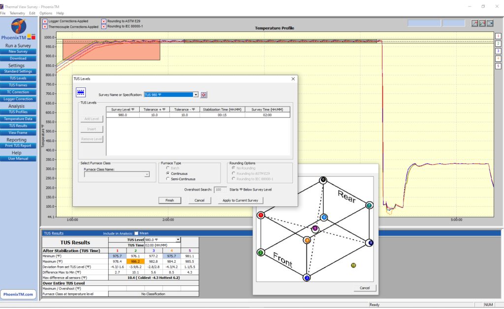
Complementing the TUS system, the Thermal View Survey software provides a means by which the full survey can be set up automatically allowing routine full analysis and reporting to the CQI-9 specification as shown in Figure 6.

Figure 6. View of TUS for T6 aluminum processing in Phase 1 Solution Re-heat
Source: PhoenixTM

Interestingly, a significant further benefit of the thru-process principle is that by collecting process data for the whole process, many of the additional requirements of the process Table C can be achieved with reference to the quench. From the profile trace, key criteria such as quench media temperature, quench delay time, and quench cooling curve can be measured and reported with full traceability during the production run.

Summary

To fully understand, control, and optimize the T6 heat treat process, it is essential the entire process is monitored. Thru-process monitoring solutions, designed specifically, allow not only product temperature profiling of all the solution heat treatment, water quench, and age hardening phases, but also comprehensive temperature uniformity surveying to comply with CQI-9.

About the Author:

Dr Steve Offley (“Dr O”), Product Marketing Manager, PhoenixTM

Dr. Steve Offley, “Dr. O,” has been the product marketing manager at PhoenixTM for the last five years after a career of over 25 years in temperature monitoring focusing on the heat treatment, paint, and general manufacturing industries. A key aspect of his role is the product management of the innovative PhoenixTM range of thru-process temperature and optical profiling and TUS monitoring system solutions.

For more information: Contact Steve at Steve.Offley@phoenixtm.com.


Find Heat Treating Products And Services When You Search On Heat Treat Buyers Guide.Com


Overcoming Quality Challenges for Automotive T6 Heat Treating Read More »
Traveling through Heat Treat: Best Practices for Aero and Auto

Thinking about travel plans for the upcoming holiday season? You may know what means of transportation you will be using, but perhaps you haven't considered the heat treating processes which have gone into creating that transportation. 

Today’s Technical Tuesday original content round-up features several articles from Heat Treat Today on the processes, requirements, and tools to keep planes in the air and vehicles on the road, and to get you from one place to the next. 


Standards for Aerospace Heat Treating Furnaces 

Without standards for how furnaces should operate in the aerospace, there could be no guarantee for quality aerospace components. And without quality aerospace components, there is no guarantee that the plane you're in will be able to get you off the ground, stay in the air, and then land you safely at your destination.

In this article, written by Douglas Shuler, the owner and lead auditor at Pyro Consulting LLC, explore AMS2750, the specification that covers pyrometric requirements for equipment used for the thermal processing of metallic materials, and more specifically, AMEC (Aerospace Metals Engineering Committee).

This article reviews the furnace classes and instrument accuracy requirements behind the furnaces, as well as information necessary for the aerospace heat treater.

See the full article here: Furnace Classifications and How They Relate to AMS2750

Dissecting an Aircraft: Easy To Take Apart, Harder To Put Back Together 

Curious to know how the components of an aircraft are assessed and reproduced? Such knowledge will give you assurance that you can keep flying safely and know that you're in good hands. The process of dissecting an aircraft, known as reverse engineering, can provide insights into the reproduction of an aerospace component, as well as a detailed look into the just what goes into each specific aircraft part.

This article, written by Jonathan McKay, heat treat manager at Thomas Instrument, examines the process, essential steps, and considerations when conducting the reverse engineering process.

See the full article here: Reverse Engineering Aerospace Components: The Thought Process and Challenges

Laser Heat Treating: The Future for EVs?

If you are one of the growing group of North Americans driving an electric vehicle, you may be wondering how - and how well - the components of your vehicle are produced. Electric vehicles (EVs) are on the rise, and the automotive heat treating world is on the lookout for ways to meet the demand efficiently and cost effectively. One potential solution is laser heat treating.

Explore this innovative technology in this article composed by Aravind Jonnalagadda (AJ), CTO and co-founder of Synergy Additive Manufacturing LLC. This article offers helpful information on the acceleration of EV dies, possible heat treatable materials, and the process of laser heat treating itself. Read more to assess the current state of laser heat treating, as well as the future potential of this innovative technology.

See the full article here: Laser Heat Treating of Dies for Electric Vehicles

When the Rubber Meets the Road, How Confident Are You?

Reliable and repeatable heat treatment of automotive parts. Without these two principles, it’s hard to guarantee that a minivan’s heat treated engine components will carry the family to grandma’s house this Thanksgiving as usual. Steve Offley rightly asserts that regardless of heat treat method, "the product material [must achieve] the required temperature, time, and processing atmosphere to achieve the desired metallurgical transitions (internal microstructure) to give the product the material properties to perform it’s intended function."

TUS surveys and CQI-9 regulations guide this process, though this is particularly tricky in cases like continuous furnace operations or in carburizing operations. But perhaps, by leveraging automation and thru-process product temperature profiling, data collection and processing can become more seamless, allowing you better control of your auto parts. Explore case studies that apply these two new methods for heat treaters in this article.

See the full article here: Discover the DNA of Automotive Heat Treat: Thru-Process Temperature Monitoring


Find heat treating products and services when you search on Heat Treat Buyers Guide.com


Traveling through Heat Treat: Best Practices for Aero and Auto Read More »
Heat Treat Radio #91: Understanding the ±0.1°F Requirement in AMS2750, with Andrew Bassett

Where did the ±0.1°F AMS2750 requirement come from and how should heat treaters approach this specification, an important change that entails major buy-in? Andrew Bassett, president and owner of Aerospace Testing and Pyrometry, was at the AMS2750F meeting. He shares the inside scoop on this topic with Heat Treat Today and what he expects for the future of this standard.

Heat Treat Radio podcast host and Heat Treat Today publisher, Doug Glenn, has written a column on the topic, which you can find here; read it to understand some of the background, questions, and concerns that cloud this issue.

Below, you can watch the video, listen to the podcast by clicking on the audio play button, or read an edited transcript.


The following transcript has been edited for your reading enjoyment.

Doug Glenn: Andrew Bassett, president and owner of Aerospace Testing and Pyrometry, Inc., somewhere in eastern Pennsylvania. We don’t know because you’re on the move! What is your new address, now, by the way?

Contact us with your Reader Feedback

Andrew Bassett: We are in Easton, Pennsylvania at 2020 Dayton Drive.

Doug Glenn: Andrew, we want to talk a bit about this ±0.1°F debate that is going on. It was actually precipitated by the column that I wrote that is in the February issue.

I just wanted to talk about that debate, and I know that you’ve been somewhat involved with it. So, if you don’t mind, could you give our listeners a quick background on what we are talking about, this ±0.1°F debate.

Andrew Bassett: To be honest with you, being part of the AMS2750 sub team, one of the questions came up for us during the Rev F rewrite was this 0.1°F readability — wanting to kind of fix this flaw that’s been in the standard ever since the day that AMS2750 came out. With instrumentation, for instance, you have ±2°F (the equivalent would be 1.1°C). At 1.1°C, the question became, If your instrumentation does not show this 0.1 of a degree readability, how can you show compliance to the standards?

Andrew Bassett
President
Aerospace Testing and Pyrometry
Source: DELTA H

Then, it morphed into other issues that we’ve had in the previous revisions where we talk about precise temperature requirements, like for system accuracy testing: You’re allowed a hard number ±3° per Class 2 furnace or 0.3% of reading, whichever is greater. Now, we have this percentage. With anything over 1000°F, you're going to be able to use the percentage of reading to help bring your test into tolerance. In that example, 1100°F, you’re about 3.3 degrees. If your instrumentation doesn’t show this readability, how are you going to prove compliance?

That’s what it all morphed into. Originally, the first draft that we proposed in AMS2750F was that all instrumentation had to have 0.1°F readability. We got some feedback (I don’t know if I want to say “feedback” or "pitchforks and hammers") that this would be cost-prohibitive; most instrumentation doesn't have that readability, and it would be really costly to go out and try to do this. We understood that. But, at the end of the day, we said: The recording device is your permanent record, and so that’s what we’re going to lean on. But we still had a lot of pushback.

We ended up putting a poll out to AMEC and the heat treating industry to see what their opinions were. We said that with the 0.1 readability (when it came to a percentage reading), recording devices would read hard tolerances. So, for instance, an SAT read at 3° would be just that, not "or .3% of reading."

There was a third option that we had put out to the community at large, and it came back as the 0.1° readability for digital recorders, so that’s where we ran with the 0.1° readability.

When it was that big of an issue, we didn’t make the decisions ourselves; we wanted to put it out to the rest of the community. My guess is not everyone really thought the whole thing through yet. Now people are like, ok, well now I need to get this 0.1° readability.

Again, during the meetings, we heard the issues. Is 0.1° going to really make a difference to metal? If you have a load thermocouple that goes in your furnace and it reads 0.1° over the tolerance, does it fail the load? Well, no, metallurgically, we all know that’s not going to happen, but there’s got to be a line in the sand somewhere, so it was drawn at that.

"...that hard line in the sand had to be drawn somewhere..."
Source: Unsplash.com/Willian Justen de Vasconcellos

That’s a little bit of the background of the 0.1° readability.

Doug Glenn: So, basically, we’re in a situation, now, where people are, in fact (and correct me if I’m wrong here),  potentially going to fail SATs or tests on their system because of a 0.1° reading, correct? I mean, it is possible, correct?

Andrew Bassett: Yes. So, when the 0.1° readability came out in Rev F, we gave it a two-year moratorium that with that requirement, you still had two more years. Then, when Rev G came out, exactly two years to the date, we still had a lot of customers coming to us, or a lot of suppliers coming back to us, and saying, “Hey, look, there’s a supply shortage on these types of recorders. We need to buy some time on this.” It ranged from another year to 10 years, and we’re like — whoa, whoa, whoa! You told us, coming down the pike before, maybe you pushed it down the road, whatever, probably Covid put a damper on a lot of people, so we added another year.

So, as of June 30th of 2023, that requirement is going to come into full play now. Like it or not, that’s where the standard sits.

Doug Glenn: So, you’re saying June 30th, 2023?

Andrew Bassett: Yes.

Doug Glenn Alright, that’s good background.

I guess there were several issues that I raised. First off, you’ve already hit on one. I understand the ability to be precise, but in most heat treatment applications, one degree is not going to make a difference, right? So, why do we push for a 0.1° when 1° isn’t even going to make a difference?

Andrew Bassett: We know that, and it’s been discussed that way. But, again, that hard line in the sand had to be drawn somewhere, and that was the direction the community wanted to go with, so we went with that. Yes, we understand that in some metals, 10 degrees is not going to make a difference, but we need to have some sort of line in the sand and that's what was drawn.

Doug Glenn: So, a Class 1. I was thinking the lower number was a tighter furnace. So, a Class 1 (±5), and you’re saying, that’s all the furnace is classified for, right, ±5? So, if you get a reading of 1000°, it could be 1005° or it could be 995°. Then, you’re putting on top of that the whole idea that your temperature reading has got to be down to 0.1°. There just seems to be some disconnect there.

So, that was the first one. You also mentioned the instrumentation. It’s been pointed out to me, by some of the instrumentation people, that their instruments are actually only reading four digits. So up to 99.9 you actually have a point, but if it goes to 1000°, you’re out of digits; you can’t even read that. I mean, they can’t even read that down to a point.

"So, if you get a reading of 1000°, it could be 1005° or it could be 995°."
Source: Unsplash.com/Getty Images

Andrew Bassett: Correct. On the recording side of things, we went away from analog instrumentation. The old chart papers, that’s all gone, and we required the digital recorders with that 0.1° readability, as of June 30th of this year.

Again, the first draft was all instrumentation. That would be your controllers, your overtemps, and we know that limitation. But everyone does have to be aware of it. We still allow for this calibration of ±2 or 0.2%. If you’re doing a calibration, let’s say, on a temperature control on a calibration point at 1600° and the instrument only reads whole numbers, you can use the percentage, but you would have to round it inward. Let’s use 1800°, that would be an easier way to do it. So, I’m allowed ±2 or 3.6° if I’m using the percentage of reading, but if the instrument does not read in decimal points for a controller or overtemp, you would have to round that down to ±3°.

Doug Glenn: ±3, right; the 0.6° is out the window.

Andrew Bassett: Correct. I shouldn’t say we like to bury things in footnotes, but this was an afterthought. In one of the footnotes, in one of the tables, it talks about instrumentation calibration that people need to be aware of.

Doug Glenn: Let’s just do this because I think we’ve got a good sense of what the situation is, currently. Would you care to prognosticate about the future? Do you think this is going to stand? Do you think it will be changed? What do you think? I realize you’re speaking for yourself, here.

Andrew Bassett: I’m conflicted on both sides. I want to help the supply base with this issue but I’m also on the standards committee that writes the standard. I think because we’re so far down the road, right now — this requirement has been out there since June 2022 — I don’t see anything being rolled back on it, at this point. I think if we did roll it back, we have to look at it both ways.

If we did roll this back and say alright, let’s just do away with this 0.1° readability issue, we still have to worry about the people processing in Celsius. Remember, we’re pretty much the only country in the world that processes in Fahrenheit. The rest of the world has been, probably, following these lines all along. If we rolled this back, just think about all the people that made that investment and moved forward on the 0.1° readability and they come back and say, “Wait a minute. We just spent a $100,000 on upgrading our systems and now you’re rolling it back, that’s not fair to us.”

At this point, with the ball already rolling, it would be very interesting to see when Nadcap starts publishing out the audit findings when it comes to the pyrometry and this 0.1° readability to see how many suppliers are being hit on this requirement and that would give us a good indication. If there are a lot of yeses on it then, obviously, a lot of suppliers haven’t gone down this road. My guess is, for the most part, anybody that’s Nadcap accredited in heat treating — and this goes across chemical processing, coatings, and a few other commodities — I think has caught up to this.

Personally, I don’t think this is going to go away; it’s not going to disappear. It’s going to keep going down this road. Maybe, if people are still struggling with getting the types of devices that can have that 0.1° readability, then maybe another year extension on it, but I don’t know where that is right now. I haven’t gotten enough feedback from aerospace customers that say, "Hey, I can’t get the recorder." I mean,

Doug Glenn: I just don’t understand, Andrew, how it’s even physically possible that companies can record something as accurately as 0.1° if the assembly or thermocouple wire is rated at ±2°? How is that even possible that you can want somebody to be accurate down to ±0.1° when the thing is only accurate up to ±2°?

Andrew Bassett: Right, I get that. We can even go a lot further with that and start talking about budgets of uncertainty. If you look at any reputable thermocouple manufacturer or instrument calibration reports that are ISO 17025, they have to list out their measurements of uncertainty, and that gives you only the 98% competence you’re going to be within that accuracy statement.

Yes, I get the whole issue of this .1° readability. There were good intentions were to fix a flaw, and it spiraled. We’ve seen where PLCs and some of these high logic controllers now can show the .1° readability, but they automatically round up at .5°. Are you now violating the other requirements of rounding to E29? Now, I think we’ve closed out the poll in the standard, but you’re right. We were trying to do the right thing. Personally, I don’t think we gave it all that much further thought on that except hey, let’s just make recorders this way and this should be okay.

Doug Glenn: Right. No, that’s good. Let me be clear, and I think most everybody that was involved with the standards are excellent people and they’re trying to do the right thing. There is no dissing on anybody that was doing it. I’m not a furnace guy, right, I’m a publisher — but when I look at it, I’m going: okay, you’re asking somebody to be as accurate as 0.1° on equipment that can only do ±2°. That’s a 4° swing and you’re asking them to be within 0.1°, basically.

Andrew, this has been helpful. It’s been good hearing from you because you’re on the frontline here. You’ve got one foot firmly planted in both camps.

Andrew Bassett: I’m doing my best to stay neutral with it all.

Doug Glenn: Anyhow, I appreciate it, Andrew. You’re a gentleman. Thanks for taking some time with us.

Andrew Bassett: Thanks, Doug. Appreciate it.


About the expert: Andrew Bassett has more than 25 years of experience in the field of calibrations, temperature uniformity surveys, system accuracy testing, as well an expertise in pressure, humidity, and vacuum measurement calibration. Prior to founding Aerospace Testing & Pyrometry, Andrew previously held positions as Vice President of Pyrometry Services and Director of Pyrometry Services for a large commercial heat treater and Vice President and Quality Control Manager for a small family owned business.

For more information: Andrew Bassett at abassett@atp-cal.com or visit http://www.atp-cal.com/

Doug Glenn at Doug@heattreattoday.com


Doug Glenn <br> Publisher <br> Heat Treat Today

Doug Glenn
Publisher
Heat Treat Today


To find other Heat Treat Radio episodes, go to www.heattreattoday.com/radio .


Search heat treat equipment and service providers on Heat Treat Buyers Guide.com


Heat Treat Radio #91: Understanding the ±0.1°F Requirement in AMS2750, with Andrew Bassett Read More »

Guide To Conducting SATs According to CQI-9 4th Edition

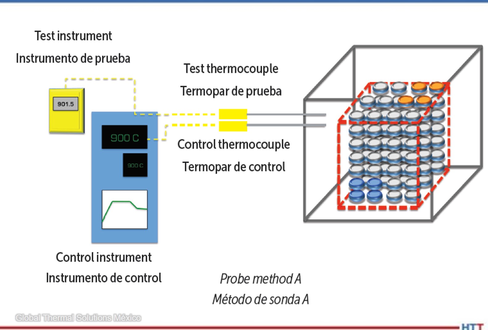
OCThe AIAG CQI-9 (Heat Treat System Assessment) is the most accepted standard in the automotive industry for the validation of heat treatment operations. This article summarizes the evaluation requirements and illustrates the benefits of conducting this test to identify variations in control systems using the probe method A.

Read the English translation of this Technical Tuesday article by Erika Zarazúa, regional purchasing manager at Global Thermal Solutions, in the version below, or read both the Spanish and the English translation of the article where it was originally published: Heat Treat Today's August 2022 Automotive print edition.

"La evaluación CQI-9 (Heat Treat System Assessment) de AIAG es el estándar mas aceptado en la industria automotriz. . . ."


Erika Zarazúa
Regional Purchasing Manager 
Global Thermal Solutions México
Source: Global Thermal Solutions México

1. Application

System Accuracy Tests (SATs) must be performed on all control, monitoring, and recording systems of thermal processing equipment. This does not apply to “high limit” systems, whose sole function is to protect the furnace from overheating.

Contact us with your Reader Feedback!

The test thermocouple used for the SAT must meet the accuracy requirements defined by CQI-9 in table P3.1.3 (±1.1°C or ±2°F maximum error). Similarly, table P3.2.1 of the same section defines the requirements for the field test instrument (±0.6°C or ±1°F maximum error).

SATs conducted by “probe method” should be performed quarterly or after any maintenance that could affect the accuracy of the measurement system such as:

  • Replacement of lead wire
  • Replacement of the control thermocouple
  • Replacement of the control/recording instrument

2. Procedure (Probe Method A)

Probe method A is a comparison between the furnace temperature reading and a corrected test temperature reading.

Table 1. Probe method A
Tabla 1. Método de sonda A

When inserting the test thermocouple, ensure that the tip of the probe is placed as close as possible to the tip of the thermocouple to be tested, and no further than 50mm. Once placed in the test position, it is recommended to allow some time for both systems to reach equilibrium before conducting the test.

If the difference between the furnace temperature reading and corrected reading of the test system exceeds ±10°F (±5°C), then corrective actions must be conducted before processing a product. The most common corrective actions are to replace the control thermocouple, calibrate and adjust the control/recording instrument, or to combine both methods. According to CQI-9, these actions must be documented.

3. Records

CQI-9 revision 4 specifies that the SAT must be documented, and the records must include, at a minimum, the following information:

a. Furnace thermocouple identification
b. Test thermocouple identification
c. Identification of the test instrument
d. Date and time of the test
e. Setpoint value
f. Reading observed in the control system
g. Observed reading on test system
h. Thermocouple and test instrument correction factors
i. Test system corrected reading
j. Difference calculated from the SAT
k. Name and signature of the technician performing the test
l. Company performing the test (if external)
m. ISO/IEC 17025 accreditation of the company (if external)
n. Approval of the person responsible for heat treatment

4. Conclusion

The pyrometry section of CQI-9 lists the requirements and procedures for conducting system accuracy tests (Section P3.3). Within CQI-9, there are two important requirements heat treaters must be aware of. First, the furnace temperature measurement system must not deviate more than ±10°F (±5°C) from the test system. If this is the case, the equipment must not be used for thermal processing and corrective actions must be taken. Second, the SAT report must contain each time this test is conducted. With probe method A, variations in controls systems are easily identifiable.


References

[1] CQI-9 Special Process: Heat Treat System Assessment, 4th Edition. Automotive Industry Action Group, 2020.

[2] International Organization for Standardization; ISO/IEC 17025, General requirements for the competence of testing and calibration laboratories, 3rd Edition. International Organization for Standardization, 2017.

(Photo source: Global Thermal Solutions)


About the Author: Erika Zarazúa, a 40 Under 40 Class of 2021 member, is a metallurgical engineer with over 18 years of experience in heat treatment operations and temperature measurement and has worked in multiple engineering, quality, and project roles in the automotive and aerospace industries. Erika currently holds the position of regional purchasing manager at Global Thermal Solutions.

Contact Erika: erika@globalthermalsolutions.com


Find heat treating products and services when you search on Heat Treat Buyers Guide.com


Guide To Conducting SATs According to CQI-9 4th Edition Read More »

Guía para conducir pruebas System Accuracy Tests conforme a CQI-9 4ta. Edición

OCThe AIAG CQI-9 (Heat Treat System Assessment) is the most accepted standard in the automotive industry for the validation of heat treatment operations. This article summarizes the evaluation requirements and illustrates the benefits of conducting this test to identify variations in control systems using the probe method A.

Read the Spanish translation of this article by Erika Zarazúa, gerente regional de compras de Global Thermal Solutions México, in the version below, or read both the Spanish and the English translation of the article where it was originally published: Heat Treat Today's August 2022 Automotive print edition.

La evaluación CQI-9 (Heat Treat System Assessment) de AIAG es el estándar mas aceptado en la industria automotriz para la validación de operaciones de tratamiento térmico y, entre muchas cosas, describe los requisitos generales y el procedimiento para conducir las pruebas SAT (System Accuracy Test) a los sistemas medición de temperatura de los equipos de procesamiento térmico. Este artículo sintetiza los requerimientos de la evaluación e ilustra los beneficios de conducir esta prueba para identificar variaciones en los sistemas de control mediante el método de sonda “A”.


Erika Zarazúa
Gerente Regional de Compras 
Global Thermal Solutions México
Source: Global Thermal Solutions México

1. Aplicación

Las pruebas SAT deben realizarse a todos los sistemas de control, monitoreo y registro de los equipos de procesamiento térmico. Esto no aplica para los sistemas de ‘alto-límite” cuya única función es la de proteger al horno de un sobre calentamiento.

Contact us with your Reader Feedback!

El termopar de prueba empleado para la prueba SAT debe cumplir con los requisitos de precisión que define CQI-9 en la tabla P3.1.3 de la sección de Pirometría (±1.1°C o ±2°F máximo de error). De igual manera, la tabla P3.2.1 de la misma sección define los requisitos para el instrumento de prueba - field test instrument (±0.6°C o ±1°F máximo de error).

Las pruebas SAT por el método de sonda deben realizarse trimestralmente o después de algún mantenimiento que pudiera afectar la precisión del sistema de medición como:

  • Reemplazo del cable de extensión
  • Reemplazo del termopar de control
  • Reemplazo del instrumento de control/registro

2. Procedimiento (Método de sonda A)

El método de sonda A es una comparación entre la lectura del sistema de medición del horno y un sistema de medición de prueba corregido:

Table 1. Probe method A
Tabla 1. Método de sonda A

Al insertar el termopar de prueba, se debe asegurar que la punta se coloque lo mas cerca de la punta del termopar a ser probado, y no mas lejos de 50mm. Una vez colocado en la posición de prueba, se recomienda permitir cierto tiempo para que ambos sistemas alcancen un equilibrio antes de conducir la prueba.

Si la diferencia entre el sistema de medición del horno y sistema de prueba corregido excede de ±5°C (±10°F) entonces se deben conducir acciones correctivas antes de procesar producto. Las acciones correctivas mas comunes consisten en reemplazar el termopar de control, calibrar y ajustar el instrumento de control/registro o una combinación de ambas. De acuerdo a CQI-9, estas acciones deben ser documentadas.

3. Registros

CQI-9 revisión 4 especifica que la prueba SAT debe documentarse y los registros deben incluir como mínimo la siguiente información

a. Identificación del termopar del horno
b. Identificación del termopar de prueba
c. Identificación del instrumento de prueba
d. Fecha y hora de la prueba
e. Valor del setpoint
f. Lectura observada en el sistema de control
g. Lectura observada en el sistema de prueba
h. Factores de corrección del termopar e instrumento de prueba
i. Lectura corregida del sistema de prueba
j. Diferencia calculada del SAT
k. Nombre y firma del técnico que realiza la prueba
l. Compañía que realiza la prueba (si es externa)
m. Acreditación en ISO/IEC 17025 de la compañía (si es externa)
n. Aprobación del responsable de tratamiento térmico

4. En resumen

La sección de Pirometría de CQI-9 revisión 4 indica los requerimientos y el procedimiento para la realización de la prueba SAT (Sección P3.3).

El sistema de medición de temperatura del horno no debe presentar una desviación mayor a los ±5°C (±10°F) respecto al sistema de prueba. Si este fuera el caso, el equipo no debe usarse para procesamiento térmico y deben aplicarse acciones correctivas.

CQI-9 especifi ca la información que debe contener el informe de SAT cada vez que se conduce esta prueba.


Referencias

[1] Automotive Industry Action Group; CQI-9 Special Process: Heat Treat System Assessment, 4rd Edition, June 2020.

[2] International Organization for Standardization; ISO/IEC 17025, General requirements for the competence of testing and calibration laboratories. 3rd Edition, 2017.

(Fuente de la foto: Global Thermal Solutions)

Sobre el autor: Erika Zarazúa es Ingeniera Química Metalúrgica por parte de la Universidad Autónoma de Querétaro. Con más de 18 años de experiencia en operaciones de tratamiento térmico y medición de temperatura, ha trabajado en múltiples roles de ingeniería, calidad y proyectos en las industrias automotriz y aeroespacial. Actualmente ocupa el cargo de Gerente Regional de Compras de Global Thermal Solutions.

Contacto Erika: erika@globalthermalsolutions.com


Find heat treating products and services when you search on Heat Treat Buyers Guide.com


Guía para conducir pruebas System Accuracy Tests conforme a CQI-9 4ta. Edición Read More »

Don’t Be Unique! 10 Temperature Uniformity Tips

OCWe’ve assembled some of the top 101 Heat Treat Tips that heat treating professionals submitted over the last three years into todays original content. If you want more, search for “101 heat treat tips” on the website! Today’s tips are all things temperature: thermocouples, how to keep temperatures in check, TUS, and more.

By the way, Heat Treat Today introduced Heat Treat Resources this year; this is a feature you can use when you’re at the plant or on the road. Check out the digital edition of the September Tradeshow magazine to check it out yourself!


Temperature Monitoring When the Pressure is On!

Increasing in popularity in the carburizing market is the use of batch or semi-continuous batch low pressure carburizing furnaces. Following the diffusion, the product is transferred to a high-pressure gas quench chamber where the product is rapidly gas cooled using typically N2 or Helium at up to 20 bar pressure.

In such processes, the technical challenge for thru-process temperature monitoring is twofold. The thermal barrier must be capable of protecting against not only heat during the carburizing, but also very rapid pressure and temperature changes inflicted by the gas quench. From a data collection perspective, to efficiently perform temperature uniformity surveys at different temperature levels in the furnace it is important that temperature readings can be reviewed live from the process but without need for trailing thermocouples.

During the gas quench, the barrier needs to be protected from Nitrogen N2(g) or Helium He(g) gas pressures up to 20 bar. Such pressures on the flat top of the barrier would create excessive stress to the metal work and internal insulation / logger. To protect the barrier therefore a separate gas quench deflector is used. The tapered top plate deflects the gas away from the barrier. The unique Phoenix design means the plate is supported on either four or six support legs. As it is not in contact with the barrier no force is applied directly to the barrier and the force is shared between the support legs. The quench shield in addition to protecting against pressure, also acts as an additional reflective IR shield reducing the rate if IR absorption by the barrier in the vacuum heating chamber.

(PhoenixTM)


3 Tips to Meet Temperature Uniformity Surveys

  1. Adjust the burners with some excess air to improve convection.
  2. Make sure that the low fire adjustment is as small as possible. Since low fire will provide very little energy, it will make the furnace pulse more frequently and this will improve heat transfer by convection and radiation.
  3. Increase internal pressure. This will “push” heat to dead zones allowing you to increase your coldest thermocouples (typically near the floor and in the corners of the furnace).

(Nutec Bickley)


Ways to Increase Temperature Uniformity in Heat Treat Furnaces

  1. A (sometimes) simple way to increase uniformity in a furnace is to add a circulation fan. Circulation fans can be a quick way to add an additional 5°F tighter uniformity on a batch furnace application.
  2. Be sure that the furnace is tuned optimally to reduce/eliminate any overshoot and oscillation around setpoint.
  3. Eliminate any thermal lag by making sure that the control thermocouple and TUS thermocouples have similar sensitivity. If not, the control thermocouples can fall behind and cause the TUS thermocouples to overshoot and fail.

(L & L Special Furnace Co., Inc.)


Pack Your Thermocouples

When a thermocouple is used with an open-ended protection tube, pack rope or fiber between the thermocouple and the protection tube to prevent cold air infiltration from influencing the reading.

(Super Systems, Inc.)


A Good Fit

If a thermocouple fits loosely in a protection tube, avoid errors by ensuring that the tip maintains good contact with the tube.

(Super Systems, Inc.)


Introducing Your Common Thermocouple Types

What are the common thermocouple types?

Thermocouple material is available in types K, J, E, N, T, R, S, and B. These thermocouple types can be separated into two categories: Base and Noble Metals.

Types K, J, E, N, and T are Base Metals. They are made from common materials such as Nickel, Copper, Iron, Chromium, and Aluminum. Each base metal thermocouple has preferred usage conditions.

Types S, R, and B thermocouples are Noble Metals because they are made of one or more of the noble metals, such as Ruthenium, Rhodium, Palladium, Silver, Osmium, Iridium, Platinum, and Gold. Noble metals resist oxidation and corrosion in moist air. Noble metals are not easily attacked by acids. Some Noble metal thermocouples can be used as high as 3100°F.

(Pelican Wire)


Culprits of a Stable Thermocouple

Factors affecting the stability of a thermocouple:

The EMF output of any thermocouple will change slightly with time in service and at elevated temperatures. The rate and change are influenced by metallurgical and environmental factors. The four factors that can induce EMF drift are: Evaporation, Diffusion, Oxidation, and Contamination.

(Pelican Wire)


Does Length Matter?

Does the length of a thermocouple wire matter?

In a word, “Yes.” There are several factors when considering the maximum length of a thermocouple assembly. Total loop resistance and electrical noise. Total loop resistance should be kept under 100 ohms for any given thermocouple assembly. Remember, the total loop resistance would include any extension wire used to complete the circuit. Motors and power wires can create noise that could affect the EMF output.

(Pelican Wire)


Type N Thermocouple (Nicrosil/Nisil)

Type N Thermocouple (Nicrosil/Nisil): The Type N shares the same accuracy and temperature limits as the Type K. Type N is slightly more expensive and has better repeatability between 572°F to 932°F (300°C to 500°C) compared to type K.

(Pelican Wire)


Know Your Thermocouple Wire Insulations

Know your thermocouple wire insulations. When is Teflon® not Teflon®? Teflon® is a brand name for PTFE or Polytetrafluoroethylene owned by Chemours, a spin-off from Dupont. FEP is Fluorinated Ethylene Propylene. PFA is Perfluoroalkoxy Polymer. All three are part of the Fluoropolymer family but have different properties. Of the three compounds, PTFE has the highest heat resistance, PFA second highest and FEP third. The higher the heat resistance the more expensive the insulation. Keep that in mind when specifying the insulation and only pay for what you need.

(Pelican Wire)


Check out these magazines to see where these tips were first featured:


Don’t Be Unique! 10 Temperature Uniformity Tips Read More »

Heat Treating with Digital Solutions for the 21st Century

OCOn this Technical Tuesday, dive deep into this article to learn Industry 4.0 heat treating solutions to enduring problems. As author and captive heat treater Joseph Mitchell, director of Operations & Technology for The Miller Company, says, "These solutions have the capability to mitigate incessant (and costly) problems in our thermal and metal processing industry." Let's take a closer look at Industry 4.0 solutions to the problem of coil wraps "sticking" during batch annealing.


Joseph Mitchell
Director of Operations & Technology
The Miller Company

As US manufacturing recovers from the ill effects of a seemingly unremitting pandemic and corollary supply chain challenges, the advance of Industry 4.0 and Industrial Internet of Things (IIOT) necessitates manufacturing industries reevaluate their business practices. For maximum profitability, business "as usual" simply will no longer suffice. Jason Ryska, global chief engineer at Ford Motor Company, suggests even production behemoths overlook the obvious:

In many production processes, data analytics provides the agility to keep up with market trends and technology advancements. An exception to this trend is automotive production, a multi-billion-dollar industry that is underutilizing data collection and underestimating the potential improvement that may come from understanding the data being collected.

This quote is from a technical article written by Ryska in which he discusses current state and offers a glimpse of future state that is gained by a manufacturer investigating potential new solutions for old process problems by applying Industry 4.0 technologies.1

Metal industry leaders may ask, to the quote above, could we replace "automotive production" with "heat treating?" I believe there is a strong argument against such an exchange of words; however, in-depth examination at the plant level indicates deficiencies exist for the heat treating industry related to acceptance of IIOT technology and application of data analytics. Where do we observe the shortcomings? Perhaps, as suggested by Ryska, in our day-to-day comfort zone: "over reliance on employee experience and interpretation vs. physical measurements."

This keen insight into the current state of automotive manufacturing can be equally applied to different manufacturing landscapes throughout U.S. industry. Reviewing a familiar heat treating problem will help to illustrate the need for and applicability of digital monitoring and data collection for decision making and future development of advanced analytics like machine learning and AI. These solutions have the capability to mitigate incessant (and costly) problems in our thermal and metal processing industry.

Yellow brass finished width coils; alloy C26800

Heat Treat Industry

In manufacturing, the same problems often occur again and again. In the metals industry, casting and thermal processing, in conjunction with continuing operations, present daily challenges to product quality. Troublesome and costly conundrums – like residual stress, distortion, cracking/poor forming in downstream operations, and poor surface quality/coating adhesion – occur regularly, causing waste, rework, late delivery, and lost profit.

Metallurgists, engineers, and technologists all understand the frustration of untold hours devoted to researching solutions to material processing problems. Some already have well known solutions while others may randomly appear seem, after causing much angst, to disappear (sometimes not as quickly as would be preferred). Regardless of that type of problem, the time, effort, and resources put into finding the solution cannot be redeemed.

The advance of Industry 4.0 and, more specifically, IIOT into modern manufacturing can provide our metal production sector the ultimate tools for unraveling costly and recurring quality issues. We understand this progression will be gradual and very slow.

Nonetheless, implementation of digital technologies is critical for our heat treating/materials processing industry. The fact CQI-9 4th ed. requires all instrumentation and process controls be digital by June 2023 supports the emphasis placed on eliminating analog based instruments and reengineering manufacturing processes for implementation of digital data collection and, thereby, steering heat treaters (automotive suppliers and, hopefully, non-automotive industrial heat treaters) toward eventual adoption of Industry 4.0 technologies.

In this article, we review a specific quandary typically encountered during batch annealing and examine why application of digital monitoring and data collection, and eventual integration of Industry 4.0 technologies, would facilitate understanding and assist in resolving the problem.

The Problem (Define)

A report, written in 1940 by T.J. Daniels, titled "The Prevention of Sticking in Bright Annealing Sheet Steel" is interesting for many reasons, and, for purpose of this article, provides an example of an early 20th century heat treating headache which, unfortunately, is still with us in the present century.2

The report consists of two parts:

Part I - Investigation of Factors Influencing Sticking

  1. Pressure
  2. Annealing temperature
  3. Length of time at temperature

Part II - Prevention of Sticking

  1. Multiple varieties of trial suspensions tested
  2. Temperature, pressure, and time held constant for each test
  3. Trials performed 2x each
  4. Trials performed 3x for promising suspensions

Despite the efforts and subsequent process improvements in heat treating and manufacturing processes as discussed in Daniels' report, we find the following, equally interesting 21st century report, addressing the same subject in Hot and Cold Rolling Processes, Sticking and Scratching Problems After Batch Annealing, Including Coil Compression Stress Effects, by J.J. Bertrandie, L. Bordignon, P.D. Putz, and G. Volger.3

This 2006 report discusses the same sticking phenomenon (coil wraps adhering together after batch annealing) and expands its research into an accompanying quality problem that may occur in conjunction with or subsequent to batch annealing: material scratching. The report documents field trials and laboratory investigations.

The amount of investigative work described in this second report is noteworthy and the results provide data-backed conclusions. However, the problem addressed, potential causes studied, and solutions prescribed did not eliminate the phenomenon of sticking following batch anneal of ferrous and nonferrous coils. Fast-forward fifteen years to 2021 and the sticking phenomenon remains a topic of discussion (and source of grief) for heat treaters across continents.

My experience with a heat treater located in the Midwest, who occasionally encountered coil wraps sticking together during batch anneal of sheet steel, resulted in experiments with anti-sticking agents applied using a spray system, as well as studies for improved control of cooling the furnace charge. The cooling temperature gradient influences contraction of outer wraps which, if pressure is excessive, may result in wrap adhesion (cementation): growth of crystals across material wraps.

Although sporadic, costs were significant when sticking occurred. Unfortunately, the success of our experiments was limited due to time constraints and production requirements (nothing new here). As we know, a hit-or-miss success rate is not good for business; consequently, continuous improvement (CI) must be built into the system. Fortunately, technology is allowing this CI business approach by way of Industry 4.0.

Per CQI-9 rev. 4, analog process monitoring is coming to an end

Descriptive Analytics (Measure)

I first will acknowledge many industrial processing plants operate using, shall we say, not exactly new or sufficiently updated equipment. Also acknowledged is the necessity of skilled and experienced personnel for monitoring and performing critical tasks. Nonetheless, with all else being equal, the fact this quality defect persists suggests industrial heat treaters need new solution for this old and burdensome problem. In short, transformation to digital technologies must occur in the metals processing industry for improved understanding and resolution of regularly occurring problems coming from complex manufacturing/processing systems.

At minimum, for study and resolution of our sticking problem, I recommend a supervisory control and data acquisition system (SCADA). Management should have "eyes" on the process at all times. SCADA allows digital process monitoring (real-time), process alarms (out-of-spec parameters), and automatic control (process adjustment) that will help improve process control at site location or via remote access. Likewise, data acquisition for historical review is critical for answering the question, "what happened and when?"

Digital collection and transfer of data (cloud-based or in-house server) and use of statistical analysis (data analytics) will help a company improve production through the development of predictive maintenance models, building understanding of equipment capability for effective and efficient processing, and defining key process parameters for best quality.

SCADA may be incrementally introduced into a manufacturing system (e.g., a single bell/box annealing furnace) and scaled accordingly. Another strategy is investment in IIOT technology software/apps/system. My experience includes investigation of IIOT as a service with MindSphere. This technology is scalable and can be integrated with legacy equipment for eventual connection with both old and new machines/processes. This is  a more practical  option considering few small-to-midsize heat treaters have cash for an all-at-once approach.

During initial installation stages, be sure to capture key process variables and the need for strategic placement of data gathering sensors based upon best opportunities for process impact like:

  1. furnace atmosphere / time / temperature
  2. material cleanliness / required microstructure / coil tension
  3. strip thickness / strip width / process routing / pre & post processing

Data input from locations other than annealing furnace are of equal concern:

  1. pickle tank temperature / acid concentration
  2. rinse tank temperature / cleanliness / cycle time
  3. surface roughness / temper rolls / anti-sticking oil

As noted earlier, I understand use of equipment that is in disrepair or outdated is a reality for some heat treaters; fortunately, use of SCADA system would provide necessary data to justify purchasing new equipment and/or upgrading old equipment. A data driven proposal presented in unbiased digital format is an advantage for showing upper-management current state-of-affairs and possible return on investment (ROI) if funding is provided and investments are made.


Digital monitoring of process variables: easy access of data for historical review and troubleshooting

Diagnostic Analytics (Analyze)

At this point, we have a SCADA (or similar) system in place, either for a given furnace/machine, work-cell, or eventually for an entire manufacturing/processing system. In our case, the process parameters associated with sticking, and therefore the ones which need to be monitored, include temperature, time, pressure, surface condition, and reactivity.4 The stage for descriptive analytics is set; data is collected/summarized, but no direct decisions/predictions develop from this digital data stream. We learn "what happened” and proceed with the question, "why" did "X" happen? Thereby, we enter the world of diagnostic analytics in the quest for root causes, seeking to understand unusual events: why did no sticking occur when we processed alloy "A" last week, but this week alloy "A" exhibits sticking?

Following our statistical study used in descriptive and diagnostic analysis that was performed using data analysis software, we continue applying statistical methods for our investigation. The objective is discovery and confirmation of relationships and/or trends, which may relate to, or show causes for, sticking (coil wraps adhering together).

Predictive Analytics (Improve)

Rarely in a heat treating/material processing dilemma is the root cause readily disclosed; my experience in heat treating is that "bad" phenomenon often occur and disappear with impunity, leaving root cause analysis a moot point. We breathe a sigh of relief and enjoy the quiet before the next storm.

In the past, this unfortunate scenario likely resulted from one of two things: first, the inability to measure multiple variables simultaneously; and second, if a system is in place identifying and monitoring key variables, then management's inability of correlating (note: correlation may not ≠ causation) effects of multiple process variables. This inability leads to dependency and/or relationships preventing meaningful and/or accurate interpretation of data. At best, this does no more harm than allow the continued ill-effects of current problem, but at worst, it leads to incorrect conclusions, possible worsening of the problem at hand, and new problems.

Here  is where management of forward-thinking companies --  focused on developing optimal manufacturing efficiencies, equipment effectiveness, increased profit, and competitive advantage --differentiate themselves by advocating application of digital technologies. In this case, it means moving toward artificial intelligence (AI); smart machines/machine learning.

Many options related to machine learning software and machine connectiveness are available (e.g., Siemens, GE Digital, Samsara, etc.). Your SCADA system provider is a great place for beginning investigation into predictive/prescriptive software solutions using machine learning tools.

Another example of a systems approach for digital transformation is Smart Prod ACTIVE. Profiled in Foundry Trade Journal last winter, this information and communication technology (ICT) platform, designed for optimizing foundry production, illustrates the growing possibilities for increased competitive advantage and profit growth based upon implementation of digital technologies, such as EnginSoft - smart ProdACTIVE.5

Prescriptive Analytics (Control)

Heat treating consists of many interrelated processes and/or systems. Prescriptive analytics, by way of simulation software/modeling tools, leads to applicable solutions; as Luigi Vanfretti, an associate professor of electrical, computer, and systems engineering at Rensselaer Polytechnic Institute, states, "You need to have a way to understand the interaction of the systems, and, in an integrated way, you need to optimize them together."6

Digital data collection and advanced analytics open the door for data-driven decisions and improved understanding of a process. When we are able to investigate cause-effect relationship(s) and our modeling tools suggest appropriate/optimal adjustment for non-normal process variation, we can achieve standardization of a given heat treating process, possibly even aimed at specific equipment in a manufacturing system.

In other words, the optimization factors of bell furnace "A" may not be optimal for bell furnace "B." The parameters for various aspects of the manufacturing system may need adjustment based on equipment performance/condition or other factors (e.g., coil mass, time at soak temperature, surface roughness (rolls), incoming strip cleanliness, etc.).

In this manner, continuous improvement throughout the manufacturing system becomes a part of our day-to-day business.

Chart recording; still valid, but not user friendly for data retrieval and statistical analysis

Digital Integration/Transformation

We examined a 21st century approach for resolving a 20th century problem: coil wraps sticking together post-anneal. This material processing phenomenon typically encountered when batch annealing ferrous or nonferrous materials may result from many interrelated process variables; that is, one or more sources of non-normal variation within a thermal processing system and/or manufacturing process.

The heat treating system, as well as the manufacturing system which is comprised of numerous material processes both upstream and downstream, requires continuous monitoring. As supported by CQI-9 (4th ed.), digital instrumentation is deemed necessary (for automotive suppliers) for surveillance and documentation of thermal processing parameters. Acquisition of digital data (e.g., SCADA) facilitates advanced analytics for predicting process outcomes and thereby prescribing optimal solutions which lead to process improvements.

Thus, application of digital monitoring/data collection, advanced analytics, and integration of Industry 4.0 technologies will enhance understanding, provide heretofore unknown process correlations/relationships, and thereby lead to problem mitigation.

As we close this article, some may ask, is digital transformation essential in our heat treating industry? Is IIOT and the all-encompassing Industry 4.0 a necessity for industrial heat treaters and others involved in material processing?

Perhaps a well-worn quote from W. Edwards Deming provides our answer: "It is not necessary to change. Survival is not mandatory."

About the Author: Joseph Mitchell is director of Operations & Technology for The Miller Company, a service slitting center which supplies bronze and specialty copper alloy precision metal strip. With a BS in Industrial Management and MBA from Lawrence Technological University, his interests include metallurgy and practical application of Industry 4.0 concepts/digital technologies for developing business strategy that provide optimal use of assets, energy, and process controls within the metals and automotive industry.


References

1 J. Ryska, Industry 4.0 Meets the Stamping Line - Ford Motor Company's stamping division looks to leap into Industry 4.0 the same way Henry Ford led the transformation from Industry 1.0 to 2.0, Advanced Materials and Processes, Feb/Mar 2020, Vol 178, NO 2, p 25-28.

2 T. Daniels, "The Prevention of Sticking in Bright Annealing Sheet Steel,” Thesis; submitted for degree requirements, MS Chemical Engineering, Georgia School of Technology.

3 J.J. Bertrandie, L. Bordignon, P.D. Putz, G. Volger, Hot and Cold Rolling Processes, Sticking and Scratching Problems after Batch Annealing, including Coil Compression Stress Effects. Directorate-General Research, European Commission, Technical Steel Research, EUR 22059 EN, 2006, Sticking and scratching problems after batch annealing, including coil compression stress effects - Publications Office of the EU (europa.eu).

4 J.J. Bertrandie, L. Bordignon, P.D. Putz, G. Volger., p 21.

5 Foundry Trade Journal, Die Casting World, Vol. 194, No. 3771, Jan/Feb 2020, p 22.

6 Luigi Vanfretti, Modeling Electric Aircraft, Rensselaer Research, RPI, 2019 Research Report; Modeling Electric Aircraft | Office for Research (rpi.edu)


Additional resources mentioned in this article

EnginSoft - smart ProdACTIVE

MindSphere

Heat Treating with Digital Solutions for the 21st Century Read More »