Exploring Thermal Sensors in Hydrogen Atmosphere for Turbines, Part 1 of 2

Direct thermal measurement of temperatures within a turbine is limited due to many factors. Some thermal sensing systems are not able to measure the lower end of the spectrum, while other systems are not able to measure the higher end. In this article, learn how Nanmac and Rhenium Alloys, Inc. worked together to discover a thermal sensing system in hydrogen atmospheres that solved these issues and more.
Today's Technical Tuesday was written by Herbert Dwyer, chief technical officer of Nanmac and president of Herb Dwyer & Associates, LLC., and Todd Leonhardt, metallurgist and director of Research & Development at Rhenium Alloys, Inc. This article was originally published in Heat Treat Today’s December 2021 Medical & Energy print edition.
Introduction

Metallurgist and Director of Research & Development
Rhenium Alloys, Inc.

CTO, Nanmac
President, Herb Dwyer & Associates
Direct thermal measurement of temperatures within the turbine (both fixed and aviation) and on the test stand, has been limited to 2642°F (1450°C). This uses a precious metal thermocouple composed of platinum (Pt) and rhodium (Rh) which are very expensive and have limited life above 3182°F (1750°C).
The conditions within the turbine also limit the choice of direct measurement systems due to the combustion by-products, wind speeds, pressures, shear forces, vibration, and thermal shock.
The recent focus on “green energy” gases that are more friendly to the atmosphere and offer excellent energy density per volume of gas points to a gas that has been around for many years — hydrogen. However, the use of hydrogen as a combustion gas within the turbine can be challenging as well. Molecular hydrogen is generally smaller than molecular oxygen. The by-product of the combustion of hydrogen and oxygen forms water. Water vapor is more climate friendly than carbon monoxide, carbon dioxide, or other forms of carbon found in turbines using standard jet fuels, natural gas, or combinations. Another challenge is the wide variety of temperatures to be measured at various points within the turbine, from inlet air to combustion to outlet air, the range can be from -22°F (-30°C) or lower to a predicted high of 4172°F (2300°C). No one type of thermal measuring system exists today that covers this total range. With this as a baseline, Nanmac and Rhenium Alloys, Inc. worked together to explore various combinations of material systems that could operate at the lower temperatures, plus reaching the upper temperatures of 4172°F (2300°C).
The system that could cover this range was the Type C thermocouple with a 5% tungsten and 26% rhenium wire composition. One key part of the system is the insulator which separates the two legs of the thermocouple, the second key part is the refractory sheath like tantalum or molybdenum. The range of temperature covered by this combination was from about 662°F (350°C) to 4172°F (2300°C). The actual testing temperature was performed from 1292°F (700°C) to 3992°F (2200°C).
Application and Testing Objectives:
- Fixed and aviation turbines (includes direct mount and test stands)
- Test temperatures above the 2642°F (1450°C) range
- 100% hydrogen atmospheres
- Thermal shock issues
- Life issues at elevated temperatures and stress
- High shear stress caused by air flow
- Low and high frequency vibrations
- Mounting options to accommodate space issues
- Atmospheric corrosion caused by particulates in combustion gases
- Cold junction transition location
- Mounting depth
Objectives, Equipment, Assembly, and Test Times
Of concern, as atmospheres approach the ultra-high temperatures (UHT) region above 2642°F (1450°C), there are materials interactions between the components of the thermocouple (sheath, insulators, and thermocouple wires) and the furnace environment (representing the combustion section of the turbine) at elevated temperatures. Individually, the materials have high melting points, but combining these materials within the thermocouple system can cause low melting point eutectic to form a reaction between materials to occur. These material interactions can cause the thermocouple to fail prematurely in service at unexpectedly lower temperatures than predicted.
During Nanmac’s material compatibility testing, interactions between the sheath, insulators, and Type C thermocouple wire occurred. The weak link in the thermocouple system is the high temperature insulators of hafnia, alumina, and boron nitride. As the temperature approached the 3812°F (2100°C) test temperature, the insulators decomposed. Some of the observed failures appeared to be due to the hydrogen gas penetrating the end closure welds or even through the sheath walls; some of the insulators failed at these temperatures at much lower levels than expected. Some failure modes were caused by the insulator melting and attacking the thermocouple wires leading to fractures of the junction welds and the individual thermocouple wires.
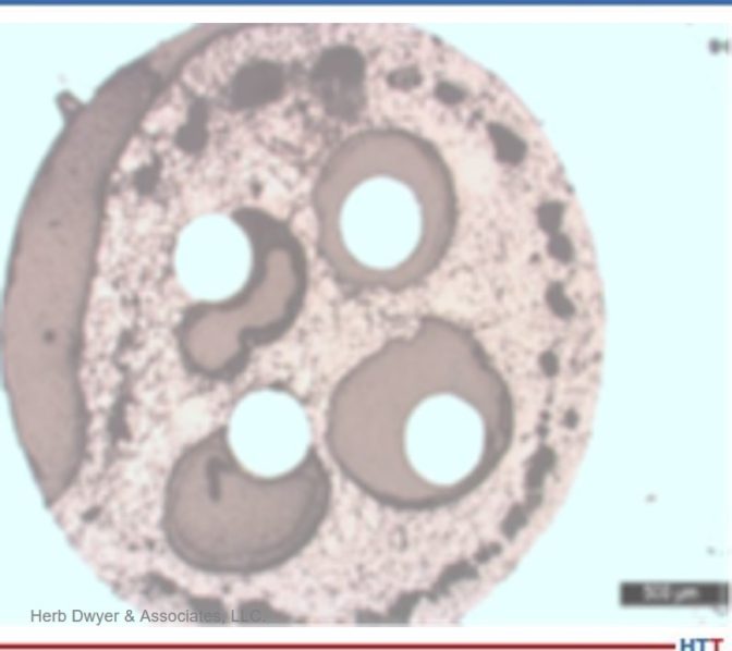
Photo Credit: Herb Dwyer & Associates, LLC
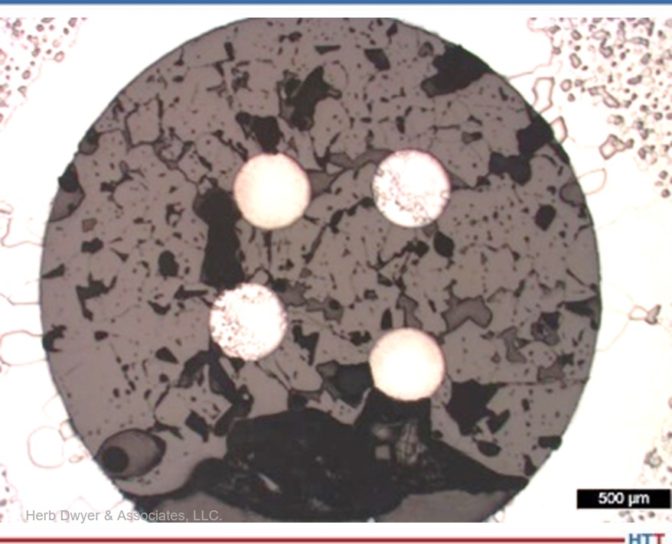
Photo Credit: Herb Dwyer & Associates, LLC
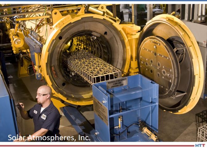
Nanmac and Rhenium Alloys, Inc. used hydrogen cover gas because of access to a furnace which used that atmosphere. The use of hydrogen as a future combustion gas gave insight into how these material systems would operate in that harsh environment. The furnace also gave insight into the thermal shock issues from quenching the furnace with hydrogen gas for rapid cooling which allowed for a quick turnaround in testing. Additionally, the processes helped evaluate the possible impact of 100% hydrogen atmosphere on the insulator’s materials, wire junction welds, and sheath end closure weld. The furnace used for compatibility testing used a calibrated control system with a reference thermocouple and a calibrated optical pyrometer.
The test assemblies for compatibility testing were smaller lengths of typical thermocouple systems composed of the 0.050” walled molybdenum sheath. The insulators tested included: hafnia (HfO2); 99% alumina (Al2O3), and boron nitride (BN insulator and Type C 24 AWG [0.020]) thermocouple wire assembly, which was back filled with argon gas to prevent oxidation of the components. Test durations were one hour, two hours, and six hours, at elevated temperature and a complete post-mortem evaluation was performed on all test articles to evaluate compatibility of the thermocouple components at UHT.
Discussion:
The ASTM E20 Committee is exploring the possible increase in calibration temperatures from the existing 2642°F (1450°C) to 3182°F (1750°C) or higher. While it appears the individual materials can achieve these and even higher temperatures, tests indicate that this is not the case for all the combined thermocouple components.
Discussion of some of the material issues includes:
1. As atmospheres reach 3182°F (1750°C) and up to 4172°F (2300°C), materials are limited to refractory materials like:
- Molybdenum, tantalum, platinum, and other alloys of these materials.
- Ceramics like 99% alumina, zirconia, hafnia, boron nitride, silicon nitride (SiC), and others were tested.
- Wire materials are limited to some alloys of tungsten (W) and rhenium (Re).
2. Combining these materials also lowers the system’s overall temperature. For example, the boron nitride, on its own, can reach temperatures up to 5252°F (2900°C), but when combined with the Type C wire and molybdenum sheath, it can only operate reliably to 3632°F (2000°C). Figures 1 and 2 are examples of failures of ceramic insulator exposed to high temperature service conditions.
NOTE: During lab analysis, at the various temperatures, it was observed that decomposition and significant degrading of the insulators had occurred. The exposure to the UHT not only attacked the ceramic insulators but also attacked the Type C wire and its sheath. Part two of this article will show some of the pictures of this attack and discuss some of the approaches to address this material issue at these UHTs, above the threshold of 3182°F (1750°C).
3. Cost now becomes a significant driver. Some of these materials, including alloys of platinum and rhodium can cost upwards of $2,000 or more per inch, are very hard to machine and form, and can contain hidden cracks and voids that under these extreme temperatures lead to reduced mechanical life.
4. The operating atmospheres have a significant impact on the alloys used, and high carbon loads from unburned fuel can also impact these refractory materials, for example:
- Oxygen attacks molybdenum, tungsten, and even tantalum, although to a lesser extent than the attack on molybdenum.
- Hydrogen’s small molecules can attack the insulator by penetrating the welds; the insulators exposed to this reducing gas oxidize, melt, and shrink causing potential grounding, secondary junction(s), and further mechanical failure.
- Nitrogen becomes a significant factor when used above 1832°F (1000°C).
5. The operating environment is not friendly to the following:
- The need to directly insert into the combustion gas flow chambers exposes the tip to very concentrated thermal and mechanical forces.
- Space restrictions limit the wall thickness and lengths (to resist H2 penetration and handle the extreme heat, thicker walls and an OD of ¼ inch or higher are required).
- A turbulent air flow at speeds up to 400 mph.
- Air pressures to 500 psi or higher.
6. The shorter the thermocouple (TC) length, additional thermal transfer issues are exacerbated. For example, four inch or shorter lengths can adversely impact any brazed joints from the TC to extension wire [(the temperature in this area where the tip may be at 3632°F (2000°C)], can be 1832°F (1000°C) or higher. Braze joints fail at much lower temperatures.
- The transition at this point may also have insulation issues since it may be difficult to control the addition of an acceptable insulator in the transition area. The potential of secondary junctions is quite high (any significant mechanical movement (expansion and contraction) can cause high stress and weak insulators.
- A technique using swaging has been somewhat successful but requires materials that can be swaged, limiting options to very expensive alternatives today. Some mineral insulated (MI) cables may be acceptable but need more testing.
- The cold reference junction may be unacceptably close to the high temperature (1832°F or 1000°C), thus requiring a relocation further away from this point, requiring possibly a unique analog to digital converter (A/D) like those used in cars. This has not yet been fully developed at this point.
- Nanmac is working on a method to carry the TC wire further into the test stand or turbine. This will address the transition issue, enable the use of existing A/Ds, and offer potential integration into the turbine engine itself.
- By using this method (see d, above) on the test stand, it is possible to economically investigate this method, maintain safe operations, and make it useable once the system issues are resolved at the test stand.
The Type C was chosen for this temperature requirement (4172°F or 2300°C)
- Other than the Type D or A (both of which are in very limited supply and are basically of the same alloy construction), the Type C is well known and characterized, can operate up to 4172°F (2300°C), and has some significant history of use in this temperature realm [the tungsten (W)/Rhenium (Re) alloys are used regularly in high temperature metallurgical furnaces and even within the turbines].
- Type C is recognized by ASTM and NIST, its accuracy is 1%, and by comparison calibration Type C has been shown to be capable to about 0.5%, not the 0.25% of the Type S or R, but at a cost of 75% or less and its life, at elevated temperatures, is good and predictable.
- Type C has existing MI cable matching extension wire.
- Type C has existing A/D systems; thus, it is easier to integrate.
- Type C has existing connectors, color coded wire, and terminal connections.
Can other ceramics reach 4000°F (2204° C)? Can these ultra-high temperature systems be built commercially? To find out the answers to these questions, don’t miss the second part of this article in March’s (2022) Aerospace Heat Treating magazine and learn about the results, conclusions, and next steps.
About the Authors:
Herbert Dwyer is the CTO of Nanmac, and president of Herb Dwyer & Associates, LLC. Herb specializes in international business development, electromechanical manufacturing, heat treating furnace optimization, and thermal measurements up to 4172 °F. Herb has over 50 years of experience in the field of thermal and pressure sensors for the aerospace industry.
Contact Herb at herbdwyer1@gmail.com
Todd Leonhardt, a metallurgist and director of R&D at Rhenium Alloys, Inc., possesses an in-depth knowledge of high temperature refractory metal and is an expert in rhenium. As a 38-year veteran of industrial and government research in the areas of material characterization and processing refractory metals, Todd has shared his knowledge in over 25 publications including NASA technical memorandum, peer review journal articles, and conference proceedings.
Contact Todd at Todd.Leonhardt@rhenium.com
Exploring Thermal Sensors in Hydrogen Atmosphere for Turbines, Part 1 of 2 Read More »


