QUENCHING TECHNICAL CONTENT

Métodos para la medición de la austenita retenida

La mayoría de quienes aplican el tratamiento térmico reconocen la importancia de medir la austenita retenida (RA, por sus siglas en inglés); no obstante, muchos optan por no realizar estas mediciones por razones de tiempo y/o de los costos asociados. Este artículo explica los motivos por los cuales se deben practicar las mediciones RA, los factores a favor y en contra de las tecnologías de medición tradicionales y los beneficios de realizar la medición en la planta misma, utilizando tecnologías más avanzadas.

This informative piece was first released in Heat Treat Today’s March 2025 Aerospace Heat Treating print edition. To read the article in English, click here.


La importancia del porcentaje de austenita retenida

Antes de entrar a examinar algunas metodologías de medición, es necesario entender lo básico en relación a la austenita retenida, al igual que la importancia que reviste el porcentaje de la misma (%RA).

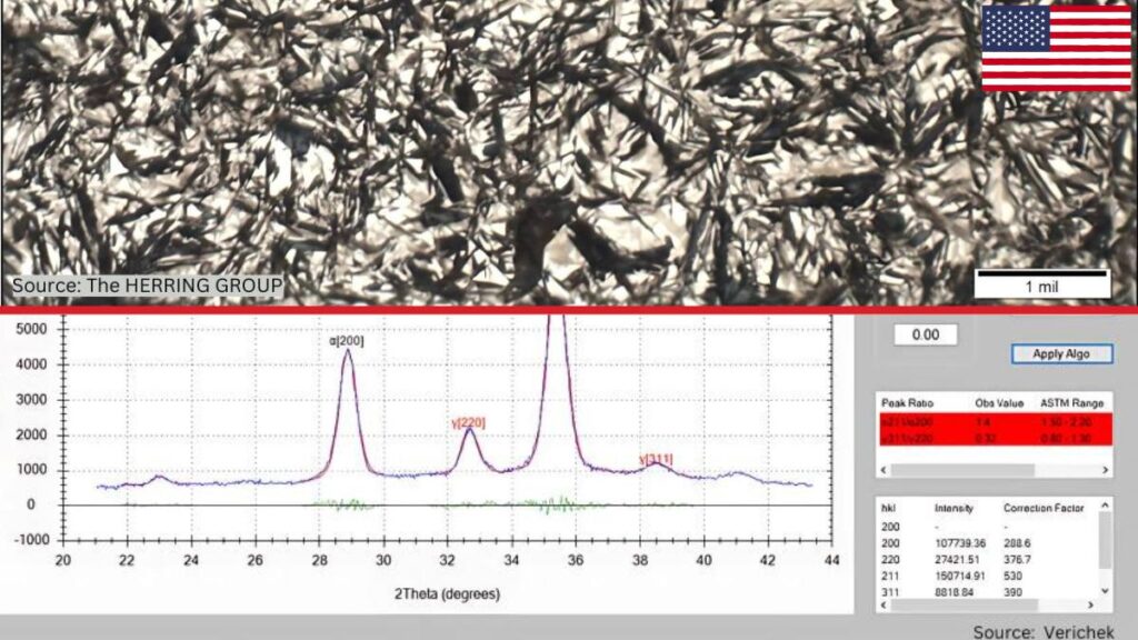
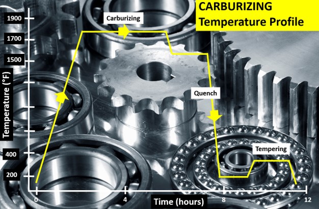
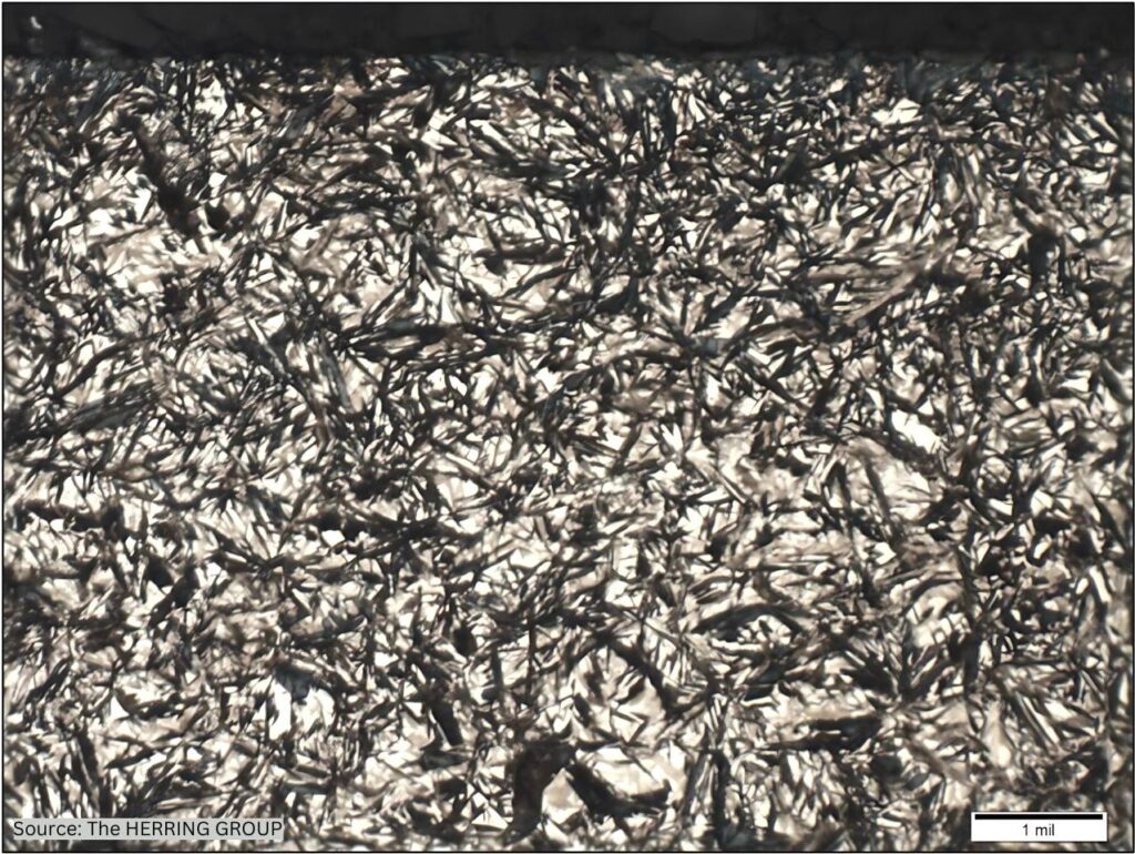
Austenita retenida (RA) es el nombre que se le da a la austenita que durante el proceso de templado no se transforma en martensita. En términos sencillos, la austenita retenida (figura 1) ocurre cuando el acero se ha templado sin llegar de manera contundente a la temperatura de acabado de la martensita (Mf); es decir, la temperatura ha estado por encima de lo requerido para permitir la formación de martensita al 100%. Debido a que la Mf está por debajo de la temperatura ambiente en la mayoría de las aleaciones que contienen más del 0.30% de carbón, se pueden presentar cantidades significativas de austenita retenida en la martensita a temperatura ambiente. (Herring, Atmosphere Heat Treatment).

Al tratarse del %RA, con frecuencia existe un equilibrio muy sensible entre sus efectos benéficos (el aumento en la durabilidad de ciertos componentes manufacturados) y sus atributos negativos (la creación de piezas susceptibles de fracturas y averías). Por tal motivo es de crítica importancia que los tratadores térmicos logren el %RA óptimo para la aplicación deseada.

Por ejemplo, en las industrias de la aeronáutica y la astronáutica, con frecuencia se especifica que los niveles de RA sean inferiores al 8%, y para piezas como los cojinetes y los actuadores lineales, se requiere un RA por debajo del 3%, lo más cercano posible a cero. No obstante, en otras aplicaciones, como por ejemplo los engranajes grandes para generadores de energía, energía eólica y plataformas de rendimiento, se ha identificado que un RA en el rango del 15-30% reviste mayores beneficios. (Errichello et al., “Investigations of Bearing Failures”). De igual manera, un alto % RA es una ventaja en el caso de cojinetes que vayan a entrar en contacto con lubricantes contaminados.

Figura 1. Microestructura en la superficie de la trayectoria de un cojinete de rodamiento 12CrNi3 (o SAE/AISI 9310) compuesto por martensita templada en la que se evidencia austenita retenida (áreas blancas)

Marco DeGasperi, gerente técnico de Verichek, se pronunció al respecto señalando que el %RA es de crítica importancia para los inyectores de combustible, para piezas pequeñas en aplicaciones médicas y para aplicaciones de alto nivel y alto volumen tales como las placas de desgaste en la industria minera. Lo resumió afirmando: –Cuando tu ejercicio se trate de someter a presión y movimiento cualquier dispositivo de calibración fina…si utilizas la palabra “precisión” para darte a conocer, vas a querer hacerte a una [herramienta de medición del %RA].

Las mismas características que le dan a la austenita retenida muchas de sus propiedades particulares, son a la vez las respons ables de significativos problemas de funcionamiento. Sabemos que la austenita es la fase normal del acero a altas temperaturas, mas no a temperatura ambiente. Debido a que la austenita retenida existe por fuera del rango normal de su temperatura, es metaestable, lo que quiere decir que, cuando entre en funcionamiento, los factores como la temperatura, el estrés, y aún el tiempo, harán que se transforme en martensita no revenida. Es más, junto con dicha transformación se dará un cambio en el volumen (aumentará) generando un alto grado de estrés interno en el componente y provocando muchas veces la formación de grietas lo que podrá llevar a que las piezas fallen en el campo.

El % RA también es importante, no solo por el impacto sobre la estabilidad dimensional, sino además por las propiedades mecánicas tales como el límite elástico, la resistencia a la fatiga, la tenacidad, y la manejabilidad. (Herring, Atmosphere Heat Treatment). A manera de ejemplo, DeGasperi identifica en la industria automotriz las consecuencias de un %RA demasiado alto o demasiado bajo: –Hablemos de las piezas en una transmisión o en una caja de transferencia; aquí es donde se dan los casos en los que se empiezan a romper los cojinetes, o terminas viéndote en la obligación del retiro masivo del producto del mercado. Y por lo general toda la cadena de suministro identifica al anterior como el culpable cuando ninguno en toda la cadena se ha tomado la molestia de probar las piezas por sí mismo.

Por el contrario, en algunos casos, la RA diseminada en pequeñas cantidades aporta para que el material resista la propagación de fracturas por fatiga y disminuye el estrés por fatiga en el contacto de rodamiento, así que lograr el correcto equilibrio en la cantidad de RA es importante en muchas aplicaciones. Además, el % justo de RA es esencial para el control de calidad, al igual que para evitar problemas de seguridad y retiros masivos del mercado. El debido control y la medición precisa del % RA en las aleaciones de acero es un punto crítico para garantizar la calidad y la seguridad de los componentes terminados, salvaguardando así la reputación y el margen de ganancia tanto de los tratadores térmicos como de los fabricantes.

Métodos de medición de RA

El medir con precisión la RA es de vital importancia para establecer si existe el balance correcto entre la austenita retenida y la martensita en determinado componente. Los tratadores térmicos tienen a su disposición varias metodologías para esta medición, cada una con sus respectivas ventajas y desventajas. Para el tratador térmico entender la importancia de medir el % RA representa tan solo una parte de la batalla ganada, mientras que la otra parte se gana cuando se logra identificar un método de medición que sea rápido, preciso y rentable.

La difracción de rayos-X: el mejor y más preciso de los métodos

Figura 2a. Una unidad de sobremesa ArexD de GNR

La difracción de rayos-X, utilizada para identificar y cuantificar las fases en un material, se considera el método más preciso de medición de RA en acero ya que logra establecer los niveles de RA hasta el rango aproximado de 0.5-1% (GNR, “AreX Diffractometer,” 3). En la difracción de rayos-X, las diferentes fases cristalinas demuestran diferentes patrones de difracción, lo que permite que sean identificadas y medidas. Además del análisis de fases, la difracción de rayos-X se puede utilizar para analizar car acterísticas microestructurales tales como la textura, el esfuerzo residual y el tamaño del grano.

Hoy en día, la difracción de rayos-X es una solución segura y no-destructiva que permite valorar una región mucho más amplia que la de varios de los otros métodos disponibles, sin necesidad de gran preparación ni análisis de la muestra, haciendo de ésta una solución más eficiente y efectiva. Es la tecnología más opcionada para una empresa que requiera valorar la RA con un resultado esperado inferior al 10%,

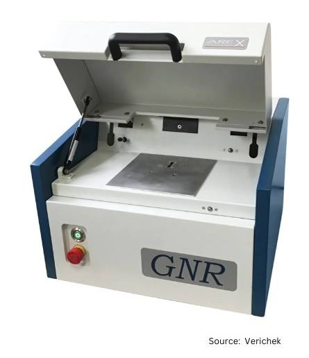
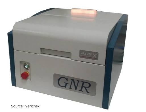
La actual generación de difractómetros de rayos-X ostenta un diseño de sobremesa con un peso aproximado de 25 libras. Existen modelos con costos inferiores a los USD $100.000, lo que los hace rentables frente al costo de un difractómetro tradicional (USD $200.000) que tenía además la desventaja de presentar dificultades cuando la muestra tuviera fases y reflexiones adicionales, ya fuera por el tamaño del grano, por los carburos o por las texturas que pudieran provocar disturbios y variaciones en la medición. La nueva generación de equipos de rayos-X logra superar estos obstáculos utilizando múltiples picos de difracción para minimizar los efectos de la orientación preferida y detectar la interferencia de los carburos.

Figura 2b. Una unidad de sobremesa ArexD de GNR

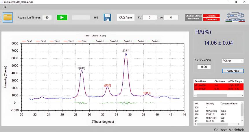
Las máquinas modernas de difracción de rayos-X tienen la capacidad de recoger hasta siete picos de difracción (tres para la fase ferrítica/martensítica y cuatro para la fase austenítica) para luego establecer la concentración de porcentaje por volumen de RA en la muestra al comparar las intensidades de los picos y analizar las relaciones entre éstos de acuerdo con el ASTM E975-22 (práctica estándar para la determinación por rayos-X de austenita retenida en acero con orientación cristalográfica cercana a la aleatoria).

No es complicado usar los equipos modernos de difracción de rayos-X. En menos de tres minutos se logra la medición con tan solo ubicar la muestra en la máquina y oprimir el botón de inicio. Estos difractómetros realizan mediciones en muestras de diferentes tamaños y se valen de software intuitivo, dando lugar a que cualquier técnico, tenga o no experiencia previa en metalurgia o difracción, efectúe la medición de manera rápida, precisa y eficiente.

La microscopía óptica: un método a prueba del tiempo

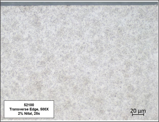
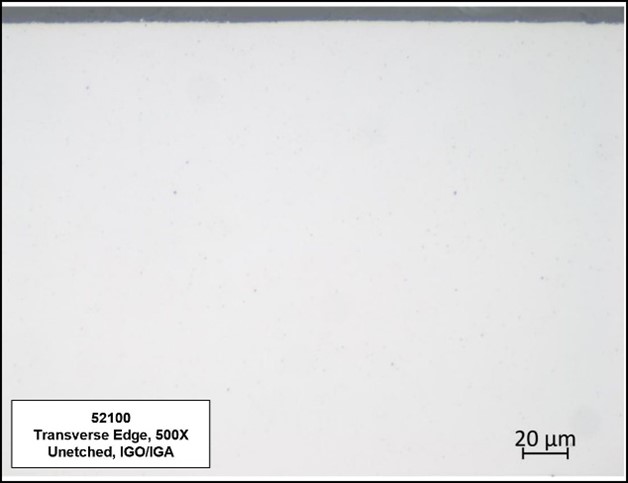
La RA se puede medir de manera metalográfica con un microscopio óptico. En la mayoría de los casos, un metalúrgico con experiencia puede establecer el %RA en el rango hasta del 10-15%, lo cual es más que suficiente para muchas aplicaciones, con el beneficio adicional de que también caracteriza la microestructura.

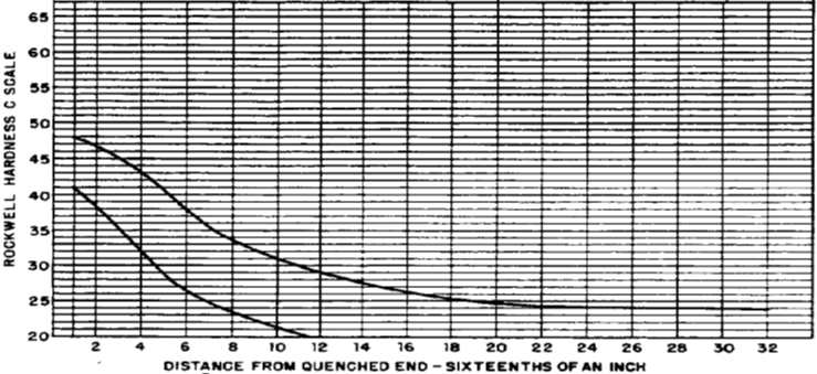
Este método, que implica establecer la fracción de austenita mediante el contraste derivado del comportamiento de grabado o morfología, es de bajo costo; sin embargo, puede ser demorado. En libros de referencia existen tablas y diagramas que ayudan a determinar el porcentaje de austenita retenida utilizando métodos comparativos. La microscopía óptica es subjetiva ya que depende del individuo y la interpretación que haga de la muestra bajo el microscopio.

Figura 3. Ejemplo de la técnica para medir los picos de %RA

Métodos alternos

Los tratadores térmicos también disponen de otros varios métodos de medición de la RA. Entre los más comunes se encuentran:

La inducción magnética: Aquí se magnetiza una muestra al punto de saturación y se mide la polarización de saturación. Con esto, se calcula la diferencia entre la saturación medida y la saturación teórica de la RA utilizando la ecuación.

La inducción magnética no es destructiva y ofrece un rango más alto y amplio que el de la microscopía óptica (1-30%). Sin embargo, al ser una medición de volumen, es necesario que el instrumento sea calibrado a los materiales específicos, junto con sus tratamientos térmicos y geometrías, lo cual exige mucho tiempo y depende en un alto grado de la habilidad del técnico.

Difracción de electrones por retrodispersión (EBSD, por sus siglas en inglés): Utilizar este método de medición de RA implica ubicar la muestra en un microscopio electrónico de barrido (SEM, por sus siglas en inglés) para caracterizar la estructura cristalográfica al igual que la microestructura. Las mediciones de RA con base en esta técnica no suelen ser muy precisas y dependen de la correcta preparación de la muestra. Adicionalmente, es un método destructivo y arroja una medida sobre un volumen muy pequeño.

En conclusión

El medir acertadamente el nivel de austenita retenida permite que tanto el ingeniero de diseño como el metalúrgico maximicen los efectos benéficos que ofrece, al mismo tiempo evitando sus consecuencias negativas. El tratador térmico, por su parte, deberá tener en cuenta la química del material y las variables del proceso de tratamiento térmico tales como la temperatura de austenización, la rapidez de enfriamiento, los tratamientos criogénicos o de congelación profunda y las temperaturas de templado.

Referencias

Errichello, Robert, Robert Budny, and Rainer Eckert. “Investigations of Bearing Failures Associated with White Etching Areas (WEAs) in Wind Turbine Gearboxes.” Tribology Transactions 56, no. 6 (2013): 1069–1076.

GNR, Analytical Instruments Group. “AreX Diffractometer: GNR Proposal for measuring Retained Austenite in the industrial domain and in laboratory.”

Herring, Daniel H., Atmosphere Heat Treatment. Volume I. Chicago: BNP Media, 2014.

Agradecimientos

Queremos agradecer a los siguientes contribuyentes por su aporte en el desarrollo de este artículo: Thomas Wingens, presidente y especialista en Heat Treat, WINGENS CONSULTANTS; Dennis Beauchesne, gerente general, ECM USA; Tim Moury, presidente & CEO, Marco DeGasperi, gerente técnico, Jeff Froetschel, vicepresidente y director financiero, Verichek Technical Services, Inc.; y Dan Herring, The Heat Treat Doctor®, The HERRING GROUP, Inc.


Métodos para la medición de la austenita retenida Read More »

Methods of Measuring Retained Austenite

Most heat treaters recognize the importance of measuring retained austenite (RA), yet many opt not to perform these measurements due to time and/or cost constraints. This Technical Tuesday installment explains why performing RA measurements is necessary, the pros and cons of traditional measurement techniques, and the benefits of using more current and in plant technologies.

This informative piece was first released in Heat Treat Today’s March 2025 Aerospace Heat Treating print edition. To read the article in Spanish, click here.


Why Retained Austenite Percentage Matters

Before examining measurement methodologies, it is important to understand the fundamentals of retained austenite and why the percentage of retained austenite (RA%) matters.

Austenite that does not transform to martensite upon quenching is called retained austenite (RA). In simple terms, retained austenite (Figure 1) occurs when steel is not fully quenched to the martensite finish (Mf) temperature; that is, low enough to form 100% martensite. Because the Mf is below room temperature in most alloys containing more than 0.30% carbon, significant amounts of retained austenite may be present within the martensite at room temperature (Herring, Atmosphere Heat Treatment).

When it comes to RA%, there is often a delicate balance between its beneficial effects (an increase in the life of certain manufactured components) and its negative attributes (the creation of parts that are prone to cracking and failure). For this reason, it is crucial that heat treaters achieve the optimal RA% for the intended application.

For example, in the aeronautics and astronautics industries, RA levels are often specified to be under 8% and, for devices such as bearings and linear actuators, RA under 3% and as close to zero as possible is required. In other applications, however, such as large gearing for power generation, wind energy, and performance platforms, in the range of 15–30% or more RA has been found beneficial (Errichello et al., “Investigations of Bearing Failures”). Also, high RA% has been found beneficial for bearings that will be subjected to contaminated lubricants.

Figure 1. 12CrNi3 (similar to SAE/AISI 9310) bearing roller path surface microstructure consisting of tempered martensite with evidence of retained austenite (white areas)

Marco DeGasperi, technical manager at Verichek, weighed in on this, noting that for fuel injectors, small pieces in medical applications, and high-level, high-volume applications like wear plates in the mining industry, RA% is critical. He summarized with the statement, “When you’re applying pressure and motion to anything that’s fine-tuned … If you have ‘precision’ in your name, you probably want [an RA% measurement device].”

The very characteristics that give retained austenite many of its unique properties are those responsible for significant problems in service. We know that austenite is the normal phase of steel at high temperatures, but not at room temperature. Because retained austenite exists outside of its normal temperature range, it is metastable. This means that in service, factors such as temperature, stress, and even time will see it transform into untempered martensite. In addition, a volume change (increase) accompanies this transformation and induces a great deal of internal stress in a component, often manifesting itself as cracks, which leads to parts failing in the field.

RA% is also important not only because of its influence on dimensional stability but on mechanical properties such as yield strength, fatigue strength, toughness, and machinability (Herring, Atmosphere Heat Treatment). For example, looking in the automotive industry, DeGasperi gives an example of the consequences of having too high or too low RA%: “Let’s say pieces in a transmission or a transfer case; this is when gears start breaking or you get issued wide-end recalls. And then usually the supply chain all starts blaming the guy before them when nobody throughout the supply chain has actually tested the parts themselves.”

Alternatively, in some cases, finely dispersed RA helps the material resist the propagation of fatigue cracks and improves rolling contact fatigue stress, so balancing the amount of RA is important in many applications. Also, the correct RA% is essential for quality control, and proper control and accurate measurement of RA% in steel alloys is crucial to guaranteeing the quality and safety of finished components, as well as protecting the reputation and profitability of heat treaters and manufacturers.

RA Measurement Methods

Accurate RA measurements are critical to determine whether the correct balance of retained austenite and martensite exists within a given part. Several RA measurement methodologies are available to heat treaters, each having their own unique set of advantages and disadvantages. For heat treaters, understanding why it is crucial to measure the percentage of RA is only half the battle. Finding a cost-effective, fast, and accurate measurement method is the other half.

X-Ray Diffraction: The Best and Most Accurate Method

Figure 2a. An ArexD table-top unit from GNR

X-ray diffraction, which is used to identify and quantify phases in a material, is considered the most accurate method of RA measurement in steels as it can precisely determine RA levels down to the range of approximately 0.5–1% (GNR, “AreX Diffractometer,” 3). In X-ray diffraction, different crystalline phases have different diffraction patterns, allowing them to be identified and measured. In addition to phase analysis, X-ray diffraction can be used to analyze microstructural features such as texture, residual stress, and grain size.

Today, X-ray diffraction is a non-destructive, safe solution that can sample a much larger region than many other available methods and does not involve much sample preparation and analysis, making it a more efficient and effective solution. This is the option of choice for a company that needs to test RA with expected readings under 10%.

The current generation of X-ray diffractometers are tabletop sized, weighing about 25 lbs. With models under $100,000, they are also cost-effective when compared to traditional X-ray diffractometers ($200,000), which were sometimes problematic in the presence of additional phases and reflections due to grain size, carbides, or textures that could cause disturbances and variances in measurement. The new generation of X-ray equipment compensates for these obstacles via the use of multiple diffraction peaks to minimize the effects of preferred orientation and detect interference from carbides.

2b. An ArexD table-top unit from GNR

Modern X-ray diffraction machines can collect up to seven diffraction peaks (three for ferrite/martensite phase and four for austenite phase) and then determine the volume percent concentration of RA in the sample by comparing the intensities of the peaks and analyzing the peak ratios in accordance with the ASTM E975-22 (standard practice for X-ray determination of retained austenite in steel with near random crystallographic orientation).

The use of today’s X-ray diffraction equipment is not complicated. It can be measured in under three minutes by simply placing the sample in the machine and pressing the start button. These X-ray diffractometers measure various-sized samples and use intuitive software so the measurement can be performed quickly, accurately, and efficiently by any technician — with or without prior metallurgical or diffraction experience.

Optical Microscopy — A Time-Proven Method

RA can be measured metallographically with an optical microscope. An experienced metallurgist can usually determine RA% down to approximately 10–15% RA. For many applications, this is more than adequate and has the added benefit of characterizing the microstructure as well.

This method, which involves determining the austenite fraction using contrast from etching behavior or morphology, is low cost, however, it can be somewhat time consuming. Charts and diagrams in reference books are available to help determine the percentage of retained austenite by comparative methods. Optical microscopy is subjective as it is dependent upon the individual and their interpretation of the sample under the microscope.

Figure 3. Example of how RA% peaks are measured

Alternative Methods

Several other methods for measuring RA are available to heat treaters. The most common of these methods includes:

Magnetic Induction: Here, a sample is magnetized to saturation and the saturation polarization is measured. The difference between measured and theoretical saturation of the RA can then be calculated using this equation:

Magnetic induction is non-destructive and offers a higher, broader range than optical microscopy (1–30%). However, because it is a volume measurement, the instrument needs to be calibrated to the specific materials, heat treatment, and geometries, which is time consuming and highly dependent on the skill of the technician.

Electron Backscatter Diffraction (EBSD): Using this RA measurement method involves placing a sample in a Scanning Electron Microscope (SEM) to characterize the crystallographic structure as well as the microstructure. RA measurements using this technique are not particularly accurate and are reliant upon proper sample preparation. Additionally, it provides a very small measure volume and is a destructive test method.

Conclusion

Accurate measurement of the level of retained austenite allows both the design engineer and metallurgist to maximize its beneficial effects without suffering from its negative consequences. On the part of the heat treater this means taking into account the material chemistry and the heat treat process variables such as austenitizing temperature, quench rate, deep freeze or cryogenic treatments, and tempering temperatures.

References

Errichello, Robert, Robert Budny, and Rainer Eckert. “Investigations of Bearing Failures Associated with White Etching Areas (WEAs) in Wind Turbine Gearboxes.” Tribology Transactions 56, no. 6 (2013): 1069–1076.

GNR, Analytical Instruments Group. “AreX Diffractometer: GNR Proposal for measuring Retained Austenite in the industrial domain and in laboratory.”

Herring, Daniel H., Atmosphere Heat Treatment. Volume I. Chicago: BNP Media, 2014.

Acknowledgments

We’d like to thank the following contributors for the support of this article: Thomas Wingens, President & Heat Treat Specialist, WINGENS CONSULTANTS; Dennis Beauchesne, General Manager, ECM USA; Tim Moury, President & CEO, Marco DeGasperi, Technical Manager, Jeff Froetschel, VP & CFO, Verichek Technical Services, Inc.; and Dan Herring, The Heat Treat Doctor®, The HERRING GROUP, Inc.

This article is provided by the Heat Treat Today Editorial Team.


Methods of Measuring Retained Austenite Read More »

Quench Oil Management: AMS2759 & CQI-9

Given safety and performance concerns in the aerospace sector, it may be beneficial to consider quench testing that uses CQI-9 as well as AMS2759 since the automotive standard focuses on safety. Read on to understand the different approaches between these two standards in this Technical Tuesday installment, written by Michelle Bennett, quality assurance senior specialist, and Greg Steiger, senior account manager, both at Idemitsu Lubricants America.

This informative piece was first released in Heat Treat Today’s March 2025 Aerospace Heat Treating print edition.


In today’s world, there are many different quality systems available to heat treaters. Many of these, such as ISO, are quality management systems. These quality management systems are an important piece of running a successful business. However, to successfully run a heat treat business and compete in either the North American automotive market or the aerospace market, a heat treater must conform to either CQI-9 or AMS2759, or, in cases where a company processes both automotive and aerospace parts, both. This article will explain the requirements for both CQI-9 and AMS2759. It will also explain the differences between the two quality standards and any additional testing that could benefit a heat treater or how they operate their quench tank.

AIAG’s CQI-9

The Automotive Industry Action Group (AIAG) is a non-profit group of over 800 automotive OEMS, parts manufacturers, and service providers who oversee the requirements for CQI-9. The 4th edition is the most current edition of CQI-9. As an internal audit process, CQI-9 covers most of the heat treating process. Section 3.14 specifies the quench oil and water-soluble polymer requirements. An oil quenchant requires that the in-use oils be tested every six months and the testing must include water content, percent suspended solids, total acid number, viscosity, flash point, and cooling curve. The specification range and warning limits are based on the vendor’s requirements and recommendations. For water-based polymers, there are two tests required: concentration and quenchability. The standard does not specify a test for quenchability, however, it does make a few suggestions such as a cooling curve, viscosity, and titration.

For water-based polymers, there are two tests required: concentration and quenchability. The standard does not specify a test for quenchability, however, it does make a few suggestions such as a cooling curve, viscosity, and titration.

All the required testing of the quenchant is designed to achieve consistent metallurgy for safety reasons. Viscosity is monitored to look for oxidation or heat decomposition of the oil. Degradation can be in the form of oxidation, thermal breakdown, or the presence of various contaminants. Increased oil viscosity typically results in decreased heat transfer rates. A decrease in viscosity may indicate contamination. Some suspended solids are to be expected during the quenching process, but the majority of them should be filtered or centrifuged from the process. If the quantity of these contaminants becomes too high, then it can both affect the brightness of the parts, and the parts can get soft spots as the contaminants may not cool the parts at the same rate.

Water and flash point are both monitored for safety. If the flash point drops below the accepted range or the water content is above the acceptable range, these can cause fires during the operation. Water can also show issues with the equipment or the procedure such as leaking of anything that is water cooled, such as the outer door on a furnace. Acid value is monitored to degradation of the oil. As the oil breaks down and oxidizes, the acid value will increase. This can cause the maximum cooling rate to increase and can cause cracking or distortion on the parts. Carbon residue can be measured for two reasons. If the result is below the specification, it can show that the quench speed improver is being broken down or dragged out of the system. If the result is higher than the specification, it can show the formation of sludge, which will impact the brightness of the parts.

For water-based quenchants, the most common test items include pH, refractive index or brix, viscosity, and concentration calculation. Sometimes additional test items can be added, such as biological testing, to help determine and correct current issues.

Table 1. CQI-9 vs. AMS2759 quenchant requirements

SAE’s AMS2759

Just as AIAG is a non-profit business group responsible for CQI-9, SAE International is a non-profit organization responsible for AMS2759. The most recent revision of AMS2759 is Revision G. AMEC (the Aerospace Materials Engineering Committee) is responsible for maintaining this standard. Unlike CQI-9, AMS2759 requires a certificate of conformance for all shipments. Section 3.10.3 begins the requirements for quenchant testing and quenchant deliveries. Viscosity, flash point, and temperature at the maximum cooling rate must be reported on the certificate of compliance when dealing with mineral oil quenchants. For a polymer, the requirements are that the pH of the neat polymer and the neat viscosity of the polymer must both be reported on the certificate. Also required on the polymer certificate are the viscosity, pH, and the temperature at the maximum cooling rate for polymers at 20% dilution by weight.

Similarly to CQI-9, AMS requires that the in-use quenchants be tested biannually. This standard, however, only requires the cooling rate and temperature at max cooling rate be tested, as well as any additional tests the supplier recommends. The AMS2759 specification does not have set limitations on the cooling rate and temperature. Instead, the specification sets the allowed upper and lower deviations from the supplier’s standard for the maximum cooling rate and the temperature at the maximum cooling rate for both oils and water-soluble polymers. The supplier should have calculated the average max cooling rate and average temperature at max cooling rate using many different blend lots and multiple test runs. This average will not vary or change based on current production values or the values for the batch that the client is currently using (Table 1).

Although both standards require having the quenchant tested bi-yearly, most quenchant suppliers encourage their clients to submit their furnace samples for testing quarterly. This ensures that the medium is being monitored frequently, and if a sample is missed or late when sampling quarterly, then the client is still within compliance for the six month testing requirements.

However, because many of the test parameters in CQI-9 are run for safety reasons along with performance reasons, it is highly advised that aerospace heat treaters should run the full suite of CQI-9 testing along with the AMS2759 testing.

Taking a Quench Sample

There are many different quench methods and both standards allow for any of the following variations: ASTM D6200, ISO 9950, JIS K2242, ASTM D6482, or ASTM D6549. The type of testing that is going to be conducted will determine the size of sample that will be needed. For just this quench testing, the volume of sample needed ranges from 250 milliliters to 2 liters.

As always, when taking samples, it is important to be sure to get a good representative sample of the current quenchant being used in the process. The agitation needs to be running and collected in a clean and dry container. The sampling site should be the most convenient location to safely obtain a sample. It should also be the same location for every sample. The lid also needs to be put on before the oil cools too much because the container will draw in moisture and condensation as the oil cools if it is open to the atmosphere.

Conclusion

When examining the standards, there is one basic commonality: the need to run a complete cooling curve every six months. There is also a large difference in that AMS2759 does not require the full suite of testing that CQI-9 does. However, because many of the test parameters in CQI-9 are run for safety reasons along with performance reasons, it is highly advised that aerospace heat treaters should run the full suite of CQI-9 testing along with the AMS2759 testing. For automotive heat treaters, the maximum cooling rate and the temperature at maximum cooling rate is something that can be reported in the normal D6200 cooling curve test.

For manufacturers heat treating parts for aerospace, automotive, or both markets, we recommend quarterly quench samples at a minimum. The primary reason for more frequent testing is safety. Also, with the current labor shortage, heat treaters are busier than ever. If quench samples are routinely taken on a quarterly basis and are somehow missed and forgotten, there is still time to take another sample and remain in CQI-9 and AMS2759 compliance.

Remaining in compliance of these two important standards requires a lot of hard work from both the heat treater and the quenchant provider. Unless the quenchant supplier is working together in a true partnership, it will be very difficult to remain in compliance with the requirements for CQI-9 and AMS2759. But with routine monitoring, heat treaters can help to ensure quenchant and equipment have a longer life and achieve ever-tightening requirements from clients.

About The Authors:

Michelle Bennett
Quality Assurance Senior Specialist
Idemitsu Lubricants America

Michelle Bennett is the quality assurance senior specialist at Idemitsu Lubricants America, supervising the company’s I-LAS used oil analysis program. Over the past 12 years, she has worked in the quality control lab and the research and development department. Her bachelor’s degree is in Chemistry from Indiana University. Michelle is a recipient of Heat Treat Today’s 40 Under 40 Class of 2023 award.

Greg Steiger
Senior Account Manager
Idemitsu Lubricants America

Greg Steiger is the senior account manager at Idemitsu Lubricants America. Previous to this position, Steiger served in a variety of technical service, research and development, and sales and marketing roles for Chemtool Incorporated, Witco Chemical Company, Inc., D.A. Stuart Company, and Safety-Kleen, Inc. He obtained a BS in Chemistry from the University of Illinois at Chicago and recently earned a master’s degree in Materials Engineering at Auburn University. He is also a member of ASM International.

For more information: Contact Michelle Bennett at mbennett.8224@idemitsu.com or Greg Steiger at gsteiger.9910@idemitsu.com.


Quench Oil Management: AMS2759 & CQI-9 Read More »

The Future of Vacuum Oil Quenching

Despite years of research and development that resulted in several important technological innovations, the constraints of high-pressure gas quenching are ever more evident. In today’s Technical Tuesday, Robert Hill, FASM president of Solar Atmospheres of Western PA, addresses the creation of a new, robust style of vacuum oil quench furnace. The results challenge the schematics in how the next generation of oil quench furnaces should be designed, built, and operated.

This informative piece was first released in Heat Treat Today’s November 2024 Vacuum print edition.


Introduction

After decades of research and development that resulted in several important technological innovations, the constraints of high-pressure gas quenching are ever more evident. Gas cooling runs into efficacy issues when compared to liquid quenchant cooling, chiefly for heavier cross sections. This stays true even when using specialized inert gas blends and heightened gas pressures.

Additionally, it is undeniable that stringent liquid quench Aerospace Material Specifications (AMS) standards for certain aerospace alloy steels will never change. In fact, many industry standards (e.g., SAE/AMS and U.S. defense standards) and client specifications often mandate oil quenching of alloys or component parts.

To meet the demand for an effective, sustainable liquid quench solution, Solar Manufacturing with Solar Atmospheres engineers worked through the tumultuous period of the pandemic to create a new, robust style of vacuum oil quench furnace. Their work culminated in a vacuum oil quench furnace with a 36″ x 36″ x 48″ hot zone that operates up to 2000°F and can accommodate a weight capacity of 2000 lbs. With high uptime reliability and excellent metallurgical results, the NEO™ represents a paradigm shift in how the next generation of oil quench furnaces should be designed, built, and operated.

Rigorous Design for Metallurgical Excellence

The next generation of oil quench furnaces heralds an era of metallurgical excellence. This is made apparent across three key measures: control over surface contamination, prevention of parts cracking, and flexible processing of dissimilar materials.

No Surface Contamination

Figure 2. Loading in the NEO furnace
Source: Solar Atmospheres of Western PA

By implementing a vacuum design to the oil quench furnace, the research team avoided issues faced by traditional atmosphere oil quench furnaces, such as surface contamination and intergranular oxidation/intergranular attack (IGO/IGA). Additionally, they meticulously addressed design concerns regarding oil backstreaming in the new multichambered vacuum system. After two years of usage, the hot zone has remained pristine and oil-free.

By effectively removing the possibility of any surface contamination, both IGO and decarburized or carburized surfaces on oil quenched components are eliminated. These critical metallurgical features are unattainable in traditional gas-fired Endothermic batch furnace equipment.

Precision Prevents Part Cracking

To eliminate the potential of part cracking, quench oil temperatures should be able to be maintained between 140°F to 180°F ±5°F, which enhances consistent and repeatable metallurgical results. Furthermore, having the furnace designed so that quench oil recirculates within a closed loop oil to air cooling system keeps water contamination from infiltrating the oil.

No Carbon Content Matching

The next generation of vacuum oil quench furnaces should also have highly controllable atmospheres, devoid of oxygen, which will remove the need to mechanism, which has demonstrated flawless performance for over two years.

Additionally, it is imperative that these furnaces be capable of using more conventional quench oil. A good quench needs excellent vapor pressure, powerful enough to allow the oil to vaporize. Furnaces can be designed with this in mind, allowing operators to save costs by using more conventional quench oils. For example, after rigorous laboratory experimentation into the vaporization of various quench oils at different pressures and temperatures, it was decided to purchase 3000 gallons of Houghton G quench oil, versus the “vacuum only” quench oils that are currently on the market today.

Figure 3. A display of a variety of parts which can be processed in the same run
Source: Solar Atmospheres of Western PA

The next generation of oil quench furnaces should also finally provide metallurgical and quality engineers the ability to thermocouple the oil quenched parts in accordance with AMS2750 Rev H standards. Being able to monitor part temperature with up to twelve (12) data points, as defined by the latest AMS2750 revision, ensures thorough and precise thermocouple monitoring, bolstering control and repeatability.

Lastly, in a hermetically sealed furnace, another layer of control should be established through installing an internal camera. With “eyes” into the furnace, the operator will be able to watch the load transfer in real time from a control panel.

These operational attributes are on full display in the example of an automated austenitized cycle: At the completion of the cycle, the specially-designed transfer mechanism delivers precisely heated parts from the hot zone to the 3000-gallon oil quench chamber consistently within 20 seconds — all without the expulsion of flames and the discharge of smoke.

Oil flames and smoke are no longer acceptable realities in heat treatment operations. Unfortunately, the heat treating industry has been misled in the belief that a catastrophic disaster will never happen to them. There have been multiple “total losses,” mostly due to oil quench fires and explosions. Recently, it is well known that if an insurance adjuster sights a flame or smoke within a plant, they are reluctant or may even refuse to write the policy.

Vacuum furnaces offer a safe, contained alternative to the harmful open emissions and dangerous working conditions. For operations where the safety and the well being of the workforce are paramount, vacuum furnaces eliminate the risks associated with open flame exposure, explosivity, and skin burns.

Yet the next generation of vacuum oil quench furnaces should also open at both ends at the end of a cycle to expose it to atmosphere. Full air exchange mitigates the potential hazards of confined spaces.

Figure 5. Top view showing innovative design features for the next generation of vacuum oil quench furnaces
Source: Solar Atmospheres of Western PA

Meeting Environmental Demands

With ever more stringent environmental regulations, the next generation of vacuum oil quench furnaces will play a pivotal role in reducing the carbon footprint of the heat treating industry. It has been estimated that 80% of fuel used for heat treatment could be replaced by electricity, thus drastically reducing CO2 emissions: “When you burn something that contains carbon, you get carbon dioxide that you either must take care of or release into the atmosphere. With electric heating, you do not have any exhaust.”

The second column in the chart on page 30 addresses the multiple environmental concerns associated with traditional batch IQ gas-fired oil quenching furnaces. The third column outlines the advantages of the design for the next generation of oil quench furnaces, which embraces electric heating as a sustainable alternative to fossil fuels. As sustainability pressures continue to mount, governments, clients, and primes alike will continue to flow down requirements on how heat treaters plan to reduce their carbon footprints.

Figure 6. Safety hazards in operating atmosphere furnaces
Source: The Monty

Conclusion

As the demands for metallurgical precision, safety, and environmental sustainability continue to mount, Solar’s new vacuum oil quench furnace emerges as a representative of the next generation of vacuum oil quenching technology. Characterized by unparalleled efficiency, precision, and sustainability, such furnaces will continue to lead the industry toward a future defined by cleanliness, safety, and environmental stewardship.

Table 1. Data from the AICHELIN Group
Source: Solar Atmospheres of Western PA

References

Kanthal, “Heat Treatment CO2 Emissions cut by 50 percent by using electricity” (April 2019), https://www.kanthal.com/en/knowledge-hub/inspiring-stories/heat-treatment-co2-emissions-cut-by-50-percent-by-using-electricity/.

Aichelin Group, “CO2 Footprints and the Heat Treat Industry,” The Monty (January 2024).

About the Author:

Robert Hill, FASM
President
Solar Atmospheres of Western PA

Robert Hill, FASM, began his career with Solar Atmospheres in 1995 at the headquarters plant in Souderton, PA. In 2000, Hill was assigned the responsibility of starting the second plant in Hermitage, PA, where he has specialized in the development of large furnace technology and titanium processing capabilities. Additionally, he was awarded the prestigious Titanium Achievement Award in 2009 by the International Titanium Association.

For more information: Contact Robert at bob@solaratm.com


The Future of Vacuum Oil Quenching Read More »

Consulta a The Heat Treat Doctor®:¿Cómo determinar cuál medio detemple utilizar?

The Heat Treat Doctor® ha vuelto para ofrecer sabios consejos a los lectores de Heat Treat Today y para responder a suspreguntas sobre el tratamiento térmico, brazing, sinterizado y otros tipos de procesamiento térmico, así como preguntassobre metalurgia, equipos y problemas relacionados con los procesos.

The Heat Treat Doctor® has returned to offer sage advice to Heat Treat Today readers and to answer your questions about heat treating, brazing, sintering, and other types of thermal treatments as well as questions on metallurgy, equipment, and process-related issues.

This article was originally published in Heat Treat Today‘s September 2024 People of Heat Treat print edition.

To read the article in English, click here.


El temple es un paso fundamental en el proceso de tratamiento térmico. Y si bien el especialista en tratamiento térmico suele tener varias opciones disponibles, existe un delicado equilibrio entre lo que está disponible para nosotros y cómo podemos optimizar sus características de rendimiento para cumplir con los requisitos/especificaciones de nuestros clientes. Se deben tener en cuenta cuidadosamente el material, el diseño de la pieza (geometría), los requisitos previos y posteriores de manufactura, la carga, el cambio dimensional permitido (es decir, la distorsión) y el proceso como tal. Conozcamos más.

Medios de temple: una breve Descripción

Los medios de temple actuales ofrecen una amplia gama de capacidades que, en algunos casos, se traslapan. Sin embargo, en un nivel fundamental, la función de un medio de temple es extraer calor de la superficie de la pieza para cumplir con una velocidad crítica de enfriamiento especificada y con ello lograr la microestructura necesaria para lograr las propiedades mecánicas y físicas requeridas. En el temple de aceros, por ejemplo, se debe evitar pasar por la “nariz” de la curva de transformación-tiempo-temperatura (TTT) si el resultado final deseado es una microestructura martensítica (o bainítica). Por el contrario, la velocidad de enfriamiento para un proceso de normalización requiere enfriamiento “al aire”, un término que a menudo se malinterpreta y que abordaremos en una discusión futura.

Figura 1. Medios de Temple comunes y su efecto en la distorsión (1)

Sin embargo, un medio de temple (Figura 1) es más que solo su velocidad de enfriamiento. Los medios de temple deben ser estables durante su vida útil, especialmente con respecto a la degradación (por ejemplo, oxidación), ser seguros, ser fáciles de arreglar y mantener, tener un alto punto de vaporización, idealmente no interactuar con la superficie de la pieza, usarse dentro de su rango de rendimiento óptimo, tener una larga vida útil, eliminarse fácilmente mediante limpieza después del temple y ser rentables.

A manera de una caracterización muy amplia, los medios de temple se pueden dividir en las siguientes categorías generales:

  • Medios de temple líquidos (p. ej., a base de agua, aceites, polímeros, sales fundidas y metales fundidos)
  • Medios de temple gaseosos (p. ej., aire, nitrógeno, argón, hidrógeno, vapor, dióxido de carbono, dióxido de azufre, gases reductores, atmósferas protectoras sintéticas o generadas, gases a alta presión)
  • Medios de temple sólidos (p. ej., dados de prensa enfriados, placas y polvos)
  • Medios de medios mixtos (p. ej., temple por aspersión, lechos fluidizados)
Figura 2. Diagrama de Ishikawa (también conocido como de pescado) de las variables de temples (1)

Selección del medio de temple óptimo

Contact us with your Reader Feedback!

Se deben tener en cuenta varios factores al seleccionar el mejor medio de temple. A continuación, se enumeran algunos de los aspectos importantes a tener en cuenta al seleccionar el medio adecuado (Figura 2):

  • Material: composición química, templabilidad, forma (p. ej., barra, placa, forja, fundición), tipo (p. ej., forjado, sinterizado) y limpieza, por nombrar algunos
  • Geometría/diseño de la pieza: forma, tamaño, peso, complejidad
  • Estado de laminación o tratamiento térmico previo: recocido, normalizado, preendurecido, relevado de esfuerzos
  • Estado de tensión: el efecto acumulativo de las operaciones de laminación y las operaciones de fabricación del cliente antes del tratamiento térmico
  • Carga: canastillas (aleación, compuesto C/C, placas de grafito, etc.)
  • Parámetros del proceso: temperatura, tiempo, precalentamiento
  • Selección del equipo: ¿es óptimo o simplemente adecuado para el trabajo?
  • Medio(s) de temple disponibles: sus limitaciones y ventajas

Es importante hablar brevemente aquí sobre dos aspectos del proceso de selección del medio de temple. Primero, observar la diferencia entre dureza y templabilidad (que analizaremos con más detalle en el futuro). Los tratadores térmicos tienden a centrarse en la dureza (ya que podemos medirla fácilmente en nuestro taller), pero la templabilidad es una consideración crítica en la selección del medio de temple. La templabilidad es una propiedad del material independiente de la velocidad de enfriamiento y dependiente de la composición química y el tamaño del grano. Cuando se evalúa mediante pruebas de dureza, la templabilidad se define como la capacidad del material bajo un conjunto dado de condiciones de tratamiento térmico para endurecerse “en profundidad”. En otras palabras, la templabilidad se relaciona con la “profundidad de endurecimiento”, o el perfil de dureza obtenido, no con la capacidad de alcanzar un valor de dureza particular. Cuando se evalúa mediante técnicas microestructurales, la templabilidad se define (para aceros) como la capacidad del acero para transformarse parcial o completamente de austenita a un porcentaje definido de martensita.

Tabla 1. Valores medios e instantáneos del coeficiente de transferencia de calor (3)

En segundo lugar, se debe tener en cuenta tanto el valor medio como el instantáneo del coeficiente de transferencia de calor alfa (α) del medio de temple. Aunque la “potencia” máxima de temple se puede describir mediante el coeficiente de transferencia de calor instantáneo, el coeficiente de transferencia de calor promedio (Tabla 1) proporciona una mejor comparación relativa de los diversos medios de temple, ya que representa el valor del coeficiente de transferencia de calor en todo el rango de enfriamiento (desde el inicio hasta el final del temple). Es importante recordar que la capacidad de gestionar (no controlar) la distorsión es un delicado acto de equilibrio entre la extracción uniforme del calor y la transformación adecuada.

Tabla 2. Clasificación de los aceites de temple (1)

Un ejemplo común: selección de aceite de temple

Los factores importantes a tener en cuenta al seleccionar un aceite de temple, que son válidos en una forma ligeramente modificada para la mayoría de los medios líquidos, son: el tipo de medio (es decir, características del temple, datos de la curva de enfriamiento, nuevo y a lo largo del tiempo); velocidad de temple (consulte a Tabla 2); temperatura de uso; volumen efectivo del tanque de enfriamiento [es decir, la regla de un galón por libra de acero (8,4 L/kg)]; y los requisitos del cliente.

Los factores de diseño del tanque de temple también juegan un papel importante e involucran lo siguiente:

  • Volumen de aceite en el tanque de temple
  • Número de recirculadores o bombas
  • Ubicación de los recirculadores
  • Tipo de recirculadores (velocidad fija ovariable)
  • Disposición de los deflectores internos del tanque (tubos de aspiración, álabes de flujo direccional, etc.)
  • Diseño del elevador de temple (es decir, restricciones de flujo)
  • Dirección del flujo del temple (hacia arriba o hacia abajo a través de la carga)
  • Tamaño de la propela (diámetro, espacio libre en el tubo de aspiración)
  • Máximo incremento dela temperatura (diseño) delaceite después del temple
  • Altura del aceite sobre la carga
  • Intercambiador de calor: tipo, tamaño, tasa de extracción de calor (BTU instantáneos/minuto)
  • Tiempo de recuperación del aceite hasta el set point

Por último, se deben tener en cuenta factores como: la masa de la pieza; la geometría de la pieza (por ejemplo, secciones delgadas y gruesas, esquinas y barrenos afilados, perfil de los dientes del engrane, perfil de la rosca, etc.); espaciamiento de la pieza en la carga; velocidad de flujo efectiva a través del área de temple (vacía y con carga); estado de tensión de operaciones anteriores (de manufactura); operaciones de tratamiento térmico posteriores a realizar (si las hay); carga, incluidas las charolas, las canastillas y el herramental (material y diseño); y el material (composición química y templabilidad).

Reflexiones finales

El temple, considerado por muchos como un tema complejo y multifacético, es un asunto que los especialistas en tratamiento térmico deben supervisar y controlar constantemente. En futuras entregas, analizaremos muchos de los aspectos individuales del temple. Lo importante aquí es reconocer que, si se realiza correctamente, el temple (en cualquier forma) optimizará un tratamiento térmico determinado y ayudará a producir las piezas de la más alta calidad que exigen las industrias a las que prestamos nuestros servicios.

Referencias

Daniel Herring, Atmosphere Heat Treatment, Volume II: Atmospheres | Quenching | Testing (BNP Media Group, 2015).

Bozidar Liscic et al., Quenching Theory and Technology, Second Edition (CRC Press, Taylor Francis Group, 2010).

Daniel Herring, “A Review of Gas Quenching from the Perspective of the Heat Transfer Coefficient,” Industrial Heating, February 2006.

Sobre el autor

Dan Herring
“The Heat Treat Doctor”
The HERRING GROUP, Inc.

Dan Herring ha trabajado en la industria durante más de 50 años y ha adquirido una vasta experiencia en campos que incluyen ciencia de materiales, ingeniería, metalurgia, investigación de nuevos productos y muchas otras áreas. Dan es
autor de seis libros y más de 700 artículos técnicos.

Para más información: Comuníquese con Dan en dherring@heat-treat-doctor.com.

For more information about Dan’s books: see his page at the Heat Treat Store.


Find Heat Treating Products And Services When You Search On Heat Treat Buyers Guide.Com


Consulta a The Heat Treat Doctor®:¿Cómo determinar cuál medio detemple utilizar? Read More »

Ask the Heat Treat Doctor®: How Does One Determine Which Quench Medium To Use?

The Heat Treat Doctor® has returned to offer sage advice to Heat Treat Today readers and to answer your questions about heat treating, brazing, sintering, and other types of thermal treatments as well as questions on metallurgy, equipment, and process-related issues.

The Heat Treat Doctor® ha vuelto para ofrecer sabios consejos a los lectores de Heat Treat Today y para responder a suspreguntas sobre el tratamiento térmico, brazing, sinterizado y otros tipos de procesamiento térmico, así como preguntassobre metalurgia, equipos y problemasrelacionados con los procesos.

This article was originally published in Heat Treat Today‘s September 2024 People of Heat Treat print edition.

To read the article in Spanish, click here.


Quenching is a critical step in the heat treating process. And while there are often several choices available to the heat treater, a delicate balance exists between what is available to us and how we can optimize its performance characteristics to meet our client’s requirements/specifications. Material, part design (geometry), pre-and post-manufacturing requirements, loading, allowable dimensional change (i.e., distortion), and the process itself must be taken into careful consideration. Let’s learn more.

Quenchants — A Brief Overview

Today’s quenchants offer a broad and, in some instances, overlapping range of capabilities. But at a fundamental level, the role of a quenchant is to extract heat from the part surface to meet a specified critical cooling rate and achieve the desired microstructure in the component part necessary to achieve the required mechanical and physical properties. In hardening of steels, for example, one must miss the “nose” of the time-temperature transformation (TTT) curve if the desired end-result is a martensitic (or bainitic) microstructure. By contrast, the cooling rate for a normalizing process requires cooling in “still air” — a term that is often misunderstood and which we will cover in a future discussion.

Figure 1. Common types of quenchants and their effect on distortion (See Reference 1)

However, a quenchant (Figure 1) is more than just its cooling rate. Quenchants should be stable over their service life, especially with respect to degradation (e.g., oxidation), be safe, be easy to service and maintain, have a high vaporization point, ideally not interact with the part surface, be used within their optimum performance range, have long life, be easily removed by cleaning after quenching, and be cost effective.

As a very broad-based characterization, quenchants can be divided into the following general categories:

  • Liquid quenchants (e.g., water-based, oils, polymers, molten salts, and molten metals)
  • Gaseous quenchants (e.g., air, nitrogen, argon, hydrogen, steam, carbon dioxide, sulphur dioxide, reducing gases, protective atmospheres — synthetic or generated, high-pressure gases)
  • Solid quenchants (e.g., water-cooled dies, plates, powders)
  • Mixed media quenchants (e.g., mist or fog quenching, fluidized beds)
Figure 2. Ishikawa (aka fishbone) diagram of quenching variables (See Reference 1)

Selection of the Optimal Quench Medium

Contact us with your Reader Feedback!

Various factors must be taken into consideration when selecting the best quench medium. The following are some of the important considerations when selecting the proper quench medium (Figure 2):

  • Material — chemistry, hardenability, form (e.g., bar, plate, forging, casting), type (e.g., wrought, powder metal), and cleanliness to name a few
  • Part geometry/design — shape, size, weight, complexity
  • Mill or preheat treatment condition — annealed, normalized, pre-hardened, stress-relieved
  • Stress state — the cumulative effect of both mill operations and customer manufacturing operations prior to heat treatment
  • Loading — baskets (alloy, C/C composites, graphite plates, etc.)
  • Process parameters — temperature, time, preheating
  • Equipment selection — is it optimal or simply adequate for the job?
  • Quench medium(s) available — their limitations as well as their advantages

It is important to talk briefly here about two aspects of the quench medium selection process. First, note the difference between hardness and hardenability (which we will discuss in more detail in the future). Heat treaters tend to focus on hardness (since we can easily measure it in our shops), but hardenability is a critical consideration in quench medium selection. Hardenability is a material property independent of cooling rate and dependent on chemical composition and grain size. When evaluated by hardness testing, hardenability is defined as the capacity of the material under a given set of heat treatment conditions to harden “in-depth.” In other words, hardenability is concerned with the “depth of hardening,” or the hardness profile obtained, not the ability to achieve a particular hardness value. When evaluated by microstructural techniques, hardenability is defined (for steels) as the capacity of the steel to transform partially or completely from austenite to a defined percentage of martensite.

Table 1. Average and instantaneous values of the heat transfer coefficient (See Reference 3)

Second, one must be aware of both the average and instantaneous value of the heat transfer coefficient alpha of the quench medium. Although the maximum quenching “power” may be described by the instantaneous heat transfer coefficient, the average heat transfer coefficient (Table 1) provides a better relative comparison of the various quenching media since it represents the value of the heat transfer coefficient over the entire range of cooling (from the start to the end of quenching). It is important to remember that the ability to manage (not control) distortion is a delicate balancing act between uniform heat extraction and proper transformation.

A Common Example — Quench Oil Selection

Important factors to consider when selecting a quench oil, which hold true in a slightly modified form for most liquid quenchants, are: the type of quenchant (i.e., quench characteristics, cooling curve data — new and over time); quench speed (see Table 2); usage temperature; effective quench tank volume (i.e., the one gallon per pound of steel [8.4 L/kg] rule); and the client’s requirements.

Table 2. Classification of quench oils (See Reference 1)

Quench tank design factors also play an important role and involve the following:

  • Volume of oil in the quench tank
  • Number of agitators or pumps
  • Location of agitators
  • Type of agitators (fixed or variable speed)
  • Internal tank baffle arrangement (draft tubes, directional flow vanes, etc.)
  • Quench elevator design (i.e., flow restrictions)
  • Quenchant flow direction (up or down through the load)
  • Propeller size (diameter, clearance in draft tube)
  • Maximum (design) temperature rise of the oil after quenching
  • Height of the oil over the workload
  • Heat exchanger — type, size, heat removal rate (instantaneous BTU/minute)
  • Oil recovery time to setpoint

Finally, consideration must be given to factors such as: part mass; part geometry (e.g., thin and thick sections, sharp corners and holes, gear tooth profile/modulus, thread profile, etc.); part spacing in the load; effective flow velocity through the quench area (empty and with a load); stress state from prior (manufacturing) operations; post heat treat operations to be performed (if any); loading including the grids, baskets, and fixture (material and design); and the material (chemistry and hardenability).

Final Thoughts

Quenching, considered by many to be a complex and multi-faceted subject, is one heat treaters must constantly monitor and control. In future installments we will be discussing many of the individual aspects of quenching. What is important here is to recognize that done correctly, quenching
(in whatever form) will optimize a given heat treatment and help produce the highest quality parts demanded by the industries we serve.

References

Daniel Herring, Atmosphere Heat Treatment, Volume II: Atmospheres | Quenching | Testing (BNP Media Group, 2015).

Božidar Liščić et al., Quenching Theory and Technology, Second Edition (CRC Press, Taylor Francis Group, 2010).

Daniel Herring, “A Review of Gas Quenching from the Perspective of the Heat Transfer Coefficient,” Industrial Heating, February 2006.

About the Author

Dan Herring
“The Heat Treat Doctor”
The HERRING GROUP, Inc.

Dan Herring has been in the industry for over 50 years and has gained vast experience in fields that include materials
science, engineering, metallurgy, new product research, and many other areas. He is the author of six books and over
700 technical articles.

For more information: Contact Dan at dherring@heat-treat-doctor.com.

For more information about Dan’s books: see his page at the Heat Treat Store.


Find Heat Treating Products And Services When You Search On Heat Treat Buyers Guide.Com


Ask the Heat Treat Doctor®: How Does One Determine Which Quench Medium To Use? Read More »

Heat Treat Radio #112: Lunch & Learn: How To Use a Hardenability Chart  

In this episode of Heat Treat Radio, Doug Glenn discusses the hardenability of materials with guest Michael Mouilleseaux, general manager at Erie Steel LTD. Michael walks us through how to interpret hardenability charts and provides detailed insights on reading these charts, including addressing the importance of understanding the nuances of complicated part geometry. 

Below, you can watch the video, listen to the podcast by clicking on the audio play button, or read an edited transcript.


The following transcript has been edited for your reading enjoyment.

Understanding a Hardenability Chart (01:59)

Doug Glenn: What I’d like to do is talk through this chart and learn how to read this a little bit better. And I’d like to ask questions about it because I’m not familiar with this, and I’m sure there are going to be some listeners and viewers who aren’t familiar with it. This will be just a quick tutorial on how to read these charts.

Go to the upper, right-hand corner. First off, SAE 4320H is the grade of the steel that we’re talking about?

The Heat Treat Lunch & Learn crew: Doug Glenn, Publisher of Heat Treat Today; Michael Mouilleseaux, General Manager at Erie Steel LTD.; Bethany Leone, Managing Editor of Heat Treat Today
Use this chart to follow along with the conversation.
Source of chart: Erie Steel, Ltd.

Michael Mouilleseaux: Correct.

Doug Glenn: Then the table right below that you’ve got percentage C (carbon). Is Mn manganese?

Michael Mouilleseaux: Manganese.

Doug Glenn: Thank you very much. Silicon, nickel, chrome, moly. My question is about those ranges. Is this basically saying the percentage carbon on the far left in 4320H goes anywhere from 0.17–0.23?

Michael Mouilleseaux: That is correct.

Doug Glenn: Okay. So that’s variability right there. All of those are basically telling you what the ranges are in those alloys in this grade of steel?

Michael Mouilleseaux: That is correct.

Doug Glenn: Then you go down to the top columns of this table below, and it says “Approximate diameter of rounds with same as quenched HRC in inches.” Right?

Approximate diameter of rounds with same as quenched HRC in inches
Source: Erie Steel, Ltd.

Michael Mouilleseaux: Yeah. Essentially, the first three rows are for water quenching. And the bottom three are for oil quenching.

Doug Glenn: If you go over to the second major column called “Location in round,” what’s the size of the round we’re working on here?

Michael Mouilleseaux: It can vary. Go down to where it says, “Mild Oil Quench,” then left to “Surface,” then left then go to “2 inches.” Then, go straight down to the bottom, and that’s approximately J5. So, the “Distance from Quenched End — Sixteenths of an Inch” is Jominy position 5.

Michael Mouilleseaux: If you go to Jominy position 5 on the left-hand chart, you can see the hardness limits for that; the maximum is Rockwell C 41, and the minimum is Rockwell C 29. So, the chemistry can vary provided the hardenability at J5 is 29–41.

Doug Glenn: That’s the acceptable range?

Michael Mouilleseaux: That’s the acceptable range. That’s one way of looking at it. The chemistry would allow you to do that.

Now, go back to the chart on the right-hand side and to “Surface,” move down one row to “¾ radius from center,” and go left to two inches. Moving down from there you see that is Jominy position 8. So, the surface of a two-inch round is Jominy position 5, and the ¾ radius is Jominy position 8.

If you go to the hardness chart on the left-hand side, that says that if you had a two-inch round of 4320H, and it was oil quenched, and you check the hardness at ¾ radius, then the expectation is that it would be 23–34.

Now, go back to the same chart that we were just at, and go to the “Center” row of “Mild oil quench.” Continue left to two inches, and that’s J12. Go back to the left-hand chart, and J12 is 20–29 in the center of the part.

So, the surface of the part could be 41, ¾ radius, center of the part would be 34, and the center of the part would be 29.And that would all meet the criteria.

Doug Glenn: The maximum for J5 would be 41.But at J12 you could get a 20 in the middle.

Michael Mouilleseaux: Right. That is one way to look at this chart. But there is another way.

Notice that it says “rounds.”There are some nuances to having flats and rectangles because, if you think about it, for the cross-sectional area of a rectangle, the hardenability is going to be determined by the direction that it is thinnest, not by the direction that it is thickest.

Take a gear tooth, for example: in the chart that we just made up the gear teeth, the root of the gear was about a half inch, just slightly more; and if we go to this same chart, go to “Center” of “Mild oil quench,” and then go to a “0.5 inch,” and when you go straight down, that’s the J3.

Is a gear necessarily a round? Of course, the answer to that is no. So, in complex shapes you can use this data, but you have to interpolate it in order to understand it.

To some extent, the first time you run this, you’re going to say, “I have a gear, and the root is a half inch across. And I know that the J3 is 40. And I’ll run this part, and I’ll section it and I’ll measure it and it’s 40. And I’ll say that’s a good approximation of that.” And experientially, you build confidence in this, that is, it’s your operation, your quenching operation, and your components. It allows you to interpolate these, and they become extremely useful.

So, is it definitive? No. Is it useful? Yes.

Doug Glenn: It gives you a ballpark, right? I mean, it’s giving you something, maybe guardrails.

Michael Mouilleseaux: It gives you a ballpark; it gives you guardrails. And I can tell you that after having run gear product in the same equipment for ten years, I can say that it’s definitive. I can say that if I have this hardenability, and I get this hardenability number for this heat, and these gears are made from this heat of steel, and it has a J3 of 42. If I’m at 38, I know something is going on other than just hardenability. And, at that point, I would suspect my heat treat operation.

Doug Glenn: Yeah. I have one more question about this chart: On the bottom right part of the graph there are two plot lines on there. What do those represent? I was thinking one represented the water quench and the bottom one represents the oil quench.

Plot lines representing maximum hardenability and minimum hardenability
Source: Erie Steel, Ltd.

Michael Mouilleseaux: The top one represents the maximum hardenability. And the lower the lower one represents the minimum hardenability.

Doug Glenn: That’s your band. Okay. Those are basically your values over on the left-hand side then. Very good.

I don’t know about you, but I found that helpful. I really didn’t ever know how to read these tables. So, maybe someone else will find that useful. Thanks, Michael. I appreciate your expertise.

Michael Mouilleseaux: It’s been my pleasure.

About The Guest

Michael Mouilleseaux
General Manager at Erie Steel, Ltd.
Sourced from the author

Michael Mouilleseaux is general manager at Erie Steel LTD. Mike has been at Erie Steel in Toledo, OH, since 2006 with previous metallurgical experience at New Process Gear in Syracuse, NY, and as the Director of Technology in Marketing at FPM Heat Treating LLC in Elk Grove, IL. Having graduated from the University of Michigan with a degree in Metallurgical Engineering, Mike has proved his expertise in the field of heat treat, co-presenting at the 2019 Heat Treat show and currently serving on the Board of Trustees at the Metal Treating Institute.

Contact Mike at mmouilleseaux@erie.com.


Search Heat Treat Equipment And Service Providers On Heat Treat Buyers Guide.Com


Heat Treat Radio #112: Lunch & Learn: How To Use a Hardenability Chart   Read More »

All About the Quench and Keeping Cool: Thru-process Temp Monitoring and Gas Carburizing

The future of heat treating requires new manufacturing solutions like robotics that can work with modular design. Yet so also does temperature monitoring need to be seamless to know how effectively your components are being heat treated — especially through being quenched. In this Technical Tuesday, learn more about temperature monitoring through the quench process.

Gas Carburization

Contact us with your Reader Feedback!

Carburizing has rapidly become one of the most critical heat treatment processes employed in the manufacture of automotive components. Also referred to as case hardening, it provides necessary surface resistance to wear, while maintaining toughness and core strength essential for hardworking automotive parts.

Figure 1. Typical carburizing heat treat temperature profile showing the critical temperature/time steps: (i) carburization, (ii) quench, and (iii) temper. (Source: PhoenixTM)

The carburizing process is achieved by heat treating the product in a carbon rich environment (Figure 1), typically at a temperature of 1562°F–1922°F (850°C–1050°C). The temperature and process time significantly influence the depth of carbon diffusion and other related surface characteristics. Critical to the process is a rapid quenching of the product following the diffusion in which the temperature is rapidly decreased to generate the microstructure, giving the enhanced surface hardness while maintaining a soft and tough product core.

The outer surface becomes hard via the transformation from austenite to martensite while the core remains soft and tough as a ferritic and/or pearlitic microstructure. Normally, carburized microstructures following quench are further tempered at temperatures of about 356°F (180°C) to transform some of the brittle martensite into tempered martensite to enhance ductility and grindability.

Critical Process Temperature Control

As discussed, the success of carburization is dependent on accurate, repeatable control of the product temperature and time at that temperature through the complete heat treatment process. Important to the whole operation is the quench, in which the rate of cooling (product temperature change) is critical to achieve the desired changes in microstructure, creating the surface hardness. It is interesting that the success of the whole heat treat process can rest on a process step which is so short (minutes), in terms of the complete heat teat process (hours). Getting the quench correct is not only essential to achieve the desired metal microstructure, but also to ensure that the physical dimensions and shape of the product are maintained (no distortion/warping) and issues such as quench cracking are eliminated.

Obviously, as the quench is so critical to the whole heat treat process, the correct quench selection needs to be made to achieve the optimum properties with acceptable levels of dimensional change. Many different quenchants can be applied with differing quenching performances. The rate of heat transfer (quench rate) of quench media in general follows this order from slowest to quickest: air, salt, polymer, oil, caustic, and water.

Technology Challenges for Temperature Monitoring

When considering carburization from an industry standpoint, furnace heat treat technology generally falls into one of two camps, embracing either air quench (low pressure carburization) or oil quench (sealed gas carburization/LPC with integral or vacuum oil quench). Although each achieves the same end goal, the heat treat mechanisms and technologies employed are very different, as are the temperature monitoring challenges.

To achieve the desired carburized product, it is necessary to control and hence monitor the product temperature through the three phases of the heat treat process. Conventionally, product temperature monitoring would be attempted using the traditional trailing thermocouple method. For many modern heat treat processes including carburization, the trailing thermocouple method is difficult and often practically impossible.1 The movement of the product or product basket from stage to stage, often from one independent sealed chamber to another (lateral or vertical movement), makes the monitoring of the complete process a significant challenge.

With the industry driving toward fully automated manufacturing, furnace manufacturers are now offering the complete package with full robotic product loading that includes shuttle transfer systems and modular heat treat phases to process both complete product baskets and single piece operations. Although trailing thermocouples may allow individual stages in the process to be measured, they cannot provide monitoring of the complete heat treat journey. Testing is therefore not under true normal production conditions, and therefore is not an accurate record of what happens in normal day to day operation.

Figure 2 shows schematic diagrams of two typical carburizing furnace configurations that would not be possible to monitor using trailing thermocouples. The first shows a modular batch furnace system where the product basket is transferred between each static heat treat operation (preheat, carburizing furnace, cooling station, quench, quench wash, temper furnace) via a charge transfer cart. The second shows the same heat treat operation but performed in a continuous indexed pusher furnace configuration where the product basket moves sequentially through each heat treat operation in a semi-continuous flow.

Figure 2.1. Modular batch furnace system (Source: PhoenixTM)
Figure 2.2. Continuous pusher furnace schematic (Source: PhoenixTM)

Thru-process temperature monitoring as a technique overcomes such technical restrictions. The data logger is protected by a specially designed thermal barrier, therefore, can travel with the product through each stage of the process measuring the product/process temperature with short, localized thermocouples that will not hinder travel. The careful design and construction of the monitoring system is important to address the specific challenges that different heat treat technology brings including modular batch and continuous pusher furnace designs (Figure 2).2

The following section will focus specifically on monitoring challenges of the sealed gas carburizing process with integral oil quench. Technical challenges of the alternative low pressure carburizing technology with high pressure gas quench have previously been discussed in an earlier publication.3

Monitoring Challenges of Sealed Gas Carburization — Oil Quench

Figure 3. “Thru-process” temperature monitoring system for use in a sealed carburizing furnace with integral oil quench — (3.1) Monitoring system entering furnace with thermocouple fixed to automotive gears, product test pieces (3.2) System exiting oil quench tank (3.3) System inserted into wash tank with product basket (Source: PhoenixTM)

Presently, the most common traditional method of gas carburizing for automotive steels is often referred to as sealed gas carburizing. In this method, the parts are surrounded by an endothermic gas atmosphere. Carbon is generated by the Boudouard reaction during the carburization process, typically at 1562°F–1832°F (850°C –1000°C). Despite the dramatic appearance of a sealed gas carburizing furnace, with its characteristic belching flames (Figure 3), from a monitoring perspective, the most challenging aspect of the process is not the heating, but the oil quench cooling. For such furnace technology, the historic limitation of “thru-process” temperature profiling has been the need to bypass the oil quench and wash stations, missing a critical process step from the monitoring operation. Obviously, passing a conventional hot barrier through an oil quench creates potential risk of both system damage from oil ingress and barrier distortion, as well as general process safety. However, the need to bypass the quench in certain furnace configurations by removing the hot system from the confined furnace space could create significant operational challenges, from an access and safety perspective.

Monitoring of the quench is important as ageing of the oil results in decomposition (thermal cracking), oxidation, and contamination (e.g. water) of the oil, all of which degrade the viscosity, heat transfer characteristics, and quench efficiency. Control of physical oil temperature and agitation rates is also key to oil quench performance. Quench monitoring allows economic oil replacement schedules to be set, without risk to process performance and product quality.

Figure 4. “Thru-process” temperature monitoring system oil quench compatible thermal barrier design: (1) Robust outer structural frame keeping insulation and inner barrier secure; (2) Internal thermal barrier — completely sealed with integral microporous insulation protecting data logger; (3) Mineral insulated thermocouples sealed in internal thermal barrier with oil tight compression fitting; (4) Multi-channel high temperature data logger; and (5) Sacrificial insulation blocks replaced after each run. (Source: PhoenixTM)

To address the process challenges, a unique thermal barrier design has been developed that both protects the data logger in the furnace (typically three hours at 1697°F/925°C) and also protects during transfer through the oil quench (typically 15 mins) and final wash station (Figure 3). The key to the barrier design is the encasement of a sealed inner barrier with its own thermal protection with blocks of high-grade sacrificial insulation contained in a robust outer structural frame (Figure 4).

Quench Cooling Phases

Monitoring the oil quench in carburization gives the operator a unique insight into the product’s specific cooling characteristics, which can be critical to allow optimal product loading and process understanding and optimization. From a scientific perspective, the quench temperature profile trace, although only a couple of minutes in duration, is complex and unique. From a zoomed in quench trace (Figure 5) taken from a complete carburizing profile run, the three unique heat transfer phases making up the oil quench cool curve can be clearly identified:

Figure 5. Oil quench temperature profile for different locations on an automotive gear test piece shows the three distinct heat transfer phases: (1) film boiling “vapor blanket”, (2) nucleate boiling, and (3) convective heat transfer. (Source: PhoenixTM)
  1. Film boiling “vapor Blanket”: The oil quenchant creates a layer of vapor (Leidenfrost phenomenon) covering the metal surface. Cooling in this stage is a function of conduction through the vapor envelope. Slow cool rate since the vapor blanket acts as an insulator.
  2. Nucleate boiling: As the part cools, the vapor blanket collapses and nucleate boiling results. Heat transfer is fastest during this phase, typically two orders of magnitude higher than in film boiling.
  3. Convective heat transfer: When the part temperature drops below the oil boiling point. the cooling rate slows significantly. The cooling rate is exponentially dependent on the oil’s viscosity.

From a heat treat perspective, the quench step relative to the whole process (hours) is quick (seconds), but it is probably the most critical to the performance of the metallurgical phase transitions and achieving the desired core microstructure of the product without risk of distortion. By being able to monitor the quench step, the process can be validated for different products with differing size, form, and thermal mass. As shown in Figure 6, the quench curve profile over the three heat transfer phases is very different for two different automotive gear sizes.

Figure 6. Oil quench temperature profile for different automotive gear sizes (20MnCr5 case hardening steel) with different thermal masses: Passenger Car Gear (2.2 lbs) and Commercial Vehicle Gear (17.6 lbs) (Source: PhoenixTM)

Summary

As discussed in this article, one of the key process performance factors associated with gas carburization is the control and monitoring of the product quench step. Employing an oil quench, the measurement of such operation is now very feasible as part of heat treat monitoring. Innovations in thru-process temperature profiling technology offer specific system designs to meet the respective application challenges.

References

[1] Dr. Steve Offley, “The light at the end of the tunnel – Monitoring Mesh Belt Furnaces,” Heat Treat Today, February 2022, https://www.heattreattoday.com/processes/brazing/brazing-technical-content/the-light-at-the-end-of-the-tunnel-monitoring-mesh-belt-furnaces/.

[2] Michael Mouilleseaux, “Heat Treat Radio #102: Lunch & Learn, Batch IQ Vs. Continuous Pusher, Part 1,” interviewed by Doug Glenn, Heat Treat Radio, October 26, 2023, audio, https://www.heattreattoday.com/media-category/heat-treat-radio/heat-treat-radio-102-102-lunch-learn-batch-iq-vs-continuous-pusher-part-1/.

[3] Dr. Steve Offley, “Discover the DNA of Automotive Heat Treat: Thru-process Temperature Monitoring,” Heat Treat Today, August 2023, https://www.heattreattoday.com/discover-the-dna-of-automotive-heat-treat-thru-process-temperature-monitoring/.

About the Author

Dr Steve Offley (“Dr O”), Product Marketing Manager, PhoenixTM

Dr. Steve Offley, “Dr. O,” has been the product marketing manager at PhoenixTM for the last five years after a career of over 25 years in temperature monitoring focusing on the heat treatment, paint, and general manufacturing industries. A key aspect of his role is the product management of the innovative PhoenixTM range of thru-process temperature and optical profiling and TUS monitoring system solutions.

For more information: Contact Steve at Steve.Offley@phoenixtm.com.

Find Heat Treating Products And Services When You Search On Heat Treat Buyers Guide.Com

All About the Quench and Keeping Cool: Thru-process Temp Monitoring and Gas Carburizing Read More »

It’s Time for Another Look at Vacuum Oil Quenching

Oil quenching can be a dirty phrase around the heat treat shop. But with vacuum, does it have to be?

This Technical Tuesday article was written by Don Marteeny, vice president of engineering at SECO/VACUUM Technologies, for Heat Treat Today’s November 2023 Vacuum Heat Treating print edition.


There are metallurgical advantages to oil quenching for which there are no gas quench substitutes, but for a time, those advantages only came bundled with some disadvantages that proved incompatible with a growing preference for vacuum processes. This drove vacuum oil quenching (VOQ) to evolve and improve, often faster than its reputation. VOQ has since matured into a convenient, safe, and economical choice, offering today’s vacuum heat treaters all the metallurgical advantages of oil quench without any of the compromises.

A Familiar Scene . . .

Don Marteeny
Vice President of Engineering
SECO/VACUUM Technologies
Contact us with your Reader Feedback!

When oil quenching is mentioned in the break room of any heat treat department, it’s a sure bet that those listening have very similar thoughts. With just the mere mention of oil, their thoughts carry them, not to memories of the first time they helped their dad change the oil in their car in the family garage, but instead to a row of furnaces belching flames from their doors. Next, they are sure to see one of the doors open, and the familiar sensation of hot air moves through their mind. They may – for a moment – expect the smell of salt air, the sand between their toes, and the sun from above.

For many heat treaters, this is but a momentary escape. Soon, the taste and smell of hot oil and metal return them to the moment, and they know they are standing next to a row of batch integral quench (aka, batch IQ or BIQ) furnaces.

It’s about then they will feel the heat of those flames at the end of this furnace line or by the transfer car, wiping the sweat from their brow with a sooty hand and anticipating a return to the break room for a cool drink of water.

Sound familiar? If so, you’re one of the hundreds of heat treaters who has had the pleasure of operating a tried-and-true atmosphere integral quench line; it faithfully does its job, hardening and case hardening steels where oil is the only heavy lifter that can do the job.

Figure 1. Atmosphere oil quenching
Source: SECO/VACUUM Technologies

Necessity Waiting on Invention

While heat treaters have been diligently pumping out oil hardened steels, furnace builders and OEMs alike have been trying to find ways to move away from oil to quenchants that, primarily, reduce distortion, but also that are cleaner, require less processing, and present a safer working environment. Despite their efforts working with modified quenchants – including high pressure gas quenching (HPGQ) in vacuum furnaces – oil quenching has proven robust, maybe even stubborn.

Does that mean we are stuck with the integral quench furnace and its fire-breathing ways? Not necessarily. . . .

Figure 2. D-Type double chamber for batch work processing with conventional loading over the oil quench
Source: SECO/VACUUM Technologies

An Invention Waiting on Improvement

The concept of a vacuum oil quenching furnace is nothing new. When first developed, it was unique because it combined the advantages of vacuum heat treating with the ability to oil quench. But at the time, they were an unlikely couple that never really got along as well as the atmosphere furnace with an oil quench tank.

Vacuum oil quench furnaces were expensive, had large footprints, and were not particularly reliable. Plus, if case hardening was required, low pressure carburizing was not particularly attractive as it was still in its infancy, at least compared to gas carburizing. So, VOQ stayed in the shadows, fulfilling limited roles where the application warranted the extra complication of vacuum. In the meantime, the integral quench furnace became the workhorse of choice, churning out oil and case hardened parts for industries worldwide.

HPGQ Drives Improvement in Vacuum Furnace Technology

Despite the success of the integral quench furnace, VOQ remained present, stirring in the shadows. In the meantime, vacuum furnace technology advanced through the development of high pressure gas quenching. The design and construction of a vacuum furnace lent itself to this application well and introduced a host of advantages, such as found in Maciej Korecki’s “Case Study of CMe-T6810-25 High Volume Production”:
• Decreased distortion
• Elimination of intergranular oxidation (IGO)
• No decarburization

Vacuum Furnaces Move from Niche to Standard Issue

In addition, these design developments supported the opportunity to case harden parts through the use of low pressure carburizing (LPC). Coupled with quenching pressures up to 25 bar, the HPGQ-equipped vacuum furnace became a real option for the heat treater interested in through hardening that did not require:
• Special atmosphere generation equipment (atmosphere generator)
• Lengthy furnace-conditioning cycles to assure the correct gas carburizing conditions as is typically necessary in the batch IQ furnace
• Post-heat treating surface cleaning in the form of washing or oxidation removal

VOQ Begins to Follow Suit

Still, vacuum and HPGQ were limited in their ability to serve in the role of hardening some steels when considering common geometries. This meant that, for those steels, oil remained the go-to quenching solution. As a result, the VOQ furnace became the furnace of choice. It still required:
• Post-quench wash
• Aggressive oil circulation to minimize distortion
• Selection of the appropriate oil
• Careful fixture design
However, the advantages were too many to ignore. The fact that one could through harden steels like 8620 in a clean environment without the safety and cleanliness concerns inherent to integral quench furnaces was a huge advantage. And although furnace footprint remained a concern until the early 2000s, advancements in areas such as mixer design, vacuum pumps, and low vapor pressure quenching oils all contributed to decreasing the footprint and increasing the reliability of VOQ, making it an even more viable option. In more recent times, environmental concerns have also renewed attention to the VOQ furnace because of its vacuum capability. Advantages include:
• Electric heating – no natural gas consumption
• Inert gas atmosphere or vacuum environment – no atmosphere generator needed                                      • Zero CO2 emissions, even when case hardening using LPC

Figure 3. T-Type triple chamber for continuous batch work – oil quench or gas cooling/quenching with a separate chamber for preheating and semicontinuous operation
Source: SECO/VACUUM Technologies

Which Brings Us to Today

Vacuum oil quenching technology has progressed to overcome the challenges of yesteryear, and technological improvements have made it a flexible and configurable option for a heat treater’s current – and future – needs.

The VOQ is now available in configurations that provide both batch and semicontinuous options. This provides the opportunity to harden or case harden components with increased productivity and efficiency.

A common configuration offered is the two-chamber VOQ furnace as pictured in Figure 2. In this batch type configuration, common working zone sizes – such as 24″ x 24″ x 36″ or 36″ x 36″ x 48″ – are available with load capacities up to 2,650 lbs. A graphite-insulated hot zone provides the capability to achieve working temperatures up to 2400°F while providing the platform to case harden using LPC. This configuration also has the ability to conduct partial pressure heating using nitrogen. When quenching, the use of high-flow oil mixers promotes good oil mixing during quench to minimize distortion. This configuration can also cool in nitrogen above the oil in the quench tank, providing additional process flexibility.

In applications requiring higher productivity, a third preheating chamber can be added to the furnace system to provide the opportunity to preheat the furnace charge. The addition of the preheating chamber provides a semicontinuous operation as opposed to the batch operation provided by the two-chamber furnace. The result is a two times increase in throughput of the furnace system. Depending on the process requirements, production rates of up to 440 lb/hr are possible. The modern vacuum oil quench offers a versatile platform with a compact design capable of multiple processes and high production rates. The traditional two-chamber VOQ offers a batch platform capable of neutral and case hardening through the use of LPC. The three-chamber model provides similar options with the opportunity for high-capacity production through the addition of a preheating chamber with semicontinuous processing. Both demonstrate the advancements and the potential of this modern furnace as flexible, safe, and environmentally-friendly option in oil quenching.

Figure 4. An LPC process that yielded a net 1,322 lb (600 kg) load of gears with an effective case depth of 0.039 in (1 mm). This resulted in a throughput of 294 lb/hr (133 kg/hr). Slight adjustments to this process have rendered production of up to 440 lb/hr. (Source: Maciej Korecki, “Case Study of CMe-T6810-25”)
Source: SECO/VACUUM Technologies

References

Maciej Korecki, “Case Study of CMe-T6810-25 High Volume Production,” SECO/WARWICK S.A.
Maciej Korecki, “Case Study: Heat Treat Equipment Meets the Future Industry Today”
(Heat Treat Today, 2022), https://www.heattreattoday.com/equipment/heat-treating-equipment/vacuum-furnaces/vacuum-furnaces-technical-content/case-study-heat-treat-equipment-meets-the-future-industry-today/.
Don Marteeny and Maciej Korecki, “Triple Chamber Vacuum Furnace Systems – The
Low-Pressure Carburizing Workhorse,” SECO/WARWICK S.A. Presented at Heat Treat 2019
– ASM International.


About the Author: Don Marteeny has been vice president of Engineering for SECO/VACUUM Technologies for over five years. He is a licensed professional engineer and has been a leader at the company over the last several years filling project management and engineering leadership responsibilities. Don is a member of Heat Treat Today’s 40 Under 40 Class of 2021.

For more information:
Contact Don at Don.Marteeny@secowarwick.com


Find heat treating products and services when you search on Heat Treat Buyers Guide.com

It’s Time for Another Look at Vacuum Oil Quenching Read More »

“Quench” Your Thirst: 3 Technical Articles To Satisfy Your Needs

Thirsting for knowledge about quenching, but not sure where to start? Heat Treat Today has coalesced technical information across articles and podcast episodes from key experts, including significant quenching methods, innovative developments with quenching, and how to control temperature during the process.

Discover more about these three topics in today’s Technical Tuesday original content feature.


Monitor Quench Temperatures with Unique Thermal Barrier Designs

Automotive heat treating operations require repeatable operations to ensure that the composite parts within an automobile perform reliably. Steve Offley, also known as “Dr. O," the product marketing manager at PhoenixTM, outlines case studies of several temperature-critical operations to demonstrate how unique thermal barrier design for thru-process monitoring systems can solve temperature measuring problems. These processes include sealed gas carburizing into an integrated oil quench as well as LPC followed by transfer to a sealed high-pressure gas quench chamber.

Offley comments on the quenching process following LPC, saying, "During the gas quench, the [thermal] barrier [for temperature monitoring] needs to be protected from Nitrogen N2(g) or Helium He(g) gas pressures up to 20 bar." If you are facing heat treat processing with integrated quench, learn more about this temperature monitoring solution.

Read the full article here: Discover the DNA of Automotive Heat Treat: Thru-Process Temperature Monitoring

Intensive Quenching: An Answer for a "Greener" Heat Treat? 

Gas furnaces have the potential to be a significant source of carbon emissions in many essential heat treat processes. However, an innovative approach combining induction through heating with intensive quenching could be one answer for greener heat treating, particularly for steel production.

In this article, Chris Pedder, Edward Rylicki, and Michael Aronov share that an “ITH + IQ” technique "eliminates, in many cases, the need for a gas-fired furnace when conducting through hardening and carburizing processes." A lot of this comes down to shortening the time it takes to perform this process, but there is so much more that the authors illuminate in their tests and graphs.

Read the full article here: Induction Through Heating + Intensive Quenching: A “Green Ticket” for Steel Parts

Drinking from a Firehose: Answering Your Quench Questions with a Thorough Radio Review 

Stay afloat in a sea of quenching tips with this Heat Treat Radio review, summarizing three recent podcast episodes centered around quenching tips, techniques, and training — especially applying to the auto industry.

Explore the "green" process of salt quenching with Bill Disler of AFC-Holcroft, the topic of water in your quench tank with Greg Steiger of Idemitsu Lubricants America, and a broad review of auto industry quenching with Scott MacKenzie of Quaker Houghton, Inc.

Read the full article here: Heat Treat Quench Questions Answered with Radio Review


Find heat treating products and services when you search on Heat Treat Buyers Guide.com


“Quench” Your Thirst: 3 Technical Articles To Satisfy Your Needs Read More »