 This is one of the best thermocouple basics articles you’ll read this year. It covers the different types of thermocouple, questions to consider when deciding which type of thermocouple to use, as well as a fascinating discussion on thermocouple wire and wire insulations.


Learn about thermocouples and their place in your heat treat department in this Technical Tuesday original Heat Treat Today article by John Niggle, Business Development Manager, and Ed Valykeo, Thermocouple Specialist, at Pelican Wire, Naples, FL.
This article appears in the upcoming edition (June 2020) of Heat Treat Today’s Automotive Heat Treating magazine.
The six common types of temperature measurement sensors used in industry are thermocouples, RTD’s, infrared, bimetallic, liquid expansion and change of state devices. Thermocouples are by far the most used of all these sensors. Their popularity is due to their simplicity and ease of use, as well as their size and speed of response. For these reasons, thermocouples are commonly used in the automotive industry for purposes such as component testing, for example brakes, exhaust gas temperature measurement, and in oven temperature profiling in paint systems. Most importantly for readers of this article, thermocouples are widely used in heat treat applications as well.
A thermocouple is a simple, robust, and cost-effective temperature sensor used in a wide range of temperature measurement processes. It consists of two dissimilar metal wires that produce a voltage proportional to a temperature difference between either ends of the pair of conductors. Thermocouples are self-powered and require no external form of excitation.
Thermocouple materials can be divided into two groups based on their compositions. The two types are base metal and noble metal thermocouples. Base metal thermocouples are made of inexpensive and readily available metals such as nickel, iron, copper and chromium. Noble metal thermocouples are made of costly elements such as platinum, rhodium, gold, tungsten, and rhenium. This article will focus on base metal thermocouples.
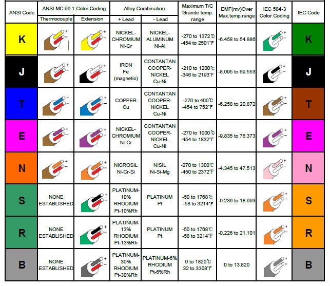
For convenience, base metal thermocouples are identified by letter, K, J, T, E, and N. Type K and J are the most widely used in industry. Base metal thermocouples are chosen for use based on emf output, temperature range, and the most often overlooked, environment. Base metal thermocouples are used in a wide range of industries including medical, diagnostics testing, vehicle engines, gas appliances such as boilers, water heaters, and ovens. They are widely used in the heat treat industry. Thermocouples are invaluable in monitoring and validating critical processes.
Type K Thermocouple
Type K thermocouples are nickel based so they work well in most applications. Type K thermocouples have good corrosion resistance. They’re inexpensive, accurate, reliable, and have wide temperature ranges. Maximum continuous temperature is 2012°F (1,100°C).
Advantages:
- Good for high temperature applications
- Appropriate for use in oxidizing or inert atmospheres at temperatures up to 2300°F (1260°C)
- Best in clean oxidizing atmospheres
Disadvantages:
- Not recommended for use under vacuum or partially oxidizing atmospheres
- Not for use in sulfurous atmospheres unless protected
- Not recommended in a vacuum at high temperatures
Type J Thermocouple
Type J thermocouples consist of a positive leg of iron and a negative leg of copper nickel alloy. They have smaller temperature ranges and shorter lifespans at higher temperatures than the Type K. They are equivalent to the Type K in terms of expense and reliability. It is a good choice for general purpose applications.
Advantages:
- Relatively high thermoelectric power
- Appropriate for use in vacuum, air, reducing, or oxidizing atmospheres
Disadvantages:
- The Iron leg is susceptible to oxidation
- Should not be used in sulfurous atmospheres
- Iron leg limited at subzero use due to rusting and embrittlement
Type T Thermocouple
Type T are very stable thermocouples and are often used in extremely low temperature applications such as cryogenics. They are found in other laboratory environments as well. The type T has excellent repeatability between –380°F to 392°F (–200°C to 200°C)
Advantages:
- Very stable
- Moisture resistant
- Useful to 700°F (370°C)
- Can be used in vacuum, reducing, or inert atmospheres
Disadvantages:
- Lower temperature range
Type E Thermocouple
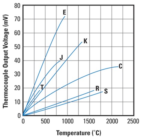
Type E are nickel-chromium versus copper-nickel thermocouple alloy combinations that produce the highest emf per degree of any of the base metal thermocouple alloy combinations. Type E can be used in temperatures from 300°F to 1600°F (149°C to 871°C).
Advantages:
- Good in oxidizing atmospheres
- Higher temperature range than type J
- More stable than type K
- Has the highest output EMF of any standard type
Disadvantages:
- Vulnerable to sulfur attack
- Only short-term use in a vacuum
- Only short-term use under partially oxidizing conditions.
- Only short-term use in alternating cycles of oxidation and reducing atmospheres
Type N Thermocouple
Type N thermocouple alloys are nickel based. Type N shares the same accuracy and temperature limits as the Type K. Type N has better repeatability between 572°F to 932°F (300°C to 500°C) compared to the type K.
Advantages:
- Good in oxidizing or inert atmospheres
- Less aging as compared to Type K
- Better suited for nuclear environment
Disadvantages:
- Do not use in sulfurous atmospheres
- Slightly more costly than Type K
Questions to Ask When Choosing Thermocouples
Besides the metallurgy of the thermocouple, consideration needs to be given to the style of sensor, probe or wire, and construction of the wire that carries the signal from the sensor to the instrument reading the signal. The purpose of the sensor is to achieve the same temperature as the process it is measuring and relay that temperature to the process instrumentation. The process being measured should dictate the type of sensor. If the process would in some way damage the sensor or invalidate its accuracy through corrosion, flow, pressure, or another condition, then a probe style sensor would be best. If the temperature being measured is in a static environment like a paint booth in an automotive assembly plant, an engine and exhaust system on a test stand, heat treating oven, or even a fluid that is not flowing, then a wire style sensor should work. The wires can even be tack welded in smelting or forging operations in one-time use applications.
Thermocouple Wire
Thermocouple wire construction or design has many factors to consider. These factors include accuracy, resistance to heat, abrasion, moisture and chemicals, flexibility, and durability as well as size constraints Accuracy falls into two classifications, Standard Limits of Error and Special Limits of Error. Special Limits of Error wire or conductor shares the same metallurgy with Standard Limits of Error but has better accuracy as the name implies. Standard Limits of Error wire or conductor would have a wider understood range of inaccuracy. A quick rule of thumb for understanding the accuracy divergence between special and standard limits of error; special limits of error tolerance ±2.0°F (±1.1°C) up to 500°F (260°C) and then 0.4% beyond 500°F (260°C). As an example, the tolerance for a special limit thermocouple at 1000°F would be ±4.0°F (±2.2°C) (1000 X .004). For a standard limit thermocouple, the quick rule of thumb is ±4.0°F (±2.2°C) up to 500°F (260°C) and then 0.8% beyond 500°F (260°C). Using the same example, the tolerance at 1000°F (538°C) for a standard limit thermocouple would be ±8.0°F (±4.4°C) (1000 X .008).
Extension grade is a third class or grade of wire that should also be mentioned. Extension grade wire should not be confused with either of the thermocouple grade wires mentioned previously. Extension Grade wire in fact should not really be considered a thermocouple grade wire, but rather a signal wire that carries the signal of the temperature being measured by the sensor to the process instrumentation. Typically, extension grade wire is not exposed to the same conditions that the probe and thermocouple wire would be. It is usually removed at a distance from the process being monitored, and as such, the requirements for the construction of the extension grade wire are not as stringent. For instance, the heat resistance requirement for the insulation would not be as high or critical. The maximum temperature extension grade wire is certified to is 392°F (200°C).
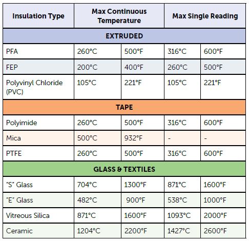
The choice of insulation is a critical factor in thermocouple wire design. Selection of insulation is influenced greatly by the atmosphere in which the wire will be operating. In the case of extension grade wires, the conditions will not be very demanding, for the most part, so PVC is a commonly used insulation. It has sufficient heat resistance for most environments, although not to the maximum certification temperature extension grade wire of 392°F (200°C), and has adequate moisture, chemical and abrasion resistance as well as flexibility. PVC is also an economical choice for insulation.
However, in many instances especially as the distance to the sensor and process temperature being monitored decreases, PVC does not have the properties necessary to withstand the conditions of those environments. This is particularly true of heat resistance with PVC being rated to 221°F (105°C ) only. Other insulations offer much higher heat resistance with the additional benefits of abrasion, moisture and chemical resistance if required. These other insulations can be broken down into 4 categories. Those categories are: extruded insulating compound, tapes, fiberglass, and high temperature textiles. Common extruded higher heat resistant extruded insulations would be fluoropolymer compounds like FEP and PFA. Heat resistance of these compounds range from 392°F to 500°F (200°C to 260°C). They exhibit excellent abrasion, moisture, and chemical resistance as well. They are also cost-effective solutions within their functional temperature ranges. Wires using fluoropolymer compounds for insulation are many times chosen for their smaller overall size.
Tapes most often used for insulating thermocouple wires are polyimide, PTFE, and Mica. They are normally chosen for higher heat resistance requirements. In the case of polyimide tape, it would be chosen when a lighter weight wire is desired. A desirable feature of PTFE tape is that it is a thermoset. Depending upon the tape, heat resistance is rated at 500°F (260°C) for polyimide and PTFE to 932°F (500°C) for the mica insulation. The polyimide tape has good abrasion, moisture and chemical resistance as does the PTFE. Mica is usually used to supplement PTFE and fiberglass insulations in dual insulation wire constructions. Flexibility of the wire is reduced with the use of mica tape. The overall dimensions of tape insulated wires are like wires with extruded insulation, except for mica taped wires as the mica tape increases the wall thickness of the wire.
If higher heat resistance is required, then the next logical insulation is fiberglass. Fiberglass insulation can be braided on the individual conductors, then braided again over both conductors to form the overall jacket; or the individual conductors can have fiberglass spiral wound, or ‘served’, around them with a braided overall jacket over both. This determination in construction is usually dependent on the gauge of the wire and the limitations of the braiding equipment.
The two types of glass encountered are E glass and S glass. E glass is rated for 900°F (482°C) and S glass for 1300°F (704°C). Glass insulated wires will have slightly larger walls than extruded, and tape insulated wires yield slightly larger overall diameters. While giving the user higher heat resistance than extruded or taped insulations, glass sacrifices some abrasion, moisture, chemical resistance and possibly some flexibility depending upon the wire gauge. Glass is seen in the automotive world because of the higher temperature requirements for component testing.
For more demanding heat resistance applications, there are the high temperature resistant textile insulations. These would be vitreous silica and ceramic fibers. Ratings for these insulations are 1600°F (871°C) for vitreous silica and 2200°F (1204°C) for ceramic. These insulations are also applied to wires on braiding equipment. These textiles produce a heavier wall than any of the other insulations previously mentioned so wires constructed with materials will have larger overall dimensions as well. Additionally, the insulations would be considered somewhat fragile and would lack abrasion resistance so they would best be used in a static environment. Applications requiring moisture or chemical resistance would not be recommended for these.
There are other options for thermocouple wire construction available including the gauge of the conductors, whether solid or stranded, shielding, drain wires, twisting, cabling, custom color coding or even applying a metal overbraid such as stainless steel or Inconel. While there are many constructions that are considered standard, not all applications are the same and there may be multiple processes with a facility requiring different types of sensors and wires. Given the critical nature of temperature in many manufacturing processes and testing scenarios, it is important that the data is gathered accurately, reliably and consistently to be relayed to the process instrumentation where the validity of the results can be trusted. It is best to consider as many factors and requirements as are known then consult with a manufacturer for the sensor and wires that would be best for the different processes being monitored.
About the Authors: John Niggle has been the business development manager at Pelican Wire since 2013 and has prior sales experience in process instrumentation. Ed Valykeo, a 40-year veteran in the wire industry, many with Hoskins, is a thermocouple specialist who has worked with Pelican for 10 years.
For more information, contact John or Ed at sales@pelicanwire.com or 239-597-8555.
Read more: Click here to read about international thermocouple codes from one of Heat Treat Today's editorial contributors.


