![]() What is the most common cause of induction tooling failures? What is essential for the longevity of induction tooling? What is a vital component for induction tooling’s successful performance? This informative article shares the answers to these questions and provides valuable guidance for your induction needs.
What is the most common cause of induction tooling failures? What is essential for the longevity of induction tooling? What is a vital component for induction tooling’s successful performance? This informative article shares the answers to these questions and provides valuable guidance for your induction needs.
This Technical Tuesday is provided by David Lynch, vice president of Engineering at Induction Tooling, Inc. and was featured in the Heat Treat Today’s 2021 May Induction print edition. Check out more original content articles in this digital edition or other editions here.

Vice President, Engineering
Induction Tooling, Inc.
Most induction heat treating applications are challenged with a harsh environment often dealing with high frequencies, high power, heat, smoke, steam, dirt, oil, quench fluid, quench additives, and contaminates. How induction tooling components are maintained in these harsh environments greatly impacts their performance and longevity.
The induction power supply, workstation, and material handling system should all be properly grounded. The work holding system should be level, square, and have proper alignment between the inductor coil and the workpiece for it to be heat treated. Part-holding fixtures should be held to a dimensional tolerance to ensure proper positioning and repeatability with minimal runout. The heat-treating process should include documentation of parameters including positioning (the air gap of the inductor coil relative to the workpiece), scan rates (in/sec), power (kw), frequency (kHz), heat time (sec), dwell time (sec), and quench time (sec). If auxiliary quench lines or nozzles are used, recording positioning data with pictures will guarantee repeatability of the process. Keeping track of quench water temperature, pressure, and flow along with percentage of polymer (aka viscosity) will help ensure consistent results. Keeping track of cooling water temperature, pressure, and flow is important in troubleshooting water cooling issues. The power supply should be routinely serviced and calibrated along with having an active preventative maintenance schedule.
Inductor coils should be properly designed to not only produce a heat treat specification, but also be of high quality, manufactured from quality materials with maximized water cooling and robust construction. Flux intensifiers should be properly matched to the operating frequency and attached to the inductor coil securely. Teflon insulators should be virgin grade and replaced if damaged or worn. Fasteners, fittings, and hose clamps should be non-ferrous such as brass or 300 series stainless steel. Hoses should be specified non-conductive and rated to meet or exceed supplied water pressure. Epoxies used should be rated for high temperatures and allow for expansion and contraction. Electrical contacts should be silver plated to provide superior contact and prevent oxidation.
Manufacturing inductor coils is a skill that takes years to develop and several more to master. These tools can be made from copper tubing utilizing fabrication techniques with the use of bending fixtures and forming dies. Most tools today are machined from solid, raw materials often with complex geometries. To ensure quality and consistency, 5-axis CNC machining is often used. Thirty to forty percent silver braze should be used for joining the inductor coil components and sealing water-cooling passages. Designs should avoid sharp corners and provide smooth transitions for optimal current flow and minimal stress risers. Computer-solid models, engineering drawings, and process forms following ISO 9001:2015 certified standards guarantee a quality manufactured induction coil.
Inductor coils are precision handmade tools and should be treated as such. Inductor coils should be supplied in a heavy-duty case with packing materials to provide the proper support and protection during shipping and storage. Identification should be clearly marked on the case. Many cases are lockable as theft may be a concern. When inductor coils are removed from service, they should be cleaned with soap and water using a Scotch-BriteTM cleaning pad. Steel wool and steel bristle brushes should be avoided as the steel can imbed into the copper and may cause more harm than good. Once the inductor is cleaned, it should be closely evaluated for signs of wear or damage. If there are any signs of wear or damage, it should be sent out for maintenance or repair so it will be ready for the next use. After tools are cleaned and evaluated, cooling passages should be blown out with air and the inductor should be dry before sealed in the case and put into inventory. Notes and pertinent data related to the inductor can also be stored with it such as the number of parts processed, any modifications made to the inductor coil, and recorded setup data.
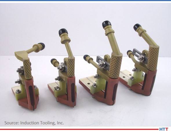
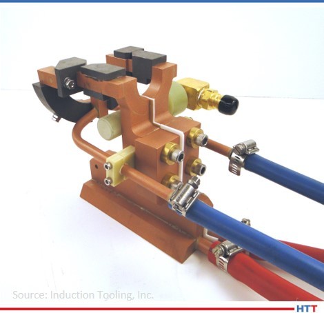
All of what was stated above about design and manufacture of inductor coils also applies to bus bars and quick-change adapters. These devices are used between the workstation and the inductor coil to bridge the gap closer to the workpiece. Originally developed for the automotive industry, quick-change adapters can drastically reduce changeover time, often without the use of hand tools. Since these devices are typically kept on the machine for long periods of time, it is important to check the condition and perform maintenance when needed. Scheduled maintenance of removal and cleaning of these devices will exceedingly increase their life. As with inductor coils, soap, water and a Scotch-BriteTM cleaning pad is all that is needed for these items; steel wool and steel bristle brushes should be avoided.
When installing bus bars, adapters, and inductor coils with a bolted contact, it is extremely important to make sure that each of the mating surfaces are clean and free from debris. When dirt accumulates or ferrous debris is contained between the contacts, severe arcing and melting can occur.
It is also very important to use proper fasteners. For correctly fastening contact surfaces, 300 series stainless steel bolts with heavy brass washers are preferred. The heavy brass washers help distribute the load evenly and help prevent damaging the copper. The bolt threads should be inspected for wear and replaced new if there is any sign of wear or damage. It is also very important to verify that the length of the bolts will properly clamp without bottoming out before tightened. The recommended torque procedure for 3/8-16 stainless steel bolts is to tighten each bolt twice at 35 to 40-foot pounds. Special "break-away" bolts are available that are designed to fail beneath the washer if they are over tightened. This prevents damage to the threaded insert inside the copper contact. The remainder of the bolt can then be removed with pliers. This is much easier and less expensive than having to repair a bus bar contact or workstation transformer.
The workstation contacts, bus bars, adapters, and inductor coils are all electrical components that when energized are a live circuit, often with high power. The inductor coil produces a strong magnetic field used to heat the workpiece. There are also stray magnetic fields in the surrounding area. It is very important that everything in the surrounding area of these components be non-ferrous to prevent them from heating up. Something as simple as a steel hose clamp in close proximity to the magnetic field could heat up, causing a hose to melt, or a hose to come off, preventing water cooling and severely damaging the induction tooling or the induction machine. Steel fittings can rust and contaminate a water system very rapidly, choking the water flow internally and causing premature failure from low water flow. Any support structure to the induction tooling components should be a quality non-porous insulating material. Non-porous materials prevent liquid and contaminates from being absorbed and ultimately may cause a short circuit.
Proper water cooling is essential to the performance and longevity of tooling components. Both the induction power supply components and induction tooling components need to be properly cooled. Most power supply manufactures have a closed loop cooling system requiring deionized or distilled water. Most power supply manufacturers require that the cooling water temperature be maintained from 80 to 90 degrees Fahrenheit to prevent condensation inside the cabinet and on the circuitry. For cooling the inductor coil, bus bars, and adapters, deionized or distilled water is not necessary. Cooling water for these induction tooling components is best to be kept below 70 degrees Fahrenheit. This may require a separate cooling supply. Through laboratory experimentation and real-world production trials, it has been proven that lower cooling water temperatures can drastically increase the life of these components, especially in high volume, high power, short cycle applications.
The internal water-cooling passages of the inductor coil can play a significant factor in performance and longevity. Each inductor design should focus on maximizing water flow while minimizing sharp transitions.
The cooling water supply should come from a clean water source with a filtration unit of 25 microns placed just before it enters the induction tooling components. This guarantees that contaminates are filtered out, which may otherwise cause a low-flow or no-flow condition.
Quality non-ferrous fittings should be properly sized and configured to ensure the hoses are attached correctly to the induction tooling. It is very common to see 3/8" quick-change fittings used for cooling lines and 1/2" or 3/4" quick-change fittings used for quench lines. Using quick-change sockets for supply lines and quick-change plugs for return lines ensures the proper connections are made every time. Color-coding the hoses also helps in identifying water lines. It is very common to see blue hose for supply lines, red hose for return lines, and black hose for quench lines.
Some inductor coils can be very small, having very limited water-cooling passages due to physical space. With these small inductors, it is even more important to have proper water cooling. In these situations, the use of a high-pressure booster pump may become necessary. These pumps can ensure cooling water continues to flow through these tight passages. Positive displacement pumps can also overcome steam pockets and help prevent vapor locks.
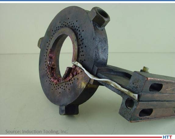
Problems with a cooling system can be detrimental to the performance and longevity of induction tooling components. Contamination in the cooling system can lead to low water flow. Problems with the water pump can also cause a low water flow condition. Then, low water flow can cause a steam vapor lock in the inductor coil leading to a rupture at a braze joint, a rupture through the tubing in a fabricated inductor coil, or a breach in the copper exposing the cooling chamber. Low water flow can also cause laminar flow internally which leads to thermal failure, resulting in exposed surface cracks through to the cooling chamber. Low water flow is sometimes identified by darkening of copper with purple color tones on the cooling return side of the inductor coil.

Induction tooling components cannot survive without water cooling. Symptoms include darkening of copper with purple color tones, melted copper, and catastrophic failure. Catastrophic failures caused by a no-water condition cannot be patched and require a major rebuild or replacement. It is a wise investment to have a flow indicator on the machine that prevents operation if there is no water flow or a low water flow condition.
All of what is stated earlier about the design and manufacture of inductor coils, bus bars, and adapters can also apply to quenches. These devices are used to evenly cool the part after heating to transform the structure consistently. Let’s discuss some of the important details in a quench system such as their design, fitting and hose requirements as well as pumps, filtration, and maintenance.
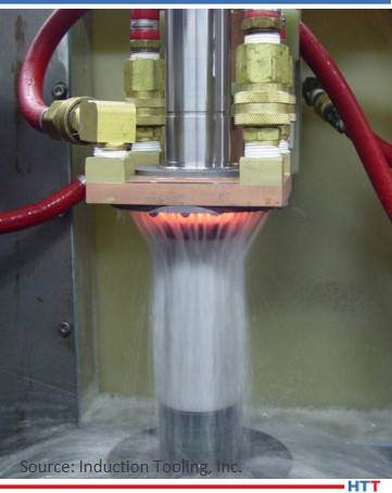
Quenches should be designed to provide a sufficient amount of quench to fully transform the metallurgical structure as specified. The quench pattern should be a uniform array of holes to quench the part at a proper impingement angle. The volume of water required should be matched with a supply having an inlet to outlet ratio not to exceed 1 in: 2 out. Hoses should be specified non-conductive and rated to meet or exceed supplied water pressure. Fittings should be high quality, non-ferrous without auto shutoffs, which can hinder quenching action and tend to clog more often.
Quenches can be a component that is kept on the machine for long periods of time. It is important to check the condition of these devices and perform routine maintenance. Scheduled maintenance of removal and cleaning these devices will exceedingly increase their life. Soap, water and a Scotch-BriteTM cleaning pad works well, and again, steel wool and steel bristle brushes should be avoided. Having a quench designed with bolted removable quench plates allows easy clean out.
Quench water needs to be filtered and contaminates kept at a minimum to improve performance and increase longevity of induction tooling components. A typical quench filter consists of a stainless-steel filter housing and a 100-microns bag filter. It is also very important to have a system for magnetic particle removal. Magnetic rod filters are available in many configurations, some that install inside the filter housing with the bag filter. Automatic separators are also often used. A low-cost alternative is to install a rubber coated magnet in the quench tank. In a non-ferrous tank, it can simply be dropped to the bottom. In a ferrous tank, it must be suspended to prevent the tank itself from becoming magnetized. All these methods can work, but only if they are properly maintained. A solid preventative maintenance schedule for these filters is essential.
When filters are not used or maintained, tooling repairs are required more frequently. Common contaminates found inside quenches include oil dry, metal chips, and chewing tabaco. We see inductor coils come in for rebuild with a heavy patina of dirty, crusty contaminates. These contaminates are commonly a buildup of magnetic particles attracted by the magnetic field generated by the inductor coil. This patina accumulates and can create a short circuit, damaging the inductor coil.
To summarize, contamination is by far the most common cause of induction tooling failures. Water cooling is essential for longevity of induction tooling. Maintenance is essential for the performance of induction tooling. High quality, well-designed, robust induction tooling should be used for best results and consistency. Analyze induction tooling failures when they occur. Troubleshoot induction tooling rebuilds for possible machine issues. Look for methods of improvement with each opportunity. In closing, the best way to improve the performance and longevity of induction tooling components is to have open and frequent lines of communication with your tooling vendor.
About the Author: David Lynch is vice president of engineering at Induction Tooling, Inc. with 36 years of experience and is also the Deputy of the ISO quality system. He has created and developed the system and templates being used today for creating and tracking engineering drawings, job history, rate tracking, and job performance. David holds several design patents, has authored several published articles, and has often presented at technical sessions. He enjoys working closely with customers to develop valued solutions across a wide range of induction heating applications from initial design concepts to implementation, customer support and troubleshooting.
For more information, Contact David at dlynch@inductiontooling.com.


