Dr. Valery Rudnev On . . .
Induction Hardening Tips: Equipment Selection for Scan Hardening
Introduction
Induction scan hardening is one of the more popular techniques for strengthening various steels, cast irons, and powder metallurgy components. This scanning method is be used to harden flat surfaces or irregular shapes (e.g., rails, bumpers, bed-ways, support beams, track shoes for earth moving machines, teeth of large gears, etc.); however, it is most frequently used for hardening outside and/or inside surfaces of cylindrically shaped components, such as shafts, pins, raceways, etc. In scan hardening, the inductor or workpiece or both moves linearly relative to each other during the hardening cycle.
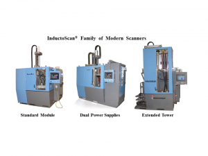
Depending on the workflow of parts, the induction system can be built as vertical, horizontal, or even at an angle, though vertical scan hardening is by far the most popular design. As an example, Figure 1 shows three variations of the InductoScan® family of modular vertical scan hardening systems.

What to Choose: Vertical Scanners vs. Horizontal Scanners
Both vertical and horizontal induction scanning systems are viable means to heat treat components. The decision of whether to use a vertical or horizontal scan hardening system is usually based upon the shape and length of heat treated parts, as well as the available space and a workflow throughout the plant or factory in which the equipment is to be installed. Horizontal hardening is often chosen when long workpieces are to be processed (typically 4ft/1.2m or longer) or when high production rates are needed for processing shorter parts.
Vertical scanners are typically associated with a smaller footprint. In the majority of applications, the cylinder-shaped workpiece (e.g., shafts) is positioned between centers or some other tooling or fixture. The workpiece may rotate inside the inductor to even out the hardening pattern around the circumference, or it may be located preferentially with respect to the inductor and processed without rotation when hardening workpieces of certain shapes. The quench spray typically impinges the part approximately 12mm (½”) to 40mm (1.5”) from the coil heating face and is angled away to prevent the quench from splashing back into the inductor. This dimension can vary with different types of steel, the scan rates, and the design specifics.
Setting Up Scan Hardening Systems
Vertical systems can be set up to process as many as four shafts at a time depending on the size of the shafts being processed and the available power source. Parts are loaded either manually or automatically onto a lower center. A loading assist “vee” block or nest may be used to steady the part as it is being loaded and processed. For larger parts, pneumatic cylinders lift the upper centers to facilitate loading. With vertical scan hardening, it may take an appreciable amount of time to process the workpiece because it must be loaded, scanned along the length up to the position where the heating process commences, fast scanned back down to the load-unload position, and then unloaded.
In contrast, a horizontal system is typically set up as a single continuous scanning line that allows parts to be loaded from a magazine and continuously fed to the exit of the machine. Depending on the specific heating requirements for the end of the component, parts are fed end-to-end through the heating coil and pass on to the next process. The loading system can push parts through the inductor by a pinch drive mechanism, conveyor, mechanical pushers, or other means, such as skewed rollers [1]. On a horizontal system, due to heavy duty roller support underneath, gravity, and any required stabilizing devices on top of the workpiece, the part is maintained in the center of the induction coil and quench ring. There is usually less risk of distortion than that which occurs with a vertical system where the part’s shape can change or warp if the part is not always centered.
However, during the heating process on a horizontal system, it may be more difficult to maintain the exact location of features of the part since it is commonly free rolling on the skewed rollers. For this reason, consideration should be given to a part’s shape, the symmetry of its positioning in respect to the heating coil, and selection of support devices. When horizontal systems are used for heat treating long parts of appreciable weight, it might be challenging to speed up or slow down the progress of the workpiece along the skewed rollers as quickly as might be done in vertical scanners with a servo-driven carriage that captures the part.
The roller system of horizontal scan hardeners can interfere with achieving symmetrical cooling of the workpiece since the location of the rollers and the rotation detection mechanism on shorter parts may be too close to the coil or quench barrel. Additionally, a stabilizing fixture may be required to prevent lighter and smaller workpieces from being moved axially by electromagnetic forces rather than the roller system. As with the vertical system, some type of rotation detection must be employed to ensure that the part is actually rotating as it is passing through the heating coil.
Quenching Challenges
Quenching presents a challenge with horizontal scanning [1]. When scanning vertically, quenching takes place below the inductor, which naturally allows gravity to pull the quench fluid down, therefore, the quench fluid continues to flow on the part long after it has passed the quench chamber, which is beneficial to achieving circumferential uniformity of quenching as well as reaching temperatures suitable for handling. When quenching horizontally, the effect of gravity is different and the way the quenchant falls from the workpiece varies leading to the probability of non-uniform cooling along the circumference of the heat-treated component (e.g., quenchant may run along the top of the part but fall off the bottom).
It is also more critical for horizontal scanners to maintain a sufficient distance between the inductor exit and the quenching device due to the higher probability of the liquid quenchant splashing back into the inductor. This could lead to irregular results caused by different cooling rates affecting the hardness consistency as well as the magnitude and distribution of residual stresses.
All of these factors can be summarized as follows:
- The main process differences between vertical or horizontal scan hardening systems lie in the part handling and quenching subtleties.
- With some scanners, splash shields, deflectors, and drip trays may be needed to prevent the backsplash of the quench fluids.
Maximizing Process Flexibility of Induction Scanners
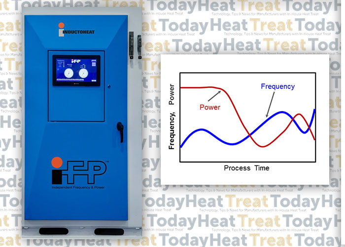
It is commonly assumed that all scan hardening systems exhibit high process flexibility with respect to the workpiece length and, to some extent, variations in the diameter of the part. Conventional scan hardening provides the ability to vary the speed and power during the process, which controls the amount of heat applied to different areas of the part. Recently developed Statipower-IFP® inverter technology (Figure 2) extends the capability of conventional induction hardening systems to instantly and independently adjust not only power and scan rate but also frequency (5kHz to 60kHz range) during scan hardening cycle [2].

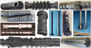
In the past, the flexibility of induction scanners was limited to using power supplies with single operational frequency. However, when processing a family of parts or components with numerous geometrical irregularities (including large diameter changes, multiple holes, sharp shoulders, combinations of solid and hollow areas, various required case depths, etc., see Figure 3), the fixed frequency in conventional induction scanners can be inadequate, producing “hot” and “cold” spots, as well as unwanted microstructures (e.g., local grain boundary liquation and grain coarsening).

Single frequency scanners have been used to tweak the process in an attempt to promote or suppress thermal conduction [1,2], resulting in a compromise in achieving the desired metallurgical quality, production rate, and process capability. In the heating stage, compromise affects the ability to provide heat-appropriate austenization, but it also presents challenges in the quenching stage.
Austenization is followed by a quenching stage (spray or immersion). If the available, fixed frequency of a conventionally designed induction scanner is considerably higher than optimal then the depth of heat it generates (current penetration depth) is smaller than needed, which might not be sufficient in establishing necessary austenization. In this case, to reach sufficient austenization, the scan rate and applied power must be reduced to allow thermal conduction to the required subsurface depth. Unfortunately, a noticeable heat surplus might still occur.
An Example of Compromised Results
As an example, Figure 4 shows the computer modeling results of the induction scan hardening of a hollow medium carbon steel shaft that has diameter changes, a chamfer, and a groove. Nominal outside diameter is 0.05m (2”); nominal inside diameter is 0.02m (3/4”). Because the shaft is symmetrical, only the top half was modeled. Temperature variations at four selected areas of the shaft are monitored at different inductor positions. Frequency was constant at 15 kHz.
The scan rate and coil power were varied during hardening as an attempt to accommodate changes in the shape of the shaft.
Figure 4. Dr. Valery Rudnev on Equipment Selection for Scan Hardening on Vimeo.
Reducing scan speed (in some cases substantially) not only adds unnecessary cycle time, but if the scan speed is too slow, certain regions of a heat-treated component may cool below the critical temperature before it enters the quench zone, resulting in an undesirable formation of mixed structures and upper transformation products, as well as reduced or spotty hardness readings.
If the fixed frequency of a conventionally designed scanner is noticeably lower than optimal, it may produce a deeper than required austenized layer, affecting hardness depth, transition zone and creating excessive distortion. In this case, increasing scan rate and power density should minimize, but not eliminate, this outcome. Such a compromise can still affect local spray quenching producing undesirable metallurgical results.
Conclusion
It is important to remember that applied frequency has the greatest impact on depth of induction heat generation. A new generation of Statipower-IFP® inverters (Figure 2) eliminates these drawbacks by optimizing the metallurgical quality of induction scan hardening, expanding process flexibility and maximizing a production rate. This patented technology can be effectively used in both vertical and horizontal induction scanners. Reports [2] show changing both coil power and frequency during scan hardening can reduce peak temperatures on 70oC (125oF) while maintaining the required hardness pattern.
I recommend Reference #1 to readers interested in further discussion on induction scan hardening subtleties.
References
- Rudnev, D.Loveless, R.Cook, Handbook of Induction Heating, 2nd Edition, CRC Press, 2017.
- Doyon, V.Rudnev, C.Russell, J.Maher, Revolution-not evaluation-necessary to advance induction heat treating, Advance Materials & Processes, September 2017, p.72-80.
______________________________________________
Dr. Valery Rudnev, FASM, is the Director of Science & Technology, Inductoheat Inc., and a co-author of Handbook of Induction Heating (2nd ed.), along with Don Loveless and Raymond L. Cook. The Handbook of Induction Heating, 2nd ed., is published by CRC Press. For more information click here.


