This is the third in a 4-part series by Dr. Steve Offley (“Dr. O”) on the technical challenges of monitoring low-pressure carburizing (LPC) furnaces. The previous articles explained the LPC process and explored general monitoring needs and challenges (part 1) and the use of data loggers in thru-process temperature monitoring (part 2). In this segment, Dr. O discusses the thermal barrier with a detailed overview of the thermal barrier design for both LPC with gas or oil quench. You can find Part 1 here and Part 2 here.
Low-Pressure Carburizing (LPC) with High-Pressure Gas Quench – the Design Challenge
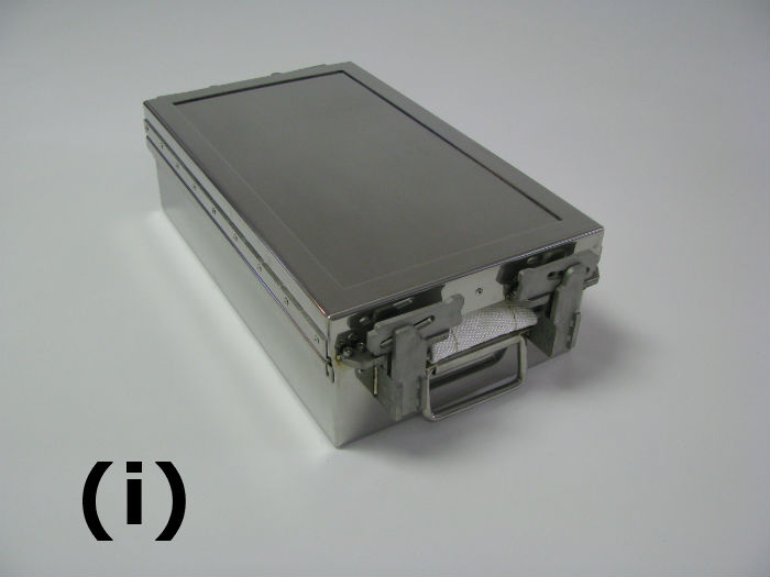
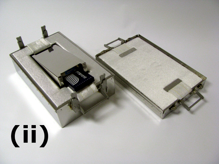
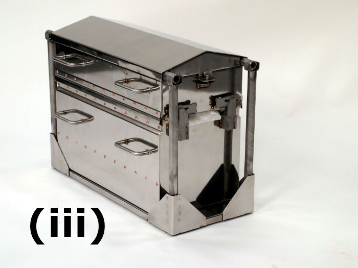
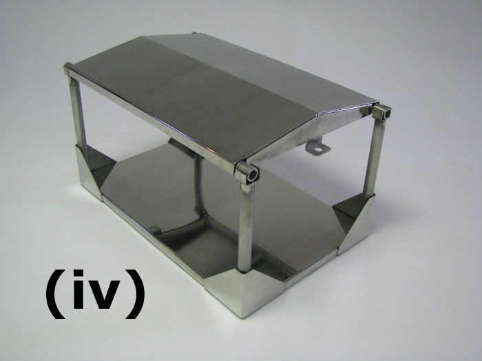
A range of thermal barriers is available to cover the different carburizing process specifications. As shown in Figure 1 the performance needs to be matched to temperature, pressure and obviously space limitations in the LPC chamber.
Fig 1: Thermal Barrier Designed Specifically for LPC with Gas Quench.
(i) TS02-130 low height barrier designed for space limiting LPC furnaces with low-performance gas quenches (<1 bar). Only 130 mm/5.1-inch high so ideal for small parts. Available with Quench Deflector kit. (0.9 hours at 1740°F/950°C).
(ii) Open barrier showing PTM1220 logger installed within phase change heatsink.
(iii) TS02-350 High-Performance LPC barrier fitted with quench deflector capable of withstanding 20 bar N2 quench. (350 mm/13.8-inch WOQD 4.5 hours at 1740°F /950°C).
(iv) Quench Deflect Kit showing that lid supported on its own support legs so pressure not applied to barrier lid.
The barrier design is made to allow robust operation run after run, where conditions are demanding in terms of material warpage.
Some of the key design features are listed below.
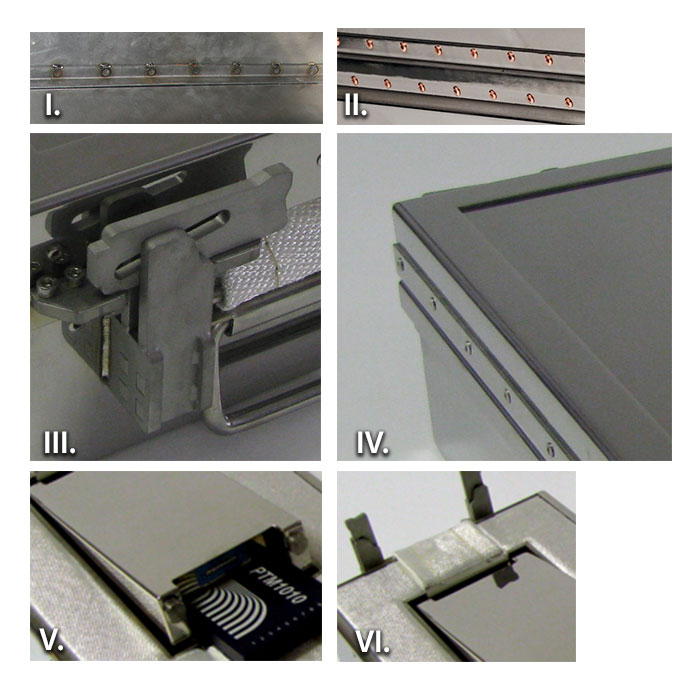
I. Barrier – Reinforced 310 SS strengthened and reinforced at critical points to minimize distortion (>1000°C / 1832°F HT or ultra HT microporous insulation to reduce shrinkage issues)
II. Close-pitched Cu-plated rivets (less carbon pick up) reducing barrier wall warpage
III. High-temperature heavy duty robust and distortion resistant catches. No thread seizure issue.
IV. Barrier lid expansion plate reduces distortion from rapid temperature changes.
V. Phase change heat sink providing additional thermal protection in barrier cavity.
VI. Dual probe exits for 20 probes with replaceable wear strips. (low-cost maintenance)
LPC or Continuous Carburizing with Oil Quench – the Design Challenge
Although commonly used in carburizing, oil quenches have historically been impossible to monitor. In most situations, monitoring equipment has been necessarily removed from the process between carburizing and quenching steps to prevent equipment damage and potential process safety issues. As the quench is a critical part of the complete carburizing process, many companies have longed for a means by which they can monitor and control their quench hardening process. Such information is critical to avoid part distortion and allow full optimization of hardening operation.
When designing a quench system (thermal barrier) the following important considerations need to be taken into account.
- Data logger must be safe working temperature and dry (oil-free) throughout the process.
- The internal pressure of the sealed system needs to be minimized.
- The complexity of the operation and any distortion needs to be minimized.
- Cost per trial has to be realistic to make it a viable proposition.
To address the challenges of the oil quench, PhoenixTM developed a radical new barrier design concept summarized in Figure 2 below. This design has successfully been applied to many different oil quench processes providing protection through the complete carburizing furnace, oil quench and part wash cycles.
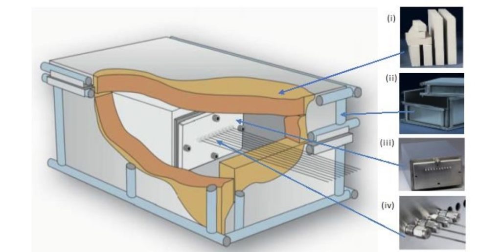
(i) Sacrificial replaceable insulation block replaced each run.
(ii) Robust outer structural frame keeping insulation and inner barrier secure.
(iii) Internal completely sealed thermal barrier.
(iv) Thermocouples exit through water/oil tight compression fittings.
In the next and final installment in this series, Dr. O will address AMS2750E and CQI-9 Temperature Uniformity Surveys, which often prove to be challenging for many heat treaters. "To achieve this accreditation, Furnace Temperature Uniformity Surveys (TUS) must be performed at regular intervals to prove that the furnace set-point temperatures are both accurate and stable over the working volume of the furnace. Historically the furnace survey has been performed with great difficulty trailing thermocouples into the heat zone. Although possible in a batch process when considering a semi-batch or continuous process this is a significant technical challenge with considerable compromises." Stay tuned for the next article in the series of Temperature Monitoring and Surveying Solutions for Carburizing Auto Components.


