Aerospace Heat Treating

The Future of Vacuum Oil Quenching

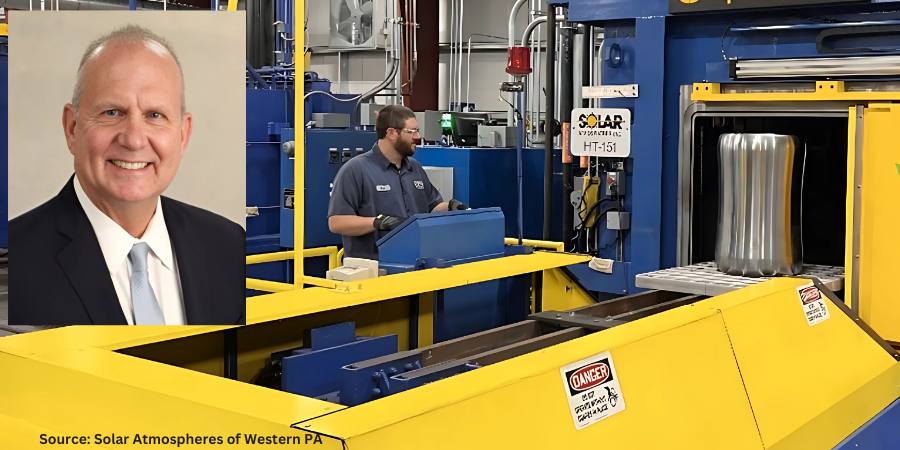
Despite years of research and development that resulted in several important technological innovations, the constraints of high-pressure gas quenching are ever more evident. In today’s Technical Tuesday, Robert Hill, FASM president of Solar Atmospheres of Western PA, addresses the creation of a new, robust style of vacuum oil quench furnace. The results challenge the schematics in how the next generation of oil quench furnaces should be designed, built, and operated.

This informative piece was first released in Heat Treat Today’s November 2024 Vacuum print edition.


Introduction

After decades of research and development that resulted in several important technological innovations, the constraints of high-pressure gas quenching are ever more evident. Gas cooling runs into efficacy issues when compared to liquid quenchant cooling, chiefly for heavier cross sections. This stays true even when using specialized inert gas blends and heightened gas pressures.

Additionally, it is undeniable that stringent liquid quench Aerospace Material Specifications (AMS) standards for certain aerospace alloy steels will never change. In fact, many industry standards (e.g., SAE/AMS and U.S. defense standards) and client specifications often mandate oil quenching of alloys or component parts.

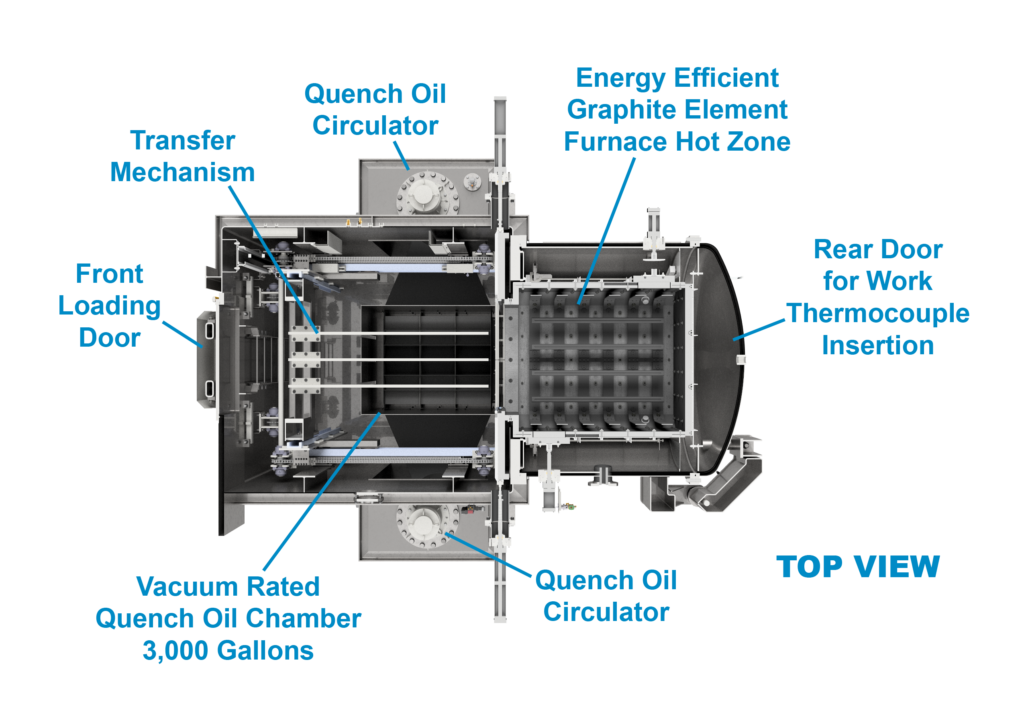
To meet the demand for an effective, sustainable liquid quench solution, Solar Manufacturing with Solar Atmospheres engineers worked through the tumultuous period of the pandemic to create a new, robust style of vacuum oil quench furnace. Their work culminated in a vacuum oil quench furnace with a 36″ x 36″ x 48″ hot zone that operates up to 2000°F and can accommodate a weight capacity of 2000 lbs. With high uptime reliability and excellent metallurgical results, the NEO™ represents a paradigm shift in how the next generation of oil quench furnaces should be designed, built, and operated.

Rigorous Design for Metallurgical Excellence

The next generation of oil quench furnaces heralds an era of metallurgical excellence. This is made apparent across three key measures: control over surface contamination, prevention of parts cracking, and flexible processing of dissimilar materials.

No Surface Contamination

Figure 2. Loading in the NEO furnace
Source: Solar Atmospheres of Western PA

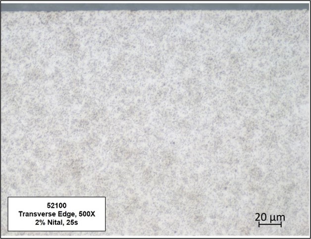
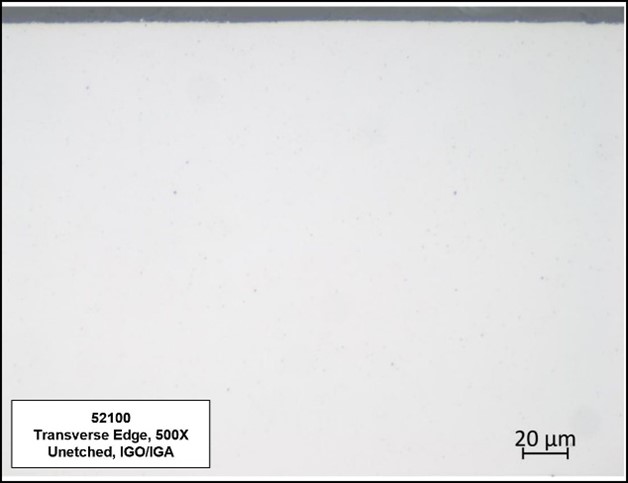
By implementing a vacuum design to the oil quench furnace, the research team avoided issues faced by traditional atmosphere oil quench furnaces, such as surface contamination and intergranular oxidation/intergranular attack (IGO/IGA). Additionally, they meticulously addressed design concerns regarding oil backstreaming in the new multichambered vacuum system. After two years of usage, the hot zone has remained pristine and oil-free.

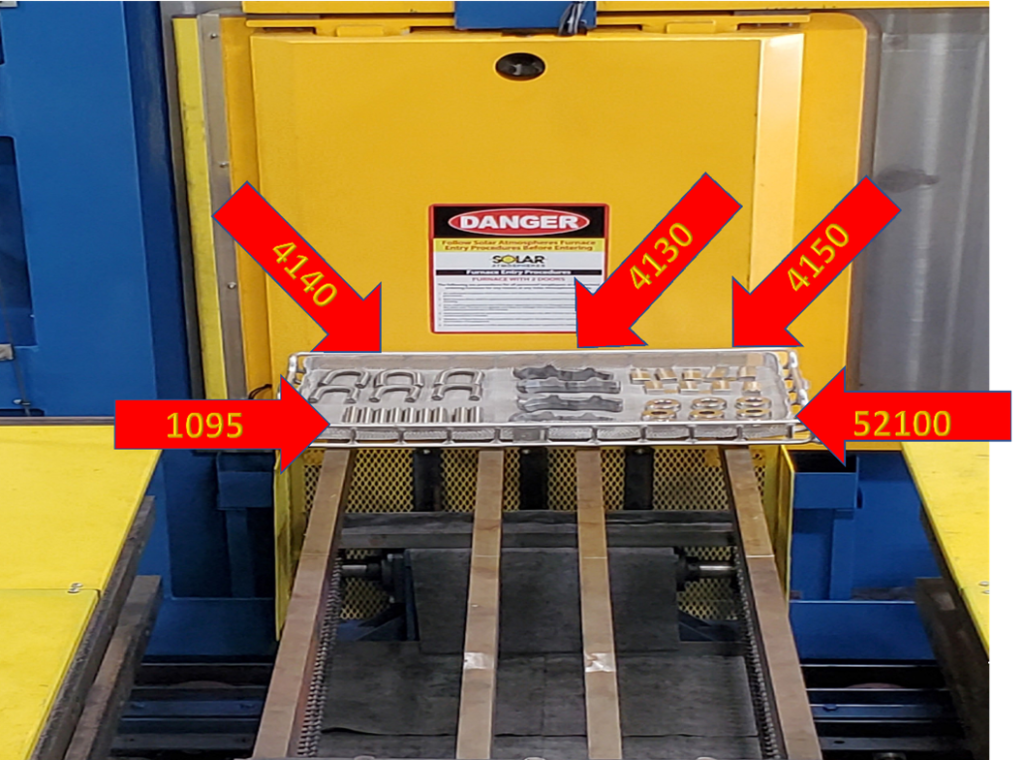
By effectively removing the possibility of any surface contamination, both IGO and decarburized or carburized surfaces on oil quenched components are eliminated. These critical metallurgical features are unattainable in traditional gas-fired Endothermic batch furnace equipment.

Precision Prevents Part Cracking

To eliminate the potential of part cracking, quench oil temperatures should be able to be maintained between 140°F to 180°F ±5°F, which enhances consistent and repeatable metallurgical results. Furthermore, having the furnace designed so that quench oil recirculates within a closed loop oil to air cooling system keeps water contamination from infiltrating the oil.

No Carbon Content Matching

The next generation of vacuum oil quench furnaces should also have highly controllable atmospheres, devoid of oxygen, which will remove the need to mechanism, which has demonstrated flawless performance for over two years.

Additionally, it is imperative that these furnaces be capable of using more conventional quench oil. A good quench needs excellent vapor pressure, powerful enough to allow the oil to vaporize. Furnaces can be designed with this in mind, allowing operators to save costs by using more conventional quench oils. For example, after rigorous laboratory experimentation into the vaporization of various quench oils at different pressures and temperatures, it was decided to purchase 3000 gallons of Houghton G quench oil, versus the “vacuum only” quench oils that are currently on the market today.

Figure 3. A display of a variety of parts which can be processed in the same run
Source: Solar Atmospheres of Western PA

The next generation of oil quench furnaces should also finally provide metallurgical and quality engineers the ability to thermocouple the oil quenched parts in accordance with AMS2750 Rev H standards. Being able to monitor part temperature with up to twelve (12) data points, as defined by the latest AMS2750 revision, ensures thorough and precise thermocouple monitoring, bolstering control and repeatability.

Lastly, in a hermetically sealed furnace, another layer of control should be established through installing an internal camera. With “eyes” into the furnace, the operator will be able to watch the load transfer in real time from a control panel.

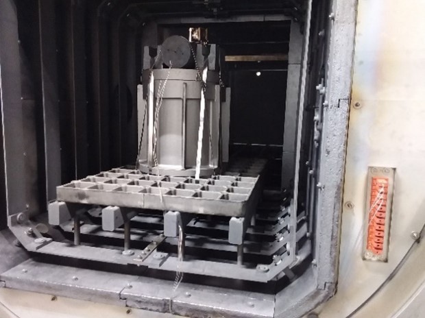
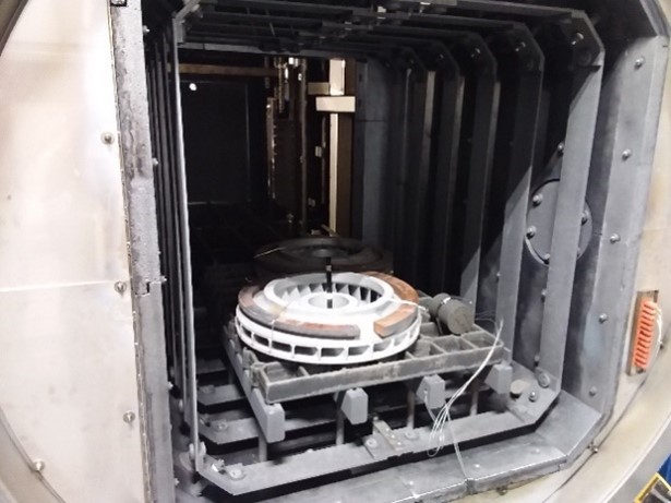
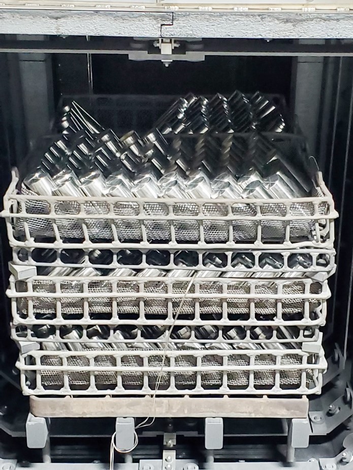
These operational attributes are on full display in the example of an automated austenitized cycle: At the completion of the cycle, the specially-designed transfer mechanism delivers precisely heated parts from the hot zone to the 3000-gallon oil quench chamber consistently within 20 seconds — all without the expulsion of flames and the discharge of smoke.

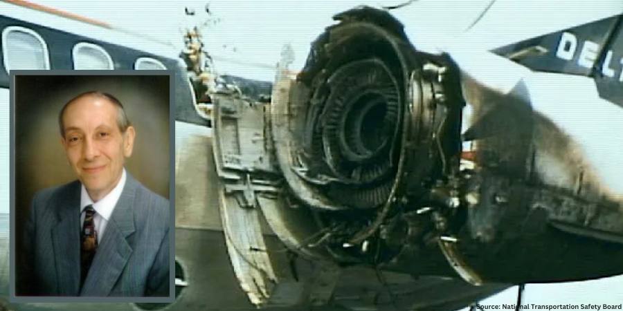
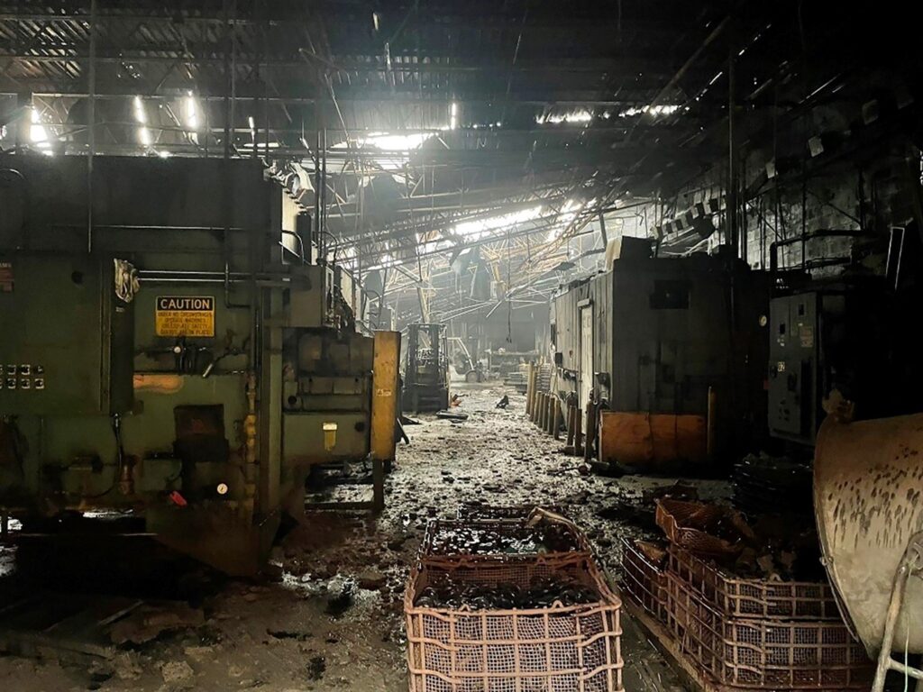
Oil flames and smoke are no longer acceptable realities in heat treatment operations. Unfortunately, the heat treating industry has been misled in the belief that a catastrophic disaster will never happen to them. There have been multiple “total losses,” mostly due to oil quench fires and explosions. Recently, it is well known that if an insurance adjuster sights a flame or smoke within a plant, they are reluctant or may even refuse to write the policy.

Vacuum furnaces offer a safe, contained alternative to the harmful open emissions and dangerous working conditions. For operations where the safety and the well being of the workforce are paramount, vacuum furnaces eliminate the risks associated with open flame exposure, explosivity, and skin burns.

Yet the next generation of vacuum oil quench furnaces should also open at both ends at the end of a cycle to expose it to atmosphere. Full air exchange mitigates the potential hazards of confined spaces.

Figure 5. Top view showing innovative design features for the next generation of vacuum oil quench furnaces
Source: Solar Atmospheres of Western PA

Meeting Environmental Demands

With ever more stringent environmental regulations, the next generation of vacuum oil quench furnaces will play a pivotal role in reducing the carbon footprint of the heat treating industry. It has been estimated that 80% of fuel used for heat treatment could be replaced by electricity, thus drastically reducing CO2 emissions: “When you burn something that contains carbon, you get carbon dioxide that you either must take care of or release into the atmosphere. With electric heating, you do not have any exhaust.”

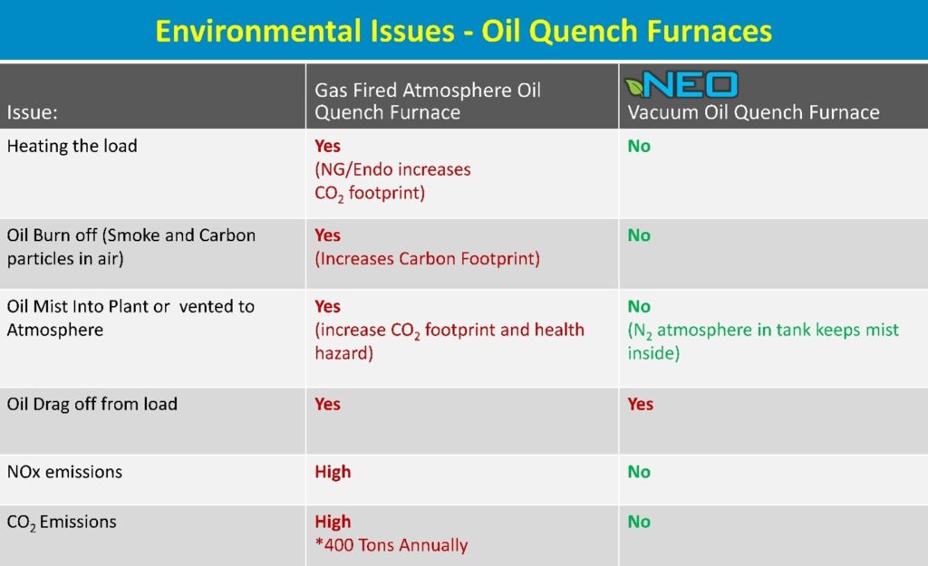
The second column in the chart on page 30 addresses the multiple environmental concerns associated with traditional batch IQ gas-fired oil quenching furnaces. The third column outlines the advantages of the design for the next generation of oil quench furnaces, which embraces electric heating as a sustainable alternative to fossil fuels. As sustainability pressures continue to mount, governments, clients, and primes alike will continue to flow down requirements on how heat treaters plan to reduce their carbon footprints.

Figure 6. Safety hazards in operating atmosphere furnaces
Source: The Monty

Conclusion

As the demands for metallurgical precision, safety, and environmental sustainability continue to mount, Solar’s new vacuum oil quench furnace emerges as a representative of the next generation of vacuum oil quenching technology. Characterized by unparalleled efficiency, precision, and sustainability, such furnaces will continue to lead the industry toward a future defined by cleanliness, safety, and environmental stewardship.

Table 1. Data from the AICHELIN Group
Source: Solar Atmospheres of Western PA

References

Kanthal, “Heat Treatment CO2 Emissions cut by 50 percent by using electricity” (April 2019), https://www.kanthal.com/en/knowledge-hub/inspiring-stories/heat-treatment-co2-emissions-cut-by-50-percent-by-using-electricity/.

Aichelin Group, “CO2 Footprints and the Heat Treat Industry,” The Monty (January 2024).

About the Author:

Robert Hill, FASM
President
Solar Atmospheres of Western PA

Robert Hill, FASM, began his career with Solar Atmospheres in 1995 at the headquarters plant in Souderton, PA. In 2000, Hill was assigned the responsibility of starting the second plant in Hermitage, PA, where he has specialized in the development of large furnace technology and titanium processing capabilities. Additionally, he was awarded the prestigious Titanium Achievement Award in 2009 by the International Titanium Association.

For more information: Contact Robert at bob@solaratm.com


The Future of Vacuum Oil Quenching Read More »

Ask the Heat Treat Doctor®: How Do Parts Fail?

The Heat Treat Doctor® has returned to offer sage advice to Heat Treat Today readers and to answer your questions about heat treating, brazing, sintering, and other types of thermal treatments as well as questions on metallurgy, equipment, and process-related issues.


Product failures (Figure 1) can often be traced to deficiencies in design, materials, manufacturing, quality, maintenance, service-related factors, and human error to name a few. Examples of failures include misalignment, buckling, excessive distortion, cracking, fracture, creep, fatigue, shock, wear, corrosion, and literally hundreds of other mechanisms. Let’s learn more. 

Figure 1. Image of damage to left fuselage and engine; fire damage to nacelle.
Source: National Transportation Safety Board
Figure 2.: Model of material science depicting— key interactions and /interrelationships
Source: The HERRING GROUP, Inc.

Whatever the source, it is important to recognize that it is next to impossible to separate the product from the process.  Performance, design (properties and material), metallurgy (microstructure), heat treatment (process and equipment), and maintenance are all interconnected (Figure 2).  

When considering ways to prevent failures from occurring, one must determine the factors involved and whether they acted alone or in combination with one another. Ask questions such as, “Which of the various failure modes were the most important contributors?” and “Was the design robust enough?” and “Were the safety factors properly chosen to meet the application rigors imposed in service?” Having a solid engineering design coupled with understanding the application, loading, and design requirements is key to avoiding failures. If failures do happen, we must know what contributed to them.  

Let’s review a few of the more common failure modes. 

Fracture Types on a Macroscopic Scale  

Applied loads may be unidirectional or multi-directional in nature and occur singularly or in combination. The result is a macroscopic stress state comprised of normal stress (perpendicular to the surface) and/or shear stress (parallel to the surface). In combination with the other load conditions, the result is one of four primary modes of fracture: dimpled rupture (aka microvoid coalescence), cleavage, decohesive rupture, and fatigue. 

Virtually all engineering metals are polycrystalline. As a result, the two basic modes of deformation/fracture (under single loading) are shear and cleavage (Table 1). The shear mechanism, which occurs by sliding along specific crystallographic planes, is the basis for the macroscopic modes of elastic and plastic deformation. The cleavage mechanism occurs very suddenly via a splitting action of the planes with very little deformation involved. Both of these micro mechanisms primarily result in transgranular (through the grains) fracture. 

Fracture Types — Ductile and Brittle  

Numerous factors influence whether a fracture will behave in a ductile or brittle manner (Table 2). In ductile materials, plastic deformation occurs when the shear stress exceeds the shear strength before another mode of fracture can occur, with necking typically observed before final fracture. Brittle fractures occur suddenly and exhibit very little, if any, deformation before final fracture. (The following is based on information found in Wulpi, 1985.)

Ductile fractures typically have the following characteristics: 

  • Considerable plastic or permanent deformation in the failure region 
  • Dull and fibrous fracture appearance 

Brittle fractures typically have the following characteristics:

Contact us with your Reader Feedback!
  • Lack of plastic or permanent deformation in the region of the fracture 
  • Principal stress (or tensile stress) is perpendicular to the surface of the brittle fracture 
  • Characteristic markings on the fracture surface pointing back to where the fracture originated  

When examined under a scanning electron microscope, fracture surfaces seldom exhibit entirely dimpled rupture (i.e. ductile fracture) or entirely cleavage (i.e. brittle fracture), although one or the other may be more prevalent. Other fracture modes include intergranular fractures, combination (quasi-cleavage) fractures and fatigue fractures. 

Fracture Types — Wear 

Wear (Table 3) is a type of surface destruction that involves the removal of material from the surface of a component part under some form of contact produced by a form of mechanical action. Wear and corrosion are closely linked, and it is important not only to evaluate the failure but to take into consideration design and environment and have a good understanding of the service history of a component. 

Fracture Types — Corrosion 

Corrosion is the destruction of a component by the actions of chemical or electrochemical reactions with the service environment. The major types of corrosion include galvanic action, uniform corrosion, crevice corrosion, stress-corrosion cracking, and corrosion fatigue. The mechanisms and effects created by each of these are well documented in the literature, as in Fontana and Greene’s Corrosion Engineering (1985) and Uhlig’s Corrosion and Corrosion Control (1985). It is critical to understand that the effects of corrosion are present to some degree in every failure analysis, which is one of the reasons why protecting fracture surfaces is so critical when sending parts for failure analysis. 

Table 1. Differences between shear and cleavage fracture (Data referenced from page 23 of Wulpi, see References.)
Source: The HERRING GROUP, Inc.
Table 2. Typical characteristics of ductile and brittle fractures
Source: The HERRING GROUP, Inc.
Table 3. General categories of wear
Source: The HERRING GROUP, Inc.

Final Thoughts

To avoid failures or their reoccurrence, it is important to document each step in the design and manufacture process (including heat treatment). In addition, careful documentation of failures if/when they occur is of critical importance as is assembling a team of individuals from different disciplines to perform a comprehensive investigation. This includes a thorough failure analysis to assist in determining the root cause (there is only one) and to avoid it from happening in the future. 

References

Airline Safety. www.AirlineSafety.com. Accessed September 2024.

Fontana, M. G., and N. D. Greene. Corrosion Engineering, 3e. McGraw-Hill Book Company, 1985.

Herring, Daniel H. Atmosphere Heat Treatment, Volume Nos. 1 & 2. BNP Media, 2014/2015.

Lawn, B.R. and T. R. Wilshaw. Fracture of Brittle Solids. Cambridge University Press, 1975.

Shipley, R. J. and W. T. Becker (Eds.). ASM Handbook, Volume 11: Failure Analysis and Prevention. ASM International, 2002.

Uhlig, H. H. Corrosion and Corrosion Control. John Wiley & Sons, 1963. 

Wulpi, Donald J. Understanding How Components Fail. ASM International, 1985.

About the Author

Dan Herring
“The Heat Treat Doctor”
The HERRING GROUP, Inc.

Dan Herring has been in the industry for over 50 years and has gained vast experience in fields that include materials science, engineering, metallurgy, new product research, and many other areas. He is the author of six books and over 700 technical articles.

For more information: Contact Dan at dherring@heat-treat-doctor.com.

For more information about Dan’s books: see his page at the Heat Treat Store.


Find Heat Treating Products And Services When You Search On Heat Treat Buyers Guide.Com


Ask the Heat Treat Doctor®: How Do Parts Fail? Read More »

military and business personnel in aircraft hangar with inset of engines

U.S. Army Receives T901 Engines for UH-60 Black Hawk Flight Testing

U.S. Army Receives T901 Engines for UH-60 Black Hawk Flight Testing

The U.S Army recently received two T901 engines from a global aerospace propulsion, services, and systems provider. The engines have been slated for the Improved Turbine Engine Program’s UH-60 Black Hawk integration and testing.

The T901-GE-900 was developed by GE Aerospace in response to a need from the U.S. Army for increased power and reduced fuel consumption with a design that incorporates 3D-modeling, the use of ceramic matrix composites (CMCs), and 3D-printed (additive) parts. The use of CMCs and additive manufacturing enables the engine to produce more power with less weight.

Amy Gowder
President & CEO
Defense & Systems
GE Aerospace
Source: GE Aerospace

“This delivery represents the beginning of a new era and a pivotal moment in our ongoing work with the U.S. Army,” said Amy Gowder, president and CEO, Defense & Systems at GE Aerospace. “The T901 engine will ensure warfighters will have the performance, power, and reliability necessary to maintain a significant advantage on the battlefield.”

This transaction follows the first ever ground run of an aircraft powered by a T901 engine, which took place in April, when a T-901 engine powered Sikorsky’s Future Attack Reconnaissance Aircraft (FARA) prototype, Radar X, gathering data to support the engine’s integration into the service’s UH-60 Blackhawk and AH-64 Apache.

“Our team is immensely proud to announce the latest T901 deliveries to the U.S. Army,” said Tom Champion, director of GE Aerospace’s T901 program. “At every stage, these engines have demonstrated a level of performance that will undoubtedly help meet the demands of military missions for decades to come.”

Source: GE Aerospace

The next-generation rotorcraft engines were unboxed during a ceremony at Sikorsky’s facility in West Palm Beach, Florida.

Photo: GE Aerospace T901 engines unboxed during a ceremony at Sikorsky’s West Palm Beach facility. Source: GE Aerospace

The press release is available in its original form here.


Find Heat Treating Products And Services When You Search On Heat Treat Buyers Guide.Com


U.S. Army Receives T901 Engines for UH-60 Black Hawk Flight Testing Read More »

image of a white airplane on a runway, sunny skies in the bg; inset of split image, blue furnace on left, furnace interior on right

Aerospace Industry Acquires Box Furnace for Heat Treating Parts

An aerospace company has purchased a rod overbend box furnace to heat treat parts under an inert atmosphere. The heat treating furnace has a maximum temperature rating of 2,000°F and a load capacity of 6,000 lbs.

The box furnace, which was manufactured and shipped by Michigan-based Lindberg/MPH, has an automated load transfer table and is designed to heat treat parts in a nitrogen atmosphere. A nitrogen gas flow meter controls the atmospheric conditions. 

The box furnace includes an automated load transfer table. Under the table, five (5) fans with a variable-frequency drive provide accelerated cooling. The load table utilizes a pusher/puller mechanism to move parts trays in and out of the furnace.

The furnace’s radiant heating system uses heavy-gauge alloy rod over-bend heating elements mounted along the side walls and the floor. Two (2) Watlow F4T controllers control and record the furnace temperature, which allows for seven (7) zones of heating. The box furnace also meets Class 3 temperature uniformity of ±15°F at 1,000°F – 1,800°F.


The press release is available in its original form here.


Find Heat Treating Products And Services When You Search On Heat Treat Buyers Guide.Com

Aerospace Industry Acquires Box Furnace for Heat Treating Parts Read More »

StandardAero Expands Component Repair Capabilities

StandardAero has acquired a global services subsidiary based in Cork, Ireland, that provides specialized component repair and manufacturing processes for industrial, aeroderivative, and aircraft gas turbines.

TRS Ireland is a privately held company that has extensive experience as an OEM-approved specialty coating provider of engine component repair and MRO services on blades, vanes, and other hot section components for both new engines and a rising number of mature engines and a variety of applications.  The company, which has more than 180 OEM approvals/licenses and unique FAA and EASA certifications, also supports gas turbine users worldwide through its services.

Russell Ford,
Chairman & CEO,
StandardAero

“TRS Ireland has a long-standing, hard-earned reputation in the industry as a reliable service partner and will bring immediate growth and opportunity for StandardAero,” said Russell Ford, Chairman & CEO of StandardAero.

Rick Stine,
President of StandardAero’s CH&A Division

“TRS Ireland’s robust and long-tenured engineering and development team has extensive intellectual property around turbine airfoil and coating technologies and we see significant opportunities to leverage these capabilities and capacity to the fast growing aerospace and aeroderivative turbine engine repair markets,” added Rick Stine, President of StandardAero’s CH&A Division.

With the addition of TRS Ireland, StandardAero now has 40 primary repair facilities located on five continents.

StandardAero Expands Component Repair Capabilities Read More »

Stack Metallurgical Group Adds Vacuum Furnace to its Capabilities

Stack Metallurgical Group, a Nadcap accredited and Northwestern U.S. commercial heat treater, recently installed  a TITAN® vacuum furnace at its location in Spokane Valley, Washington. Formerly known as Inland NW Metallurgical Services, Stack Spokane is one of the company’s four locations offering metal processing services such as vacuum heat treating, induction heat treating, aluminum chemical processing, and ion nitriding. Ipsen USA  completed the installation.

Ron Decker,
General Manager, Stack Metallurgical Services, Inc.

“It was an easy choice adding another Ipsen furnace to our offering,” said General Manager Ron Decker. “We count on Ipsen for a versatile product that delivers great results.”

Installation of the TITAN® H6 2-bar vacuum furnace was completed in late 2019 and will be used to process aerospace components. Stack operates four Ipsen furnaces in Spokane and a dozen more in Portland.


Stack Metallurgical Group Adds Vacuum Furnace to its Capabilities Read More »

Bodycote Acquires Aerospace Surface Coating Specialist

Bodycote, a leading provider of heat treatment and specialist thermal processing services, has entered into an agreement to acquire Ellison Surface Technologies, of Mason, Ohio, which will provide thermal spray and engineered coating surface technology services to the aerospace industry.

Combining Ellison’s thermal spray and engineered coating surface technology services with Bodycote’s services and global infrastructure will broaden their service offering to aerospace customers.

Stephen Harris,
Group Chief Executive of Bodycote

Group Chief Executive of Bodycote Stephen Harris said, “Ellison’s business is one that we have long respected and is a perfect strategic fit for Bodycote’s aerospace and Specialist Technologies’ businesses. Ellison has been successful in winning new business in recent years and it will be very complementary to Bodycote’s existing surface technology business.”

Completion of the transaction is contingent on various regulatory filings’ processes; it is anticipated that the transaction will complete during the first quarter of 2020.

Main Photo Credit: ASM International

Bodycote Acquires Aerospace Surface Coating Specialist Read More »

Bombardier Announces Plans to Relocate Global Aircraft Final Assembly

Canadian business jet manufacturer Bombardier recently announced that it will relocate its global aircraft final assembly plant to Mississauga, Ontario.

Bombardier signed a long-term lease agreement with the Greater Toronto Airports Authority (GTAA) to build its new state-of-the-art Global Manufacturing Centre located at Toronto Pearson International Airport. Preliminary site work is underway, and first production activities are set to begin in 2023, opening the way for final assembly operations for all global business jets, including the industry flagship Global 7500 business jet.

Alain Bellemare, president and CEO, Bombardier Inc

A rendering of Bombardier’s Global Manufacturing Centre at Toronto International Pearson

The one-million-square-foot facility will incorporate Bombardier’s advanced manufacturing technology, including a state-of-the-art automated positioning system that uses laser-guided measuring to ensure major aircraft structures, such as the wing and fuselage, are joined consistently and perfectly each time.

“Today, I’m very excited to announce the relocation of our Global aircraft family production activities to a new, cutting-edge manufacturing facility at Toronto Pearson,” said Alain Bellemare, president and CEO, Bombardier Inc. “This is a strategic move for Bombardier and a strong commitment to Ontario’s aerospace industry. It will allow us to offer world-class career opportunities and continue fueling the economic development of the region for years to come.”

Bombardier Announces Plans to Relocate Global Aircraft Final Assembly Read More »

GE Aviation Extends, Expands Agreement with Specialty Materials Manufacturer

A global manufacturer of technically advanced specialty materials and complex components recently announced that it has reached an agreement on multiple new long-term contracts with an aircraft engine supplier to supply iso-thermal and hot-die forgings used in the manufacture of commercial jet engines.

Robert S. Wetherbee, ATI’s president and CEO

GE Aviation, headquartered in Evendale, Ohio, has contracted with Allegheny Technologies Incorporated (ATI) for the development and production of materials and components for hotter-burning, more fuel-efficient jet engines.

“We are pleased to extend and expand our six-decade partnership with GE Aviation,” said Robert S. Wetherbee, ATI’s president and CEO. “These long-term agreements demonstrate the trust that GE Aviation places in ATI to deliver the highest quality materials and components to their production lines on-time.”

Michael J. Wagner, GE Aviation’s global sourcing general manager

“This is a great example of how we are developing key partnerships, like ATI, for the purpose of growing capability and capacity in the forging industry to ensure we can support our customers,” said Michael J. Wagner, GE Aviation’s global sourcing general manager.

GE Aviation Extends, Expands Agreement with Specialty Materials Manufacturer Read More »

Aerojet Rocketdyne Auctions Heat Treat Equipment at California Facility, Sets Sights on Arkansas Expansion

Advanced large-capacity heat treating equipment and vacuum furnaces, as well as rare aerospace equipment, are listed among the items that were auctioned in December 2019, as part of the closure of an industrial facility belonging to a California-based rocket and missile propulsion manufacturer.

Paul Zimmer, CEO of Machinery Marketing International

Aerojet Rocketdyne began downsizing its operations and holdings in Rancho Cordova, California, in 2017 and expanding its manufacturing footprint in Arkansas. Machinery Marketing International (MMI), in collaboration with Hilco Industrial, was secured to partner with Aerojet in the downsizing of assets, and a large industrial auction of Aerojet Rocketdyne manufacturing equipment that occurred in December.

The auction of the 800,000-plus sq ft manufacturing facility features advanced large-capacity heat and vacuum treating, composite structure forming, CNC machining, quality assurance equipment, and more. Key assets falling under the auctioneer’s gavel include an Abar Ipsen HR-120x152VC 6-bar MetalMaster horizontal vacuum compression braze furnace and a Grieve HB-500 500°F electric oven.

“We are proud to have been selected as an asset disposition partner for this closure,” said Paul Zimmer, CEO of Machinery Marketing International. “This facility features rare aerospace equipment including vacuum furnaces and heat treatment machinery, composite manufacturing equipment, large scale turret lathes, and a wide selection of machine tools. The scale and quality of this equipment makes this auction a unique opportunity for buyers.”

Aerojet Rocketdyne’s Rancho Cordero facility // Photo credit: Jay Mather, Sacramento Bee file

The live auction will take place at 2001 Aerojet Road Rancho Cordova, California 95742 on Tuesday, December 10, at 10:00 AM (Pacific Time) with additional online webcast bidding hosted by Bidspotter. Lot preview and machinery inspection will occur Monday, December 9, 8:00 AM to 4:00 PM (Pacific Standard Time), or earlier by appointment.

Details, photo gallery, and bidding information are available at http://info.mmi-direct.com/aerojet-rocketdyne-auction-december-10


Main image credit/caption: MMI / Apar Ibsen Furnace: One of many rare and pristine machines available in this aerospace equipment auction


Aerojet Rocketdyne Auctions Heat Treat Equipment at California Facility, Sets Sights on Arkansas Expansion Read More »