Search Results for: jason schulze

Jason Schulze on AMS2750E: Initial and Periodic Temperature Uniformity Surveys

This is the seventh in a series of articles by AMS2750 expert, Jason Schulze (Conrad Kacsik).  Click here to see a listing of all of Jason’s articles on Heat Treat Today. In this article, Jason advances the discussion of initial and periodic TUS requirements. Please submit your AMS2750 questions for Jason to editor@heattreattoday.com.


Introduction

Any technician who has performed a Temperature Uniformity Survey (TUS) understands that the assembly, use, and placement of thermocouples is imperative to the success of the TUS.

As we move through the requirements of Temperature Uniformity Surveys, we will examine the requirements that apply to TUS thermocouples.

Initial Temperature Uniformity Surveys

Before we get started, let’s take a look at how AMS2750E describes :

An initial TUS shall be performed to measure the temperature uniformity and establish the acceptable work zone and qualified operating temperature range(s). Periodic TUS shall be performed thereafter in accordance with the interval shown in Table 8 or 9. ~ AMS2750E page 23, paragraph 3.5.1

Most companies, whether purchasing a new furnace or used one, know what they would like the acceptable work zone size and qualified operating range to be. I emphasize “would like” because what we would like our furnaces to be capable of is not always what they are able to do. We would like to use every square meter of our furnace control zone in an effort to maximize capacity and, of course, maximize profit on each cycle we process. We would like our furnaces to operate at the very limits of what the furnace manufacturer states it can do.  Unfortunately, these items don’t always exist once the furnace is subjected to an initial Temperature Uniformity Survey per AMS270E.

An initial TUS is used to tell us what our furnaces can do based on pre-determined parameters. Normally, these parameters should be flowed down to our furnace manufacturers, and prior to shipping, these parameters are compared to what the furnace can actually attain making the furnace conformative and ready for shipment. I strongly recommend this whenever purchasing a new or used furnace.

Initial temperature uniformity testing requirements are as follows;

  1. Initial survey temperatures shall be the minimum and maximum temperatures of the qualified operating temperature range(s).
  2. Additional temperatures shall be added as required to ensure that no two adjacent survey temperatures are greater than 600 °F (335 °C) apart.

These requirements are simple and straight forward. One could argue that I may be oversimplifying the requirements of an initial TUS, but let’s not forget, these are merely the requirements, not the conditions, under which an initial TUS must be performed. Let’s look at an example that would conform to the stated requirements.

Example

A furnace (in this case, it is irrelevant what type of furnace or what it is used for) processes production hardware from 900°F to 2200°F. Based on the requirements of AMS2750E, the initial TUS would start by testing at 900°F and the last temperature tested would be 2200°F. The supplier would need to select temperatures between 900°F and 2200°F to ensure that there is no more than a 600°F gap between each adjacent temperature. Figure 1 is an example of temperatures that could be selected.
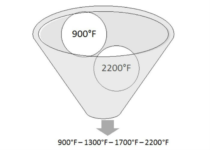
 

Figure 1


We’ve covered the requirements of an initial TUS; we will now address the conditions when an initial TUS is required. Initial TUSs are required when a) the furnace is installed (new or used) and b) when any modifications are made that can alter the temperature uniformity characteristics. You could dispute this by stating if a TUS fails (and the furnace is then repaired to be put back in service), if the qualified work zone is expanded, if a thicker control thermocouple is installed, etc. a new initial TUS is required. I would agree, but these would all fall under “B”.

Periodic Temperature Uniformity Surveys

Periodic TUSs are performed for single operating ranges greater than 600°F. In this case, the temperatures are selected must be 300°F from the minimum- and 300°F from the maximum-qualified operating range. If there is a gap of greater than 600°F, additional temperatures must be selected so there is no gap greater than 600°F. Using the example above, we could select temperatures as stated in Figure 2 below.
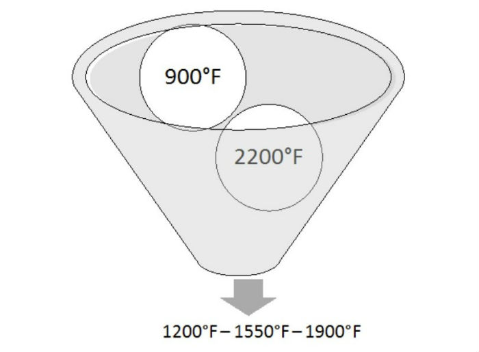
 

Figure 2


It is required that at least once each calendar year the minimum and maximum temperatures of the qualified operating range (in our example, it would be 900°F and 2200°F) are tested. Some suppliers may choose to perform an initial TUS once per year to ensure they capture the minimum and maximum.

Initial and Periodic Test Frequency

Tables 8 and 9 within AMS2750E describe the TUS frequency which is based both on furnace Class and Instrumentation Type. As an example, if our furnace referenced previously was identified as a Class 3 (±15°F), Type A instrumentation, the initial survey frequency would be quarterly. After two successful consecutive surveys, the frequency of testing could then be extended to being done annually.

It is important to recognize the difference between initial and periodic TUS temperatures and initial and periodic TUS frequency. Let’s use our example to expand on this. The supplier would perform a TUS using initial temperatures shown in Figure 1. If the TUS passes, the supplier would then, three months later, perform a TUS using the temperatures shown in Figure 2. This would then count as two successful consecutive TUSs. The next TUS could then be performed annually using the temperatures stated in Figure 2.

Conclusion

Understanding initial and periodic TUS requirements is imperative to ensure conformance to AMS2750E and Nadcap. In the next installment, we will discuss TUS data collection, relocation of hot and cold thermocouples, as well as quality requirements.

Submit Your Questions

Please feel free to submit your questions, and I will answer appropriately in future articles. Send your questions to editor@heattreattoday.com.


Jason Schulze on AMS2750E: Initial and Periodic Temperature Uniformity Surveys Read More »

Jason Schulze on AMS2750E: Examining Requirements That Apply to TUS Thermocouples


This is the sixth in a series of articles by AMS2750 expert, Jason Schulze (Conrad Kacsik).  Click here to see a listing of all of Jason’s articles on Heat Treat Today. In this article, Jason advances the discussion of TUSs with an examination of requirements that apply to TUS thermocouples. Please submit your AMS2750 questions for Jason to editor@heattreattoday.com.


Introduction

Any technician who has performed a temperature uniformity survey understands that the assembly, use, and placement of thermocouples are imperative to the success of the TUS.

As we move through the requirements of Temperature Uniformity Surveys, in this installment we examine the requirements which apply to TUS thermocouples.

TUS Thermocouples Re-Use, Quantity, and Arrangement Requirements

TUS Thermocouple Re-Use Requirements

AMS2750E, paragraph 3.1.3, can be difficult to understand at times. To start, it’s important to understand the difference between expendable and nonexpendable thermocouples.

Expendable Thermocouples:

“Thermocouples made of fabric or plastic covered wire. The wire is provided in coils or on spools. Insulation usually consists of glass braid or ceramic fiber cloth on each conductor plus glass braid overall.”

Nonexpendable Thermocouples:

“Thermocouples that are not covered with fabric or plastic insulations. One type consists of ceramic insulators over bare thermocouple wire, sometimes inserted in a tube for stability and protection. A second type consists of a combination of thermocouple wires, mineral insulation, and a protecting metal sheath compacted into a small diameter. The thermocouple thus constructed is protected, flexible and, within the temperature limits of the sheath material, may be used many times without insulation breakdown. This type of thermocouple, conforming to ASTM E 608, is available under many trade names.”

Once these definitions are understood, we focus on paragraphs 3.1.3.3, 3.1.3.4, and 3.1.3.5 carefully to ensure you apply the correct usage allowance to the correct thermocouples.

Paragraph 3.1.3.3:

“Expendable test sensors may be reused if ‘U’ in the following formula does not exceed 30. A ‘use’ for test thermocouples is defined as one cycle of heating and cooling the thermocouple (2.2.77). U = Number of uses below 1200 °F (650 °C) + 2 times number of uses from 1200 °F (650 °C) to 1800 °F (980 °C). Expendable base metal test thermocouples shall be limited to a single use above 1800 °F (980 °C).”

Notice the paragraph begins with the term “expendable test sensors.” This prohibits the U-formula from governing the replacement frequency of nonexpendable test sensors as well as expendable sensors which are not used as a test sensor.

Paragraph 3.1.3.4:

“Any base metal TUS thermocouple that is (1) used exclusively under 1200 °F (650 °C), (2) identified, and (3) preserved/protected from damage (i.e., crimping, excessive moisture contact, corrosion, etc.) between tests or remains installed on a rack that is protected between tests,) shall be limited to no more than 90 uses or 3 years, whichever comes first and may be reused subject only to the limitations of 3.1.3.1 to 3.1.3.2.”

This paragraph begins with “Any base metal TUS thermocouple.” This would apply to any base metal thermocouple (i.e. Type K, Type N, etc.) used for a TUS, whether expendable or nonexpendable.

Paragraph 3.1.3.5:

“Nonexpendable base metal TUS thermocouples reinstalled for each TUS through ports in the furnace, used in the same location and depth of insertion for each TUS and used exclusively under 1200 °F (650 °C) shall be limited to no more than 90 uses or 3 years, whichever comes first and may be reused subject only to the limitations of 3.1.3.1 to 3.1.3.2.”

This paragraph is very specific regarding its application. For this paragraph to apply, the supplier would need to be using a) nonexpendable thermocouples that are b) base metal, which are c) reinstalled through ports in the furnace and used (non-resident) d) at the same location and e) depth of insertion.

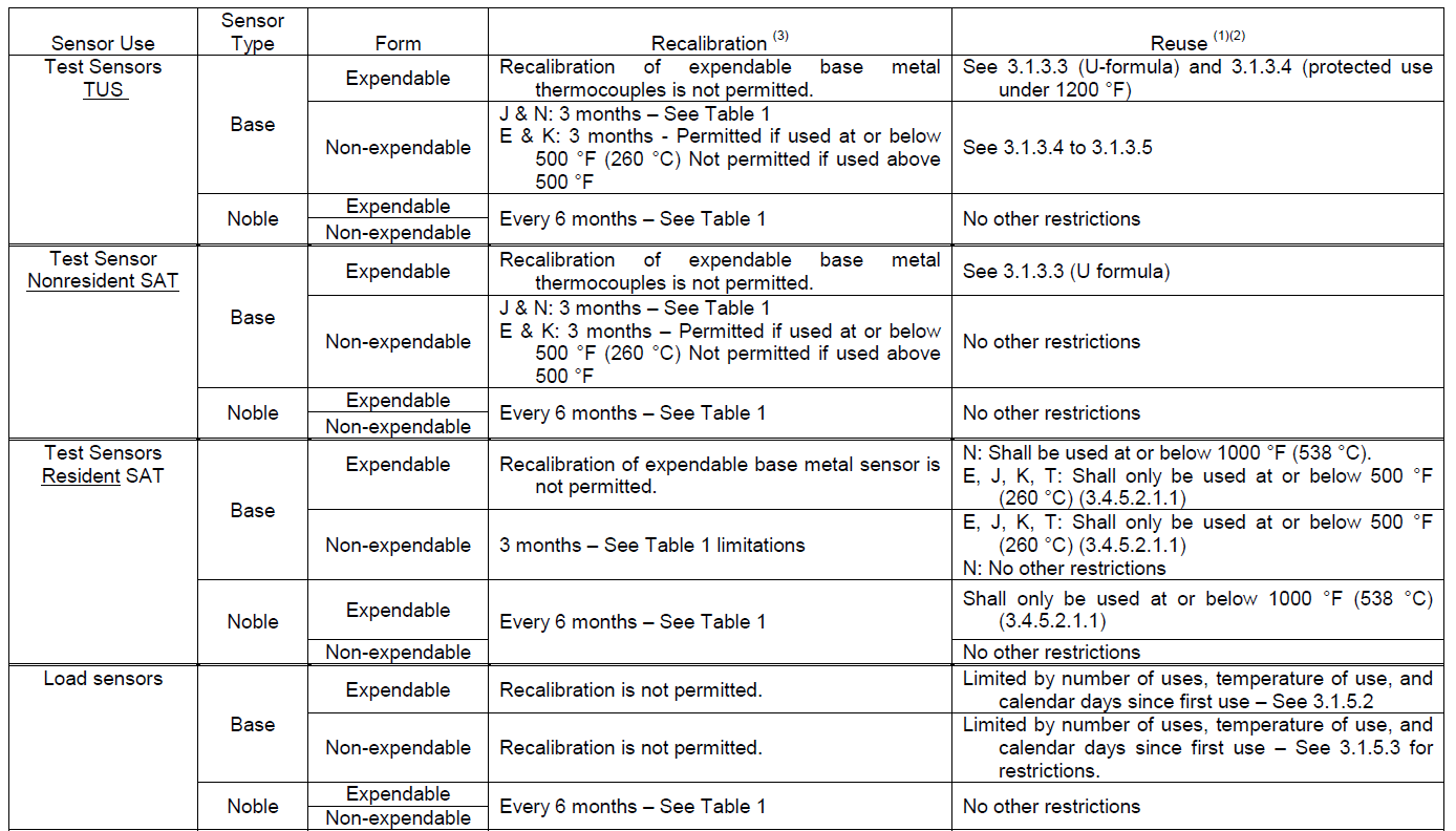
Suppliers interpreting the usage requirements of test thermocouples should pay close attention to Figure #1 in AMS2750E. Figure #1 lays out the usage requirements of AMS2750E in an easy-to-read format that can be used as a quick reference.

Figure 1, AMS2750E


TUS Thermocouple Quantity Requirement

AMS2750E, page 27, paragraph 3.5.13.1, states that the number of TUS thermocouples shall be in accordance with Table 11. The top 2 lines reflect the most widely used. (See Figure 2.)

Figure 2

The amount of test sensors is based on the cubic foot of the qualified work zone. This should not be mistaken for the cubic foot of the heating area in the furnace, or control zone, as the full heating area is not always the size of the qualified work zone.

Table 11 begins by categorizing the options as “Workspace Volume Less Than.” Once your qualified work zone is established, you will need to apply that to the table to determine how many TUS thermocouples will be needed. As an example, if your qualified work zone is 562 cubic feet, you would need a minimum of 19 test thermocouples distributed throughout the qualified work zone during the TUS.

TUS Thermocouple Placement Requirement

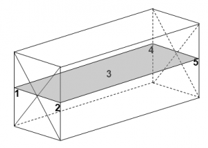
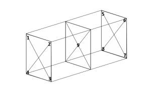
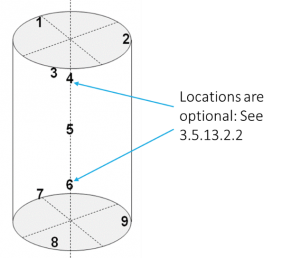
Thermocouple placement is described in AMS2750E paragraphs 3.5.13.2.1 and 3.5.13.2.2. Paragraph 3.5.13.2.1 relates to the thermocouple placement for qualified work zone volumes that are less than 3 cubic feet. Typically, this would apply to small air furnaces or laboratory furnaces used for testing, although could very well apply to smaller atmosphere or vacuum furnaces. Each paragraph describes the requirements for a rectangular qualified work zone and cylindrical qualified work zones.

Paragraph 3.5.13.2.1

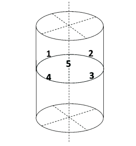
“For furnace work zone volumes less than 3 cubic feet (0.085 m3), four TUS sensors shall be located at the four corners and one at the center. If the furnace work zone volume is cylindrically shaped, four TUS sensors shall be located 90 degrees apart at the periphery and one shall be located at the center. In both cases, all TUS sensors shall be located to best represent the qualified work zone.”

To better describe the requirement within this section, I’ve included a diagram of the requirement for both rectangular and cylindrical qualified work zones.


The location is a requirement, although the numbering sequence identified in these diagrams is optional and the supplier has the freedom to number the locations as they see fit.

Paragraph 3.5.13.2.2

“For furnace work zone volumes greater than 3 cubic feet (0.085 m3), eight TUS sensors shall be located at the corners and one shall be located in the center. If the work zone volume is cylindrically shaped, three TUS sensors shall be located on the periphery of each end, 120 degrees apart. One of the remaining TUS sensors shall be located at the center; the other two shall be located to best represent the qualified work zone. For furnace work zone volumes greater than 225 cubic feet (6.4 m3), the additional TUS sensors required by Table 11 shall be uniformly distributed to best represent the qualified work zone. When radiant heat from the periphery of the work zone is used to heat the product, the additional sensors shall be uniformly distributed at the periphery of the work zone.”

Again, the diagrams to the right better describe the requirements within paragraph 3.5.13.2.2.

Conclusion

Now that the TUS thermocouple requirements have been established, we will move on to the requirements of initial and periodic TUS requirements in the next article.

Submit Your Questions

Please feel free to submit your questions, and I will answer appropriately in future articles. Send your questions to editor@heattreattoday.com.

Jason Schulze on AMS2750E: Examining Requirements That Apply to TUS Thermocouples Read More »
Jason Schulze on AMS2750E: Understanding Key AMS2750E Definitions

This is the fifth in a series of articles by AMS2750 expert, Jason Schulze (Conrad Kacsik).  Click here to see a listing of all of Jason’s articles on Heat Treat TodayIn this article, Jason advances the discussion of TUSs with a lesson on the definitions of key AMS2750E terms. Please submit your AMS2750 questions for Jason to editor@heattreattoday.com.

Introduction

When executing a technical process, understanding the meaning and intent of certain definitions can clarify the interpretation of certain requirements, thereby, altering a specific course based on that interpretation.

In this article, we will focus on the primary definitions associated with temperature uniformity surveys as they apply to AMS2750E.

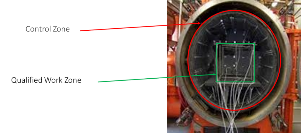
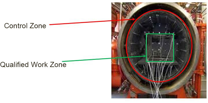
Control Zone vs Qualified Work Zone

Control Zone

AMS2750E, page 44, para 2.2.9: “A portion of the work zone in thermal processing equipment having a separate sensor/instrument/heat input or output mechanism to control its temperature. This portion of a furnace is independently controlled.”

Qualified Work Zone

AMS2750E, page 6, para 2.2.42: “The defined portion of a furnace volume where temperature variation conforms to the required uniformity tolerance.”

It’s important to understand the difference between the two definitions. Below is a figure which outlines the most basic idea behind each.

Figure 1

Failure of a Survey Thermocouple

AMS2750E, page 4, para 2.2.19: “Obviously incorrect or erratic activity of a survey thermocouple indicated by extreme high readings, extreme low readings, and/or erratic changes in readings not reflected by other sensors.”

This situation can be observed by pyrometry technicians in real time as the survey is running. Possible reasons for this may be:

  • a loss in chrome due to vapor pressure (vacuum furnaces only),
  • movement of the thermocouple during the test from the documented position,
  • Polarity reversal during test thermocouple assembly.

Note that AMS2750E allows only a specific number of thermocouples to fail during a TUS (see AMS2750E, page 30, para 3.5.16).

Heat Sink

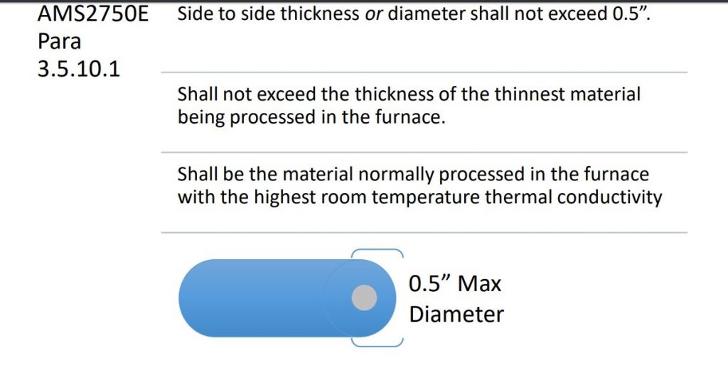
AMS2750E, page 5, para 2.2.24: “A mass of material equivalent to the heat transfer characteristics of the thinnest section of the part being heat-treated. Heat sinks may be used during TUS (3.5.10.1) and during production (3.3.5).”

The use of heat sinks during a TUS is optional. Operators are permitted to utilize heat sinks on both TUS test thermocouples and the load thermocouple being used. The key is to document the initial TUS load condition, including the use of heat sinks, and utilize this configuration on subsequent tests.

If heat sinks are utilized on either the TUS test thermocouples, or the load thermocouples, the heat sink must comply with AMS2750E, page 26, para 3.5.10. Additional requirements and clarification regarding heat sink requirements can be found in the Nadcap Pyrometry Guide on page 47, question #43 and Heat Treat Auditor Advisory 17-007.

Figure 2

Qualified Operating Temperature Range

AMS2750E, page 6, para 2.2.41: “The temperature range of thermal processing equipment where temperature uniformity has been tested and found to be within required tolerances as specified in 3.3”

This temperature range affects multiple aspects of pyrometry, including the instrument calibration setpoints of both furnace instruments (AMS2750E page 14, para 3.2.5.5.1) as well as field test instruments (AMS2750E, page 14, para 3.2.5.4) used on that particular equipment. It also affects what product can be heat treated in the particular furnace.

Field Test Instrument

AMS2750E, page 4, para 2.2.20: “An instrument that is portable, that meets the requirements of Table 3, has calibration traceable to secondary equipment or better and is used to conduct on-site tests of thermal processing equipment.”

One of the key points in this definition is the term “portable”. This implies that furnace instruments cannot be used as field test instruments. For those new to pyrometry, this may cause confusion as a single instrument make and model could be designated as a field test instrument or a furnace instrument. As an example, consider a Yokogawa DX model electronic recorder. A supplier could buy two of the same model and use one as a furnace recorder and the other as a TUS recorder (making it a field test instrument). The only differences are its designated use, calibration points, and the fact that is independent from the furnace (portable).

Field test instruments must be calibrated using a standard instrument or better at 6 points per AMS2750E, page 14, para 3.2.5 and have an accuracy of ±1°F or 0.1%, whichever is greater.

Temperature Uniformity

AMS2750E, page 7, para 2.2.66: “The temperature variation (usually expressed as ± degrees) within the qualified furnace work zone with respect to set point temperature. For retort furnaces where a sensor in the retort is used to control temperature, the temperature variation is with respect to the sensor in the retort and not to the furnace set temperature.”

This relates directly to the furnace class designation per Figure 2 of AMS2750E. It’s important to keep in mind question #21 of the Hwhen designating furnace class.

Temperature Uniformity Survey

AMS2750E, page 7, para 2.2.68: “A test or series of tests where calibrated field test instrumentation and sensors are used to measure temperature variation within the qualified furnace work zone prior to and after thermal stabilization.”

As any pyrometry technician knows, one of the main issues to watch for is thermal inertia, or overshoot. Any overshoot will be cause for immediate failure and initiation of an internal RCCA per AMS2750E, page 34, para 4.2.

Conclusion

Understanding AMS2750E definitions will be advantageous to readers of the remaining articles in this TUS series.

We will next discuss the differences between periodic surveys, initials surveys and more.

Submit Your Questions

Please feel free to submit your questions and I will answer appropriately in future articles. Send your questions to editor@heattreattoday.com.

Jason Schulze on AMS2750E: Understanding Key AMS2750E Definitions Read More »

Jason Schulze on AMS2750E: The Importance of Temperature Uniformity

This is the fourth in a series of articles by AMS 2750 expert, Jason Schulze (Conrad Kacsik).  The first three dealt with SATs — System Accuracy Tests — both the Standard SAT and the Alternate SAT. Click here to see a listing of all of Jason’s articles on Heat Treat TodayIn this article, Jason sets some of the groundwork for a discussion of TUSs — Temperature Uniformity Surveys — by addressing the importance of a uniform furnace. Please submit your AMS 2750 questions for Jason to editor@heattreattoday.com.


Introduction

Temperature Uniformity Surveys (TUS) are an important part of testing any furnace to ensure consistent and uniform product results. In the next few posts, we’ll discuss not just the importance of temperature uniformity surveys, but also the requirements set forth by AMS2750E as well.

The Importance of a Uniform Furnace

Although a uniform furnace is important for all heat treating processes, I will utilize my experience in brazing to explain the importance of temperature uniformity within a furnace. Even if you may be unfamiliar with brazing, the logic should be straightforward.

Brazing depends on the eutectic reaction in a braze filler metal to bond two materials together. Temperature, atmosphere, and (when applied) vacuum greatly influence the reaction; with respect to this article, we will only deal with temperature uniformity as it applies to AMS2750E and Nadcap.

Brazing is inherently sensitive in the majority of aerospace applications. As a consequence, tight temperature tolerances are typically applied to brazing processes: anywhere from ±15°F to a super-tight ±5°F.

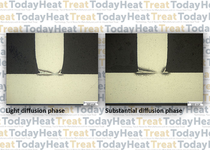
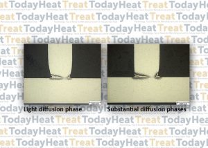
Here’s a practical example. We are developing a diffusion braze process in which two widgets are brazed together using Ni braze filler material. We load a single layer of widgets on a flat ceramic plate: one in each corner and one in the middle. This gives us five samples in total.  Once our development cycle is complete, we take the samples to the laboratory for examination of the required diffusion depth. In the lab, we notice that the samples located in the rear of the furnace (farthest from the door) have considerably less diffusion than the samples in the front (nearest the door) and the middle.


In a case like this, we would immediately look at the most recent TUS. If we notice that the uniformity requirement is ±25°F with actual TUS results being +20°F/-18°F (which does conform to a ±25°F), Temperature Uniformity Surveys should not be considered arbitrary. If tight temperature tolerances are required by your customer, it is safe to assume there is a good reason for it, and we should take seriously the need to keep our furnaces in top shape and capable of passing customer and/or AMS2750-required temperature uniformity surveys.

This first TUS article discussed the importance of temperature uniformity requirements as they are passed down to us from a purchase order (PO) holder to a supplier. In following articles, we will begin discussing definitions from AMS2750E and Nadcap to ensure we have a proper understanding of the terms as we implement requirements.

Submit Your Questions

Please feel free to submit your questions and I will answer appropriately in future articles. Send your questions to editor@heattreattoday.com.


Jason Schulze on AMS2750E: The Importance of Temperature Uniformity Read More »

Jason Schulze on AMS2750E: “Flow Down”

______________________________________________________

A reader whose company offers sintering and heat treating of medical devices recently submitted an inquiry regarding AMS2750 specifications and sintering.

READER QUESTION: “Does insipient melting of metal particles fall under these guidelines?  Our temperatures go as high as 2650°F and finding cost-effective ways to utilize thermalcouples to verify TUS temperatures seems a difficult task in itself.” Heat Treat Today‘s resident AMS2750 expert Jason Schulze (Conrad Kacsik) provided the following response.  Submit your AMS2750 questions to Jason at editor@heattreattoday.com.

______________________________________________________

Introduction

Understanding whether AMS2750E should be implemented within your process can be confusing. In this post, we will focus on understanding when AMS2750E is applicable to a supplier and when this should be verified.

What is “Flow-Down”?

Within most industries, there exists some type of flow down with regards to specific requirements. When we purchase a car, there are loan terms which flow down to a purchaser via a loan contract, such as interest rates, the number of months included in the loan, the ratio at which payments are distributed to interest and principal, as well as the requirement to carry full coverage car insurance for the life of a vehicle loan. These details are requirements which flow down to the purchaser via a contract.

The same can be said of a manufacturer or processor in the aerospace, commercial, or automotive industry. Certain requirements flow down from a purchaser (PO holder) to the supplier (entity receiving the purchase order).

Order of Precedence

In the aerospace and automotive industry, the flow down of requirements typically will encompass three documents in a specific order of precedence: 1) purchase order, 2) part print, and 3) process specifications. This is considered the order of precedence with regards to specific requirements.

Let’s look at an example:

ABC Aerospace issues a purchase order for turbine blades to be manufactured at Ajax Machine. Ajax Machine has several multi-axis grinding machines as well as captive heat treating. ABC Aerospace issues a purchase order to Ajax Machine that states the following:

“Part Number 30925-96 – 1,050 pc. Due January 1st, 2050 per Rev B 30925-96 Print”

Ajax Machine obtains the PO as stated above, along with the part print stated on the purchase order. The part print states multiple dimensional requirements for the turbine blades, but it also states a heat treat requirement to an industry heat treat specification. This heat treat specification would identify multiple variables such as time, temperature, and atmosphere for heat treatment; it may also specify that all furnaces used for heat treatment shall conform to AMS2750E, if the PO holder (customer) does, in fact, require this.

For a supplier attempting to understand if AMS2750E applies to their specific process, flow down from the PO holder is where this requirement is established.

Establishing Flow Down via Contract Review

To become ISO certified, a company must have a contract review procedure. Contract review is typically used to establish flow down requirements to ensure that a supplier is able to meet the requirements a purchaser has requested. Utilizing the contract review process to establish flow down requirements ensures that the supplier will document, establish, and verify all flow down requirements stated on the PO, part print, and process specification prior to manufacturing.

Conclusion

Flow down, as it relates to AMS2750 as well as other variables, is an important step in successful manufacture and processing of aerospace, commercial, and automotive hardware.

Submit Your Questions

Please feel free to submit your questions and I will answer appropriately in future articles. Send your questions to editor@heattreattoday.com.

Jason Schulze on AMS2750E: “Flow Down” Read More »

Jason Schulze on Understanding AMS 2750E — Alternate SAT

Heat Treat Today Original ContentJason Schulze, Conrad Kacsik Instruments, Inc.


This is the third in a series of articles by AMS 2750 expert, Jason Schulze. Please submit your AMS 2750 questions for Jason to Doug@HeatTreatToday.com.


Introduction

Of all the changes made to AMS2750 through the years, the Alternate Systems Accuracy Test (ALT SAT) is arguably the one that has had the largest impact within the heat treat industry. The requirements for the ALT SAT, as presented in AMS2750E, make up just 0.008% of the specification as a whole; yet these requirements account for an inordinate amount of time spent on discussion and debate.

Below, we’ll discuss the requirements of the ALT SAT as they are presented in both AMS2750E, and in the Nadcap Pyrometry Guide.

ALT SAT Applicability

Prior to revision E of AMS2750, a load thermocouple that was single-use, or which was replaced more often than the applicable SAT frequency, did not require an SAT of any kind. During the time period when Revision D was in effect, the Alternate SAT did not exist. This meant that if you used a load thermocouple and had a documented single-use statement or replacement schedule, which ensured the usage did not exceed the applicable SAT frequency within your internal procedures, that particular load sensor was not subject to the SAT requirements of AMS2750D.

AMS2750D page 14, paragraph 3.4.1.2

3.4.1.2 An SAT is not required for sensors whose only function is over-temperature control, load sensors that are limited to a single use (one furnace load/cycle), sensors not used for acceptance as part of production heat treatment, or load sensors whose replacement frequency is shorter than the SAT frequency. See 3.1.8.4 and 3.1.8.5.

When AMS2750E replaced AMS2750D, the ALT SAT was introduced. In addition to the ALT SAT, paragraphs 3.4.4 through 3.4.4.3 were also inserted:

AMS2750E pg 19, para 3.4.4

3.4.4 The SAT can be accomplished using any one of 3 methods:

3.4.4.1 Perform an SAT following the requirments in 3.4.5

3.4.4.2 Alternate SAT process defined in 3.4.6

3.4.4.3 SAT Waiver process, as described in 3.4.7

By stating that the SAT “…can be accomplished using any one of 3 methods”, this section has often been misinterpreted to mean that a supplier may simply choose which type of SAT they wish to implement. This is not the case.

An ALT SAT must be performed on any thermocouple that is either

  1. single use, or
  2. replaced more often that the applicable SAT frequency.

Throughout the industry, these two items typically apply to load thermocouples. As an example, let’s assume that a non-expendable load thermocouple is used in a furnace that is designated as a Type A, Class 5 furnace. This would put the standard SAT frequency at quarterly (no SAT extension & parts-furnace). If the non-expendable load thermocouple that was used had a documented replacement frequency of monthly, the ALT SAT requirements would apply to this particular load thermocouple.

In the example above, a supplier could not accomplish the SAT “…using any one of the 3 methods” – the ALT SAT requirements would be required for that particular load thermocouple system and would need to be accounted for in the supplier’s internal pyrometry procedure.

ALT SAT Requirements

The ALT SAT requirements can be split up into a single main requirement and two sub-requirements which suppliers may choose to implement.  The main requirement is:

  • Calibration of instruments at the point at which the sensor is connected.

This means that, wherever the thermocouple is connected directly, instrument calibration must take place at this point. Let’s look at a vacuum furnace as an example.

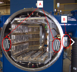
Vacuum Furnace showing Location A and Location B for an Alternate SAT
Vacuum Furnace showing Location A and Location B for an Alternate SAT (photo courtesy: PVT Inc.)

Location A indicates where load thermocouples will be plugged in directly. Location B is where the extension wire from inside the furnace travels to the outside of the furnace and then on to the recording instruments. Location A is where the calibration of the recording instrument must take place per the ALT SAT requirements. This requirement in no way changes the standard requirements for instrument calibrations as they are presented in AMS2750E; it only specifies exactly where the instrument calibration must take place within the furnace sensor system. Your internal pyrometry procedure must state that this is a requirement.

The next paragraphs, 3.4.6.1.1 & 3.4.6.1.2, are where the supplier must read and understand both paragraphs in order to make a choice regarding which option best suits their furnace set-up and production. Let’s break both paragraphs down.

Option Number 1

3.4.6.1.1 - Establish appropriate calibration limits for sensors which when combined with the calibration of the instrument/lead wire and connector, will meet the SAT requirements of Table 6 or 7, as appropriate.

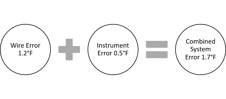
There are several ways to go about conforming to this paragraph. Keep in mind, that when choosing an option you are dealing with 2 variables; the error of the instrument which records the thermocouples in question and the error of the thermocouples themselves.

a) This option relieves you of one of the variables stated above. When calibrating your instruments which the thermocouples are plugged in to, ensure there is absolutely no error at all. Adjustments (offsets) may need to be made to accomplish this. This means that, if you do not permit offsets currently, you will either need to account for them in your procedures or choose option “b” below. Once you’ve established that your instrument has no error, you restrict the error of the thermocouples you purchase not to exceed the appropriate SAT difference stated in Table 6 or 7.

As an example, let’s assume you have a vacuum furnace that uses 2 load thermocouples which are single use only. The furnace is classified as a Type A, Class 2 furnace – this means the Maximum SAT difference is ±3°F or 0.3% of the reading.  You would ensure that the recording instrument for those 2 channels recording the load temperature have no error. Then, order load thermocouples which have an error of ±3°F or 0.3% of the reading, or less.

b) This option is most attractive to those who do not wish to allow offsets within their heat treat operation. To accomplish this, you compare the error of the specific channels of the instrument the thermocouples in question plug into, to the error of the thermocouples themselves. The resulting value cannot exceed the maximum error permitted for the appropriate furnace class. Internal pyrometry procedures specifically state how thermocouple wire will be received and the ALT SAT calculation accomplished prior to releasing the thermocouple wire to production. There are two variables that must be verified in this option. Anytime one of these two variables change, the calculation must be obtained. The Nadcap Pyrometry Reference Guide requires that this calculation be evaluated at the instrument (chart recorder) calibration points (min, max & middle 1/3rd.)

Overview of a Calculation – Single Temperature

For Your Consideration

There has been some confusion in the industry that the ALT SAT process, specifically Option B above, must be accomplished at the furnace. This misunderstanding includes suppliers using a Field Test Instrument to simulate the min, max and middle 1/3rd of the instrument calibration temperatures in an effort to obtain the error of the instrument channels in question. This amounts to nothing more than an additional instrument calibration; one could simply obtain the error from the current instrument calibration instead of performing extra work at the furnace.

Option A and B above would be performed as a desk operation; none of the tasks would be performed at the actual furnace.

Conclusion

The ALT SAT process has been successfully implemented by many suppliers in the Aerospace Industry; both Nadcap approved and non-Nadcap. As with any AMS2750E process, detailed procedures and training are key to executing the ALT SAT process.

Submit Your Questions

Please feel free to submit your questions and I will answer appropriately in future articles. Submit your questions by sending an email to doug@heattreattoday.com.

Jason Schulze on Understanding AMS 2750E — Alternate SAT Read More »

Jason Schulze on Understanding AMS 2750E — Standard SAT Description

Dan Bender, Understanding the Short Circuit Current RatingJason Schulze, Conrad Kacsik Instruments, Inc.


This is the second in a series of articles by AMS 2750 expert, Jason Schulze. Don't miss the Q&A section at the bottom of this article and please submit your AMS 2750 questions for Jason to Doug@HeatTreatToday.com.


Introduction

Considering the abundant number of Nadcap heat treat audits performed in a single year, the area receiving the most findings is pyrometry, and within this group, system accuracy testing (SAT) is the third most common finding.

The SAT process has been refined through each revision of AMS2750 (C through E). We’ve seen SAT thermocouple requirements, for example, gradually incorporated into the tables but not within the body of the specification. Also, we’ve seen the definition of a SAT incorporated into revision D within the definitions section; however, with revision E it was added to the body of the specification.

AMS2750E presents three optional methods for performance of SATs that must be implemented; the Standard (or Regular) SAT, the Alternate SAT, and the SAT Waiver. Within this article, we will focus on the Standard SAT process.

Standard SAT Description – AMS 2750E

AMS2750E has defined the Standard SAT as:

An on-site comparison of the instrument/leadwire/sensor readings or values, with the readings or values of a calibrated test instrument/leadwire/sensor to determine if the measured temperature deviations are within applicable requirements. Performed to assure the accuracy of the furnace control and recorder system in each control zone.

Put simply, an SAT is a comparison of two systems: the furnace system (whether control, monitoring, or load) against a test system. It’s important to recognize that the comparison is being made against two systems and not against an instrument or thermocouple alone. Each system is made up of three variables:

  1. the instrument
  2. the lead wire
  3. the sensor


image-1

SAT Procedure

There is no general SAT procedure that can be applied for every supplier. Each supplier has their own needs as well as their own mechanical arrangement of thermocouples within their furnace system. The key to conformity is to ensure that, once a method for performing an SAT on a furnace is established, it is documented (i.e., in detail, including photos, if necessary) and repeated each time an SAT is performed. Some requirements to incorporate into your system are:

1) The tip-to-tip distance between the furnace system thermocouple and the test system thermocouple cannot exceed 3 inches.

2) The test thermocouple shall be in the same position/depth as the initial test.

3) The furnace is cycled and maintained at a temperature normally used during production.

4) Each system that makes up the applicable instrumentation type must be tested.

SAT Difference

Many findings arise from suppliers calculating the SAT Difference incorrectly. AMS 2750E states the following as a way to calculate the SAT Difference.

The difference calculated between the reading of the furnace sensor system being tested (sensor, lead wire, and instrument) and the corrected reading of the test sensor system (after test sensor and test instrument correction factors are applied) shall be recorded as the system accuracy test difference. Applicable correction factors shall be applied algebraically.

I’ve highlighted the word “corrected” as it applies to the test instrument systems because this seems to be a source of frequent findings. The furnace system does not get corrected, the test system does get corrected.


image-2

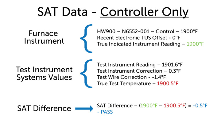
As an example, let’s consider a vacuum furnace which has had an SAT performed. The vacuum furnace is designated a Class 3 (±15°F) Type D furnace. Let’s assume no additional furnace thermocouples are employed and we are performing an SAT on the control and recording systems. The readings obtained are below in the picture.

image-3


*The example above is not an SAT Certification. It’s an example of how to calculate the SAT Difference in a given situation.

Conclusion

SATs can be difficult depending on the equipment and processes suppliers have. As always, it’s important to receive comprehensive training regarding the specific requirements of System Accuracy Testing as they apply to your facility. There are many particular aspects of SATs that may not have been accounted for in this article. If you have specific questions, please email them to doug@heattreattoday.com, and I will answer them in an upcoming article.

Submit Your Questions

Please feel free to submit your questions, and I will answer appropriately in future articles.

Out next topic will focus on the requirements and execution of an Alternate SAT per AMS2750E, the requirements of AC7102/8 and the Pyrometry Guide.   


Q/A with Jason Schulz

Q: When calculating the SAT Difference, should I include the correction factors of the furnace sensor?

A: No, the correction factor from the furnace sensor is not to be included in the SAT Difference calculation.

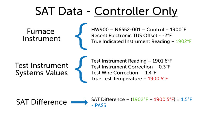
Q: How do I account for an internal (pre-programmed) TUS offset within the controller when calculating the SAT Difference?

A: Internal or electronic TUS offset must be algebraically removed when calculating the SAT Difference.  Below is an example that includes an electronic TUS offset of -2°F.


sat-qa

Q: I operate a furnace with 2 load sensors. One of them is used to signal the start and end of each soak cycle, the other is reference only. Do I have to perform an SAT on the load thermocouple I use as a reference only thermocouple?

A: Any thermocouple that is not used as product acceptance may be deemed reference only and is not subject to the SAT requirements of AMS2750E. Nadcap requires that the reference only thermocouples be accounted for in internal procedures.

Q: When performing my bi-weekly SAT, I get a difference of +2.6°F on one test and two weeks later I get a difference of -3°F; this constitutes a spread (within two weeks) of 5.6°F. Would this be cause for SAT failure?

A: According to AMS2750E and Nadcap, no, this would not constitute a failed SAT, though is something to be cautious of. This type of shift in SAT results does reflect some sort of change or degradation of the system being tested. A well-established tack, in this case, is to plot SAT results as part of an SPC (statistical process control) program which will govern future replacement of system thermocouples and/or leadwire (in the case when large difference is SAT results over a pre-determined amount). A documented SPC system for SAT results would also satisfy the requirements of AC7102/8(NA) page 2, paragraph 3.12.

Jason Schulze on Understanding AMS 2750E — Standard SAT Description Read More »

Jason Schulze on Understanding AMS 2750E — The 1st of Many…

Dan Bender, Understanding the Short Circuit Current Rating Jason Schulze, Conrad Kacsik Instruments, Inc.

Introduction

Within the aerospace heat treating field, Nadcap heat treat audits are a necessary part of doing business.  The requirement to obtain Nadcap approval is “flowed down” from primes like Boeing and Airbus to sub-tier suppliers and these approvals must be maintained. Nadcap heat treat audits are typically more difficult than other audits and this is due primarily to the inclusion of pyrometry.

My name is Jason Schulze. I’m a metallurgical engineer with over 20 years in the aerospace industry. I’ve been exposed to Nadcap in multiple commodities, although often focused in heat treat. I work with companies to insource and improve special processes, perform gap-analysis and internal audits as well as gain Nadcap approval. I am also contracted by PRI as an eQualern Instructor and teach multiple courses including pyrometry.

In the upcoming series of Heat Treat Today articles, I’ll present specific subjects related to Nadcap heat treat audits and pyrometry. In subsequent articles, I hope to be answering your questions – questions submitted by our readers.

In this initial article, I’ll focus on AMS2750E comprehension as well as offering a Quality based perspective with regards to accounting for each requirement within the specification.

Understanding AMS2750E

As with any specification, it must be read carefully. It would do no good to read the specification and attempt to implement it if you do not understand the material. On a scale of 1-10, with 1being zero knowledge of pyrometry, someone reading AMS2750E for the first time would need to be at least a 5 in order to properly comprehend and implement the AMS2750E Specification.

Most quality engineers are familiar with the term “bubbling” as it relates to blue prints. Bubbling a print is a practice in which each requirement is assigned a sequential number. Once this is done on the print, it is then logged onto a form which contains the designated number, its associated requirements, the subsequent result, and an accept/reject notice. Typically, this is done on machined parts that may have an intermediate process (such as heat treat) involved in their manufacture. When an intermediate process is performed, the specification is simply listed as the requirement and an accept designation is applied. The specification itself is not bubbled, but read by an engineer, and the applicable requirements flowed down.

My method is to bubble the specification itself. Take each requirement out of the specification and assign it a sequential number. Let’s call them “Characteristic Requirements”. Some paragraphs may have several requirements within a single paragraph; each would be separated and assigned its own sequential number. Let’s look at an example of this:

AMS2750E PG 19, PARA 3.4.5.1:

“The displayed temperature indication and/or recording of the sensor being tested as used in production, with appropriate offsets or correction factors, at any operating temperature, shall be compared with the corrected temperature indication of the test sensor on a test instrument”

It may seem that a single requirement is being put forward; but there are actually 7 contained within this one paragraph.

  1. The displayed temperature indication…
  2. and/or recording of the sensor being tested…
  3. as used in production…
  4. with appropriate offsets or correction factors [option for either]
  5. at any operating temperature…
  6. shall be compared with the corrected temperature indication of the test sensor…
  7. on a test instrument.

I have performed this task on both AMS2750D and AMS2750E. Revision E ended with 513 characteristic requirements, including tables and figures. Once bubbled, each requirement must be accounted for as they apply to your operations. For example, any requirement regarding a retort furnace would be designated “N/A” if your operation employed only vacuum furnaces. Of course, the continuing issue of comprehension arises at each step of this process. If you have a poor understanding of pyrometry it will be difficult to bubble AMS2750E, and nearly impossible to successfully complete the process of showing conformance.

AMS2750E Training

By training, I’m referring to comprehension of AMS2750E itself. Instruction on how to properly calibrate an instrument, perform an SAT or wire up a rack to perform a TUS will be much easier once AMS2750E is understood.

Several courses are offered through multiple companies.  Choosing one where you will obtain practical and sound advice concerning your specific operation as it relates to AMS2750E is the key. Get pyrometry training from an engineer who not only has performed the work in accordance with AMS2750E, but more importantly, has been involved in the actual manufacturing of heat treated hardware and has been through a live Nadcap audit. Knowledge in pyrometry may be one thing; its real-time application within an actual production environment is entirely different – and invaluable.

Conclusion

Ensure your comprehension of AMS2750E is in line with Nadcap’s expectations; training will be the key. This will expedite your success in implementing AMS2750E as it applies to Nadcap.

Submit Your Questions

Please feel free to submit your questions and I will answer appropriately in future articles. Email your questions to Doug@HeatTreatToday.com.

Jason Schulze on Understanding AMS 2750E — The 1st of Many… Read More »

Reader Feedback: On TUSs and SATs

Here is what readers are saying about recent posts on Heat Treat Today. Submit your comments to editor@heattreattoday.com.


On Jason Schulze’s article, “AMS2750E: The Importance of Temperature Uniformity” (click here to see original article):

READER QUESTION (from a heat treat supplier across multiple industries):  My vacuum furnace uses a type S thermocouple, and there is no access to perform the SAT. Is there an alternative? (We supply to aerospace and must be in accordance with 2750E.)

Jason Schulze (Conrad Kacsik) for HTT:Jason Schulze, Aerospace Heat Treating
If you do not have access to the hot-junction (measuring tip) of the control thermocouple, an option would be to purchase a dual-element thermocouple.
If you are not familiar with dual-element thermocouples, they have two thermocouples in one small Inconel sheath. You can purchase a Type N and a Type S in a single sheath. The type N can be used as a resident SAT thermocouple. This will give you access to the connection-end of both the control thermocouple and a resident SAT sensor that is in the same sheath.
The only set-back in this situation would be the re-calibration or replacement of the dual element thermocouple every 3 months (per AMS2750E – Resident SAT sensors).

READER QUESTION: [I] just have two questions, one in regards to SAT and one in regards to TUS.

[Question 1] When SAT testing a lead sensor, let’s just say for the purpose of this example this lead sensor is a type “k” base metal thermocouple, is it acceptable to test this sensor against an SAT sensor which is also type “k”? I see that for resident SAT, the sensor should be of a different type, but for non-resident SAT, is this acceptable?

[Question 2] My other question is in regards to TUS, specifically para 3.5.18 of AMS2750E. I see that in this paragraph two options are addressed. I have a decent understanding of the first requirement, the second option is where I’m getting a bit confused which states ” . . . or if the difference between the measured temperature at the current recording locations and the actual respective hottest and coldest measured areas is less than the SAT tolerance for the applicable furnace class.” How does one calculate this difference?

Jason Schulze for HTT:

[To question 1] As long as the SAT thermocouple is not a resident SAT thermocouple, you are permitted to use the same type (i.e., K, J, T, etc.) as the thermocouple being tested.

[To question 2] I’ll use an example to work the next question. We will assume the furnace is a Class 2 (±3°F SAT difference). Let’s say a previous TUS had a hot location at #5 and it was +6°F. On a new TUS,  the location changed to #9 and is now +2°F. The difference between the previous location and the current one is 4°F. This 4°F difference is more than the applicable SAT tolerance of ±3°F, therefore, the location would need to be moved from #5 to #6.

READER REPLY:  In regards to the TUS requirement, I’m assuming the actual M.P. Reading(s) from the current hottest and coldest locations don’t get compared to the respective hottest and coldest locations on the TUS report? For example, I have a furnace that’s classified as class 1 (±5) surveyed at 385°F. The TUS report is stating that the lowest T/C location was 382°F T/C 8. I have now exceeded half the maximum temperature uniformity tolerance (2.5°F), therefore I must relocate unless the difference between the “current recording location” and the actual respective coldest location per the TUS is less the SAT tolerance. I was under the impression that as long as the cold location per the report T/C 8 382°F, when compared to the furnace low multipoint reading during the survey – being less than 2°F, it would not require relocation as my “current recording location” when compared to the actual respective cold location is less than the SAT tolerance. My understanding now is that the process control sensors are not used for this difference calculation but rather the TUS sensor representing the low location? I believe that the “current recording location” statement is where I’m getting thrown off a bit.

Jason Schulze:

You are correct in stating that the comparison is made between the previous and current hot or cold (respectively) locations and not the control thermocouple. AMS2750E is not that easy to follow in some instances so any confusion is understandable.


READER QUESTION (from a metals castings provider for aerospace and defense):  For 1020°F SAT, if test instrument/thermocouple reads 1015°F and temperature controller reads 1020°F, it is acceptable to program -5°F bias/offset in controller so temp controller reads 1015°F, matching test instrument/thermocouple, correct?

Jason Schulze for HTT:

You are able to utilize offsets to the limits of AMS2750E table 6 or 7 to correct both TUSs and SATs. Instrument calibration is a bit different. AMS2750E does not invoke limitations regarding an offset due to instrument calibration.

Your comment regarding the application of a -5°F offset to correct the SAT would, in fact, be permitted according to AMS2750E. One thing that would be required is, if the SAT failed and that is why the offset is needed, there would need to be an internal corrective action and product impact investigation.


We welcome your inquiries to and feedback on Heat Treat Today articles. Submit your questions/comments to editor@heattreattoday.com.

Reader Feedback: On TUSs and SATs Read More »

Reader Feedback: On TUS

Here is what readers are saying about recent posts on Heat Treat Today. Submit your comments to editor@heattreattoday.com.


Jason Schulze, Aerospace Heat Treating
Jason Schulze, contributing editor to Heat Treat Today, author of "AMS2750E: The Importance of Temperature Uniformity"

Joe Powell, President, Intensive Quench Technologies, on Jason Schulze's article, "AMS2750E: The Importance of Temperature Uniformity" (click here to see original article):

Interesting to me how big a deal specs make on temperature uniformity in the hot zones, and how little attention is paid to quantifying the uniformity of the quench cooling process!  But we all know predictable distortion and uniformity of mechanical properties can only happen when the quench cooling is uniform!


Bill Jones, CEO Solar Atmosphere, on Jason Schulze's article, "AMS2750E: The Importance of Temperature Uniformity" (click here to see original article):

Let us assume a standard box furnace air atmosphere operating at 1650f with a plus-minus 25f delta T. What first areas would you recommend to look for improvement.

Jason Schulze (Conrad Kacsik) for HTT:

When I had issues achieving uniformity, I typically focus on the position of the control thermocouple 1st, then work my way to other items.

From the article "Jason Schulze on AMS2750E: The Importance of Temperature Uniformity"

Bill Jones:

AMS 2750, etc, is fine for setting specification and procedure. In some cases unreasonable and meaningless in operation, for example, a 1-degree overshoot on ramp rate by a control TC can result in a major NADCAP finding even though work TC's are well below set point. Okay, so we do a TUS and it fails, so now you have to locate and solve the furnace problem or very possibly mis-survey TC placement. Now, I don't recommend changing control TC placement away from factory location or position at all. The OEM is supposed to run a full TUS survey prior to shipment in his plant. In other words, go back to those locations before introducing new problems. Now, a furnace may be 5 or 10 years in service with many HZ "aging" problems. These issues must be located and addressed. Another major fault is TC survey plugs, jacks, and deteriorated wiring all leading to measurement error and survey failure. This entire TUS subject is an art with many pitfalls with not too many really experienced technicians.

Jason Schulze for HTT:

I do agree that there are aspects of some requirements that do not actually affect production processing. Since my experience is metallurgical, that is where my examples would reside.


We welcome your inquiries to and feedback on Heat Treat Today articles. Submit your questions/comments to editor@heattreattoday.com.

Reader Feedback: On TUS Read More »