Search Results for: valery

Dr. Valery Rudnev on Equipment Selection for Induction Hardening: Single-Shot Hardening, Part 3

This article continues the ongoing discussion on Equipment Selection for Induction Hardening by Dr. Valery Rudnev, FASM, IFHTSE Fellow. Six previous installments in Dr. Rudnev’s series on equipment selection addressed selected aspects of scan hardening and continuous/progressive hardening systems. This post is the third in a discussion on equipment selection for one of four popular induction hardening techniques focusing on single-shot hardening systems.

Previous articles in the series on equipment selection for single-shot hardening are here (part 1) and here (part 2). To see the earlier articles in the Induction Hardening series at Heat Treat Today as well as other news about Dr. Rudnev, click here


Single-Shot Inductors for Non-Cylinder Parts

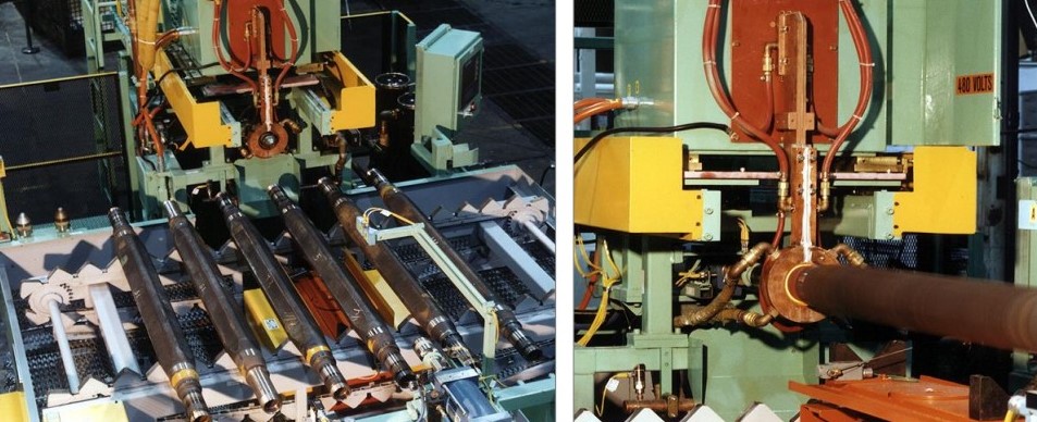
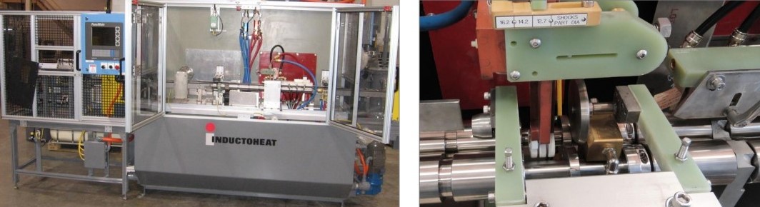
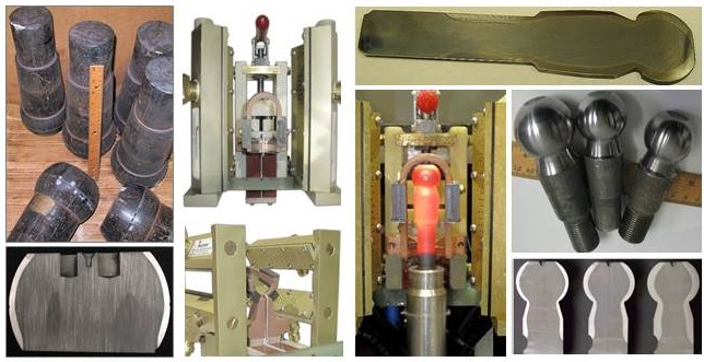
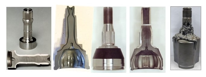
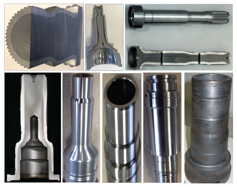
Single-shot inductors can be successfully used for hardening not only components of classical cylinder geometries but other geometries as well. This includes workpieces of general conical shapes, such as elliptic, parabolic, hyperbolic geometries—and the list can grow. As an example, Figure 1 shows induction surface-hardened ball joints (ball studs) and the single-shot inductors used to harden them. Ball studs are used in automotive, off-road, and agricultural machinery and can be different in shape and size (Compare images on the left in Figure 1 with images on the right.), requiring noticeably different hardness patterns.

Figure 1. Surface-hardened ball joints (ball studs) and single-shot inductors used for its hardening. (Courtesy of Inductoheat Inc., an Inductotherm Group company.)

In any attempt to scan harden workpieces with appreciable diameter changes, the scan coil must have a sufficient gap to clear the largest diameter. When scanning the section(s) of the workpiece with smaller diameters, an inductor-to-shaft air gap might be very large, resulting in low electrical efficiency and potentially exhibiting difficulties in load matching as well as in controlling the austenitizing pattern along the length of the part producing "cold" and "hot" spots. Additional difficulties may appear in controlling the hardness pattern in regions (e.g., near geometrical irregularities) where good control is most needed.

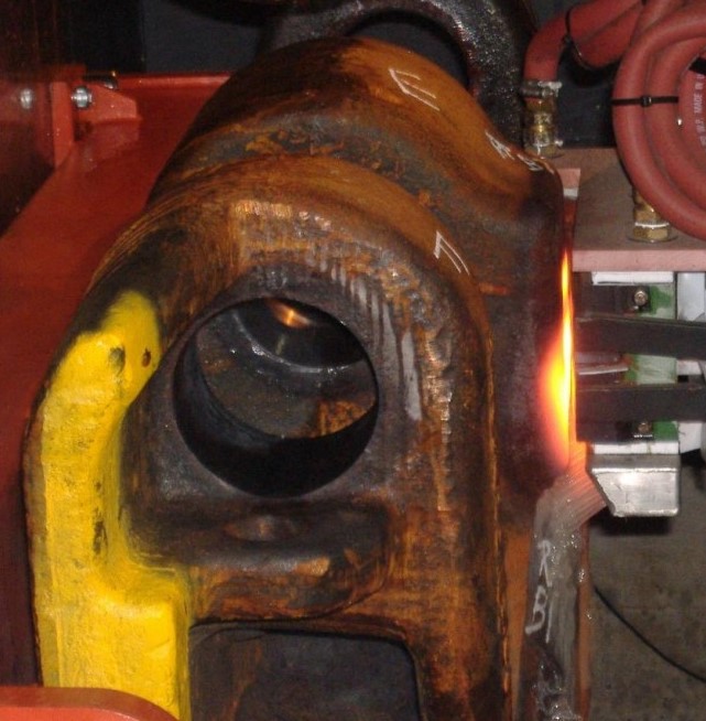
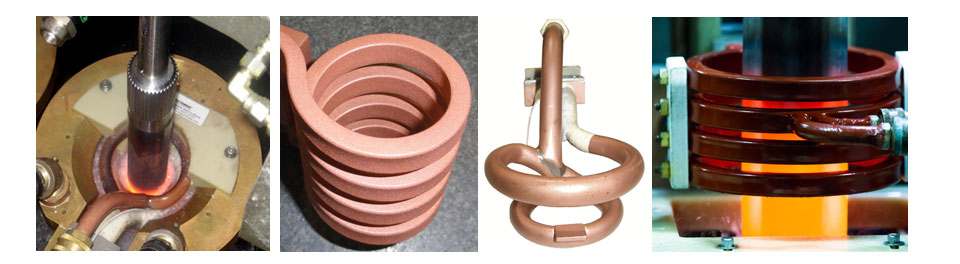
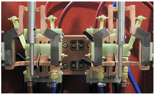
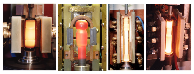
Thus, the substantially different workpiece-to-inductor electromagnetic coupling variations might not permit using classical multiturn solenoid coils or scan inductors. In contrast, single-shot inductors allow not only better electromagnetic coupling along the entire length of heat treated components (Figure 2) but also better address the geometrical irregularities of heat treated workpieces, producing the required hardness patterns at minimum process times with superior metallurgical quality.

Figure 2.  Single-shot inductors allow better electromagnetic coupling along the length of heat treated components properly addressing the geometrical complexity of the workpiece. (Courtesy of Inductoheat Inc., an Inductotherm Group company.)

As stated in Part 1 of this series, in contrast to scan hardening, a single-shot inductor can be contoured along the length of the part properly addressing the geometrical complexity of the workpiece. Furthermore, the use of flux concentrators helps drive the current into the desired areas and allows producing a well-defined hardness profile with minimum distortion. The trade-off here is that more finesse is required in the design stage to produce the properly profiled single-shot inductor at the lowest possible cost.¹ Errors are costly since these inductors are each custom made for a given part or application and modifications can be quite costly. Thus, computer modeling is a helpful assistant as an attempt to keep the development cost down and shorten the "learning curve".

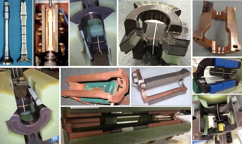
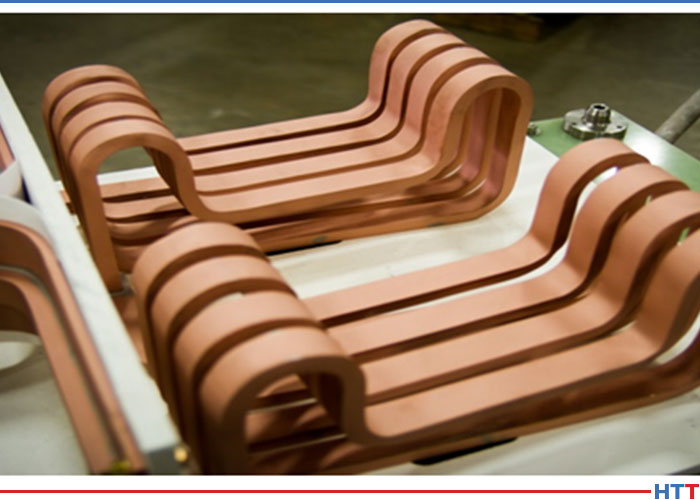
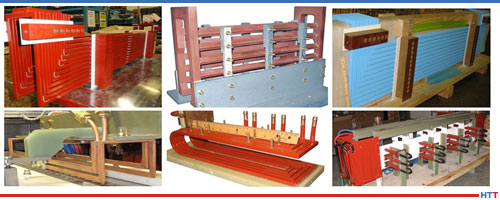
Proper hardening of such components as output shafts, flanged shafts, planet carriers, yoke shafts, sun shafts, intermediate shafts, driveshafts, turbine shafts, and some others may require extensive copper profiling, making a single-shot hardening inductor a complex electromagnetic device.

Certain geometrical features such as flanges, diameter changes, bearing shoulders, grooves, undercuts, splines, etc., may distort the mag­netic field generated by an inductor, which, in turn, can cause tem­perature deviations, making it challenging to achieve certain hardness patterns.

For components containing fillets, it is often necessary to increase the heat intensity in the fillet region owing to the geometrical specifics. Also, the larger mass of metal in the proximity of the heated fillet and behind the region to be hardened produces a substantial thermal “cold sink” effect.¹ This draws heat from the fillet due to thermal conduction, which must be compensated for by generating additional heating energy in the fillet area.

Needed energy surplus can be achieved by narrowing the current-carrying face of the crossover segment of the single-shot inductor (Figure 3). Here is a simplified illustration of an impact of a copper profiling of the inductor’s heating face: if the current-carrying portion of the inductor heating face is reduced by 50 percent, there is a corresponding increase in current density. This will be accompanied by an increase of the eddy current density induced within the respective region. According to the Joule effect, doubling the induced eddy current density increases the induced power density roughly by a factor of four. Also, attaching a magnetic flux concentrator to certain areas of the hardening inductor further enhances the localized heat intensity.

Figure 3.  Longitudinal leg sections of single-shot indicators and their crossover segments can be profiled by relieving selected regions of the copper to accommodate workpiece geometrical features. Attaching a magnetic flux concentrator to certain areas of the inductor further enhances localized heat intensity. (From V. Rudnev, A. Goodwin, S. Fillip, W. West, J. Schwab, S. St. Pierre, Keys to long-lasting hardening inductors: Experience, materials, and precision, Adv. Mater. Processes, October 2015, pp. 48–52.)

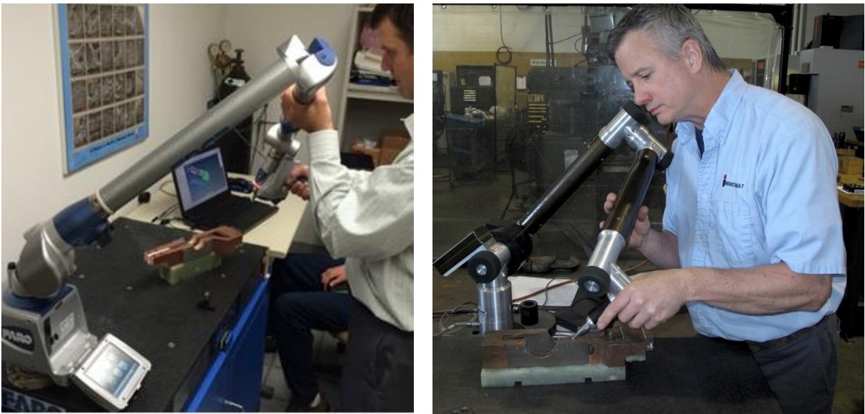
When using a single-shot inductor, it is particularly important that the workpiece is properly located in the heating position because seemingly minor dislocations may noticeably affect the heat treat pattern and metallurgical quality of hardened parts.

Traditionally designed single-shot inductors may exhibit high process sensitivity that is associated with the electromagnetic proximity effect.¹ A change in positioning of the workpiece inside the single-shot inductor attributed to excessive bearing wear of the centers, improper machining of the centers and fixtures, incorrect part loading, and other factors may produce a correspondent appreciable variation in the hardness pattern (particularly within the fillet region, undercut areas, and the part’s end zone). A reduced hardness case depth and the formation of unwanted microstructural products associated with incomplete phase transformation may be the result of that. Magnitude and distribution of transient and residual stresses might also be altered. Thus, attention should be paid to part’s reliable positioning during heating and quenching cycles.

As can be concluded, there are good reasons for using single-shot hardening, scan hardening, or continuous/progressing hardening approaches in induction hardening applications. The decision must be well thought out based on many factors such as geometry specifics, product quality, production rate, design proficiency, limitations of available equipment, reliability requirements, cost considerations, and some other factors.

The next installment of this series, Dr. Valery Rudnev on .  . . , will continue the discussion on design features of induction single-shot hardening systems.


References

  1. V.Rudnev, D.Loveless, R.Cook, Handbook of Induction Heating, 2nd Edition, CRC Press, 2017.
  2. V.Rudnev, "Dr. Valery Rudnev on . . . Equipment Selection for Induction Hardening: Single-Shot Hardening, Part 1", Heat Treat Today, July 9, 2019.
  3. V.Rudnev, A.Goodwin, S.Fillip, W.West, J.Schwab, S.St.Pierre, "Keys to long-lasting hardening inductors: Experience, materials, and precision", Adv. Mater. Processes, October 2015, pp. 48–52.
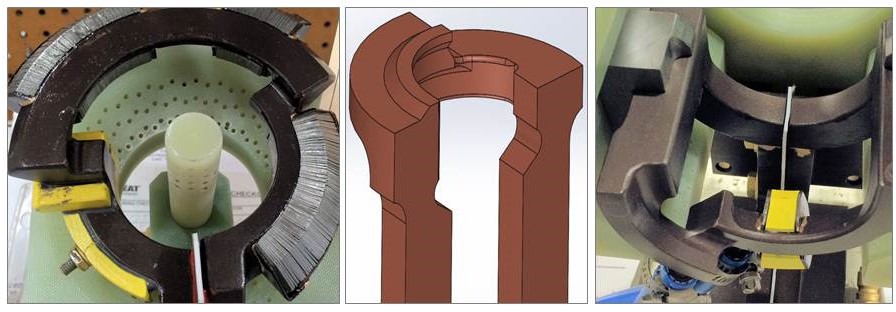
Dr. Valery Rudnev on Equipment Selection for Induction Hardening: Single-Shot Hardening, Part 3 Read More »

Dr. Valery Rudnev on Equipment Selection for Induction Hardening: Single-Shot Hardening, Part 2

This article continues the ongoing discussion on Equipment Selection for Induction Hardening by Dr. Valery Rudnev, FASM, IFHTSE Fellow. Six previous installments in Dr. Rudnev’s series on equipment selection addressed selected aspects of scan hardening and continuous/progressive hardening systems. This post is the second in a discussion on equipment selection for one of four popular induction hardening techniques focusing on single-shot hardening systems.

The first part on equipment selection for single-shot hardening is here; the third part is here. To see the earlier articles in the Induction Hardening series at Heat Treat Today as well as other news about Dr. Rudnev, click here


Traditional Designs of Single-Shot Inductors

Figure 1 shows a typical shaft-like component (Figure 1,top-left) suitable for a single-shot hardening inductor, as well as a variety of traditionally designed single-shot inductors for surface hardening shaft-like workpieces. Sometimes, these inductors are also referred to as channel inductors.

A conventional single-shot inductor consists of two legs and two crossover segments, also known as bridges, “horseshoes,” or half-loops [1]. The induced eddy currents under the legs primarily flow along the length of the part (longitudinally/axially) with the exception of the regions of the workpiece located under the crossover segments where the flow of the eddy current is half circumferential. Unlike scanning inductors, traditional designs of single-shot inductors can be quite complicated.

Figure 1. A typical shaft-like component (top-left image) suitable for a single-shot hardening and a variety of traditionally designed single-shot inductors for surface hardening shaft-like workpieces (Courtesy of Inductoheat Inc., an Inductotherm Group company)

With a predominantly longitudinal eddy current flow, the heat uniformity in the diameter change areas of the stepped shafts is dramatically improved and the tendency of corners and shoulders to be overheated is reduced significantly compared to applying a single-turn or multi-turn solenoid coils commonly used in scan hardening and continuous/progressive hardening.

Because the copper of single-shot inductors does not completely encircle the entire region required to be heated, rotation must be used to create a sufficiently uniform austenitized surface layer along the workpiece perimeter. Upon quenching, a sufficiently uniform hardness case depth along the circumference of the part will be produced. For single-shot inductors, the rotation speed usually ranges from 120 to 500 rpm.

Different types of magnetic flux concentrators (also called flux intensifiers, flux controllers, flux diverters, magnetic shunts, etc.) complement the copper profiling of an inductor, helping to achieve the required hardness pattern. Flux concentrators may provide several considerable benefits when applied in single-shot inductors. This includes an increase of coil electrical efficiency, a noticeable reduction of coil current, and a significant reduction of the external magnetic field exposure.

As an example, Figure 2 shows a transverse cross-section of a single-shot inductor and a straight shaft. Computer-modeled electromagnetic field distribution of a bare inductor (Figure 2, left) compared to an inductor with a U-shaped flux concentrator (Figure 2, right) is shown. Note that the magnitude of magnetic field intensity on both images is different. The use of U-shaped magnetic flux concentrators in single-shot hardening applications typically results in a 16% to 27% coil current reduction compared to using a bare inductor while having a similar heating effect. A reduction of the external magnetic field exposure while applying flux concentrator is even more dramatic (Figure 2, right).

Figure 2.  Computer-modeled EMF distribution in the transverse cross-section of a bare inductor (left) compared to an inductor with U-shaped flux concentrator (right). Note: the scale of magnetic field intensity on both images is different [1].
Different applications may call for various materials used to fabricate magnetic flux concentrators including stacks of silicon-steel laminations, pure ferrites, and various proprietary multiphase composites. The selection of a particular material depends on a number of factors, including the following [1]:

  • applied frequency, power density, and duty cycle;
  • operating temperature and ability to be cooled;
  • geometries of workpiece and inductor;
  • machinability, formability, structural homogeneity, and integrity;
  • an ability to withstand an aggressive working environment resisting chemical attack by quenchants and corrosion;
  • brittleness, density, and ability to withstand occasional impact force;
  • ease of installation and removal, available space for installation, and so on.

It should be noted that, though in most single-shot hardening applications flux concentrators will improve efficiency, there are other cases where no improvement will be recorded, or efficiency may even drop. A detailed discussion regarding the subtleties of using magnetic flux concentrators is provided in [See References 1, 2.].

Sufficient rotation is critical when using any single-shot inductor design. As an example, Figure 3 shows the sketch of a single-shot induction hardening system.

Figure 3.  Sketch of single-shot induction hardening of an axle shaft. Note: The right half of this induction system is computer-modeled in Fig. 4 [3].
Taking advantage of symmetry, only the right side of such a system was modeled using finite-element analysis. Figure 4 shows the result of computer simulation of initial, interim, and final heating stages, taking into consideration the shaft rotation. Insufficient part rotation resulted in a non-uniform temperature distribution along the shaft perimeter (Figure 4, left). Proper shaft rotation results in a sufficiently uniform temperature pattern (Figure 4, right).

Figure 4.  Results of numerical simulation of heating an axle shaft by using a single-shot inductor [3].
There should be at least eight full rotations per heat cycle (preferably more than 12 rotations), depending on the size of the workpiece and the design specifics of the inductor, though, as always in life, there are some exceptions. Shorter heating times and narrower coil copper heating faces require faster rotation during the austenitization cycle.

An appropriate inductor design with a closely controlled and monitored rotation speed will produce a hardness pattern with minimum circumferential and longitudinal temperature deviations, which will result in sufficiently uniform hardness patterns (Figure 5, left four images). Failure to ensure proper rotation as well as the use of worn centers (lacking grabbing force resulting in slippage and excessive part wobbling) could lead to an unacceptable heat non-uniformity, severe local overheating, and even melting (Figure 5, right). Manufacturers of induction equipment such as Inductoheat have developed various proprietary tools, holders, fixtures, and monitoring devices to ensure proper rotation and high quality of single-shot hardened parts.

Figure 5.  Inductor design with closely controlled rotation speed will produce a hardness pattern with minimum circumferential temperature deviations (left four images). Failure to ensure proper rotation speed as well as the use of worn centers (lacking grabbing force resulting in slippage) could lead to unacceptable heat non-uniformity and can even cause a localized melting (right image).

The next installment of this column, "Dr. Valery Rudnev on . . . ", will continue the discussion of design features of induction single-shot hardening systems.

References

  1. V.Rudnev, D.Loveless, R.Cook, Handbook of Induction Heating, 2nd Edition, CRC Press, 2017.
  2. V.Rudnev, "An objective assessment of magnetic flux concentrators", Heat Treating Progress, ASM Intl., December 2004, pp 19-23.
  3. V.Rudnev, "Simulation of Induction Heat Treating", ASM Handbook, Volume 22B, Metals Process Simulation, D.U. Furrer and S.L. Semiatin, editors, ASM Int’l, 2010, pp 501-546.


Dr. Valery Rudnev on Equipment Selection for Induction Hardening: Single-Shot Hardening, Part 2 Read More »

Dr. Valery Rudnev on . . . Equipment Selection for Induction Hardening: Single-Shot Hardening, Part 1

This article continues the ongoing discussion on Equipment Selection for Induction Hardening by Dr. Valery Rudnev, FASM, IFHTSE Fellow. Six previous installments in Dr. Rudnev’s series on equipment selection addressed selected aspects of scan hardening and continuous/progressive hardening systems. This post continues a discussion on equipment selection for induction hardening focusing on single-shot hardening systems.

The first part on equipment selection for continuous and progressive hardening is here. The second part in this series on equipment selection for single-shot hardening is here; the third part is here. To see the earlier articles in the Induction Hardening series at Heat Treat Today as well as other news about Dr. Rudnev, click here. This installment continues a discussion on equipment selection for continuous and progressive hardening applications.


Why Single-Shot Hardening?

With the single-shot method, neither the workpiece (cylinder shaft, for example) nor the coil moves linearly relative to each other; the part typically rotates instead.¹ The entire region that is to be hardened is heated all at once rather than only a short distance, as is done with scan hardening.

With conventional scan hardening of cylindrical parts, induced eddy currents flow circumferentially. In contrast, a single-shot inductor induces eddy currents that primarily flow along the length of the part. An exception to this rule would be the half-moon regions (also called the crossover or bridge sections) of a single-shot inductor, where eddy current flow is circumferential.

Normally the single-shot method is better suited for hardening stepped parts where a relatively short (1.5–2 in. [38–50mm] long heated area is commonly minimum) or moderate length area is to be heat treated. This method is also better suited to cylindrical parts having axial symmetry and complex geometry including various diameters.

When scanning these types of parts, improper austenitization of certain areas may occur due to localized electromagnetic field distortion, for example. Insufficient quenching due to the deflection of quench flow not allowing it to properly impinge on the surface in various diameter regions may also occur. Both factors are considered undesirable and can cause low hardness, spotted hardness, or even cracking. For example, the use of scan hardening on stepped shafts with large shoulders, multiple and sizable diameter changes, and other geometrical irregularities and discontinuities (including fillets, flanges, undercuts, grooves, etc.) may produce severely non-uniform hardened patterns. In cases like this, a scan hardening inductor or progressive/continuous hardening system would be designed around the largest diameter that would have sufficient clearance for safe part processing.¹ However, variations in the shaft’s diameter, to a significant extent, will result in a corresponding substantial deviation in the workpiece-to-coil coupling in different sections of the shaft, potentially causing irregular austenization.

Besides that, sharp corners have a distinct tendency to overheat owing to the buildup of eddy currents, in particular when medium and high frequencies are used. The electromagnetic end and edge effects may also cause the shoulders to severely overheat while the smaller-diameter area near the shoulder (including undercuts and fillets) may have noticeable heat deficit. These factors may produce a hardness pattern that might grossly exceed the required minimum and maximum case depth range, making it unacceptable. Single-shot hardening is usually a better choice in such applications. As an example, Figure 1 shows some examples of components for which single-shot hardening would be a preferable method of heat treating.

Examples of components for which a single-shot hardening would be a preferable method of heat treating. (Courtesy of Inductoheat Inc., an Inductotherm Group company)


In some not so frequent cases, when hardening larger parts, there are advantages to the single-shot method over the scanning method, such as the reduction of shape/size distortion, enhanced metallurgical quality, and increased production rate.

Single-shot hardening may also be the preferred choice when shorter heat times/high production rates are desired. For example, in some applications, the time of heating for single-shot hardening can be as short as 2 s, though 4 to 8 s is more typical.

However, the single-shot method has some limitations as well. One of them is cost. Single-shot inductors are typically more expensive to fabricate compared to the coils used for scanning. This is because the single-shot inductor, to some degree, must follow the contour of the entire region required to be heated. Additionally, a single-shot inductor is usually able to harden only one specific part configuration, whereas a coil used for scanning may be able to harden a family of parts.

Besides that, in some case hardening applications using a scanning method, it is possible to apply certain pre-programmed pressure/force on a workpiece during heat treating. This allows distortion to be controlled. Single-shot hardening might also permit applying this technique but there might be some limitations.

Design Features of Single-Shot Inductors

Single-shot inductors are made of tubing, either 3-D printed or CNC-machined from solid copper to conform to the area of the part to be heated. This type of inductor requires the most care in fabrication because it usually has an intricate design and operates at high power densities, and the workpiece’s positioning is critical with respect to the coil copper profiling. Figure 2 shows several examples of induction heating of different components using single-shot inductors.

Several examples of induction heating of different components using single-shot inductors. (Courtesy of Inductoheat Inc., an Inductotherm Group company)


In order to provide the required temperature distribution before quenching, heat is sometimes applied in several short bursts (pulse heating) with a timed delay/soaking between them to allow for thermal conduction toward the areas that might be difficult to heat.

Single-shot inductors typically require higher power levels than used in scan hardening because the entire area of the workpiece that needs to be hardened is austenitized at once. This is the reason why single-shot hardening normally requires having a noticeably larger power supply compared to scan hardening, resulting in increased capital cost of power source. Additionally, the increased power usage and power densities combined with complex geometry can reduce the life of the inductor. For this reason, single-shot inductors often have shorter lives than scan inductors.

It is always important to keep in mind that, electrically speaking, the inductor is typically considered the weakest link in an induction system. For this reason, most single-shot inductors have separate coil-cooling and part-quenching circuits. The inductor will fail if power is increased to the point at which the water cannot adequately cool it. Additional cooling passages may be needed with high-power density, single-shot inductors. A high-pressure booster pump is also frequently required.

The next several installments of Dr. Valery Rudnev on . . . will continue the discussion on design features of single-shot inductors and equipment selection.


References

  1. Rudnev, D.Loveless, R.Cook, Handbook of Induction Heating, 2nd Edition, CRC Press, 2017.


Dr. Valery Rudnev on . . . Equipment Selection for Induction Hardening: Single-Shot Hardening, Part 1 Read More »

Dr. Valery Rudnev, FASM, IFHTSE Fellow, Honored To Deliver Heat Treat Lecture

Dr. Valery Rudnev, FASM, IFHTSE Fellow, was selected to be the Woodside lecturer at the most recent ASM Detroit Chapter meeting. The Woodside lecture took place on May 13, 2019, at Burton Manor in Livonia, Michigan. The title of the lecture was “Recent Theoretical and Practical Novelties in Induction Heat Treatment“.

Dr. Rudnev serves as Director of Science and Technology at Inductoheat, Inc. Known within the ASM Int’l and among induction heating professionals as “Professor Induction” for his 40+ years of experience in the heat treating industry, Dr. Rudnev centered his Woodside lecture on recent theoretical and practical novelties in induction heat treatment. He also unveiled common mispostulations associated with induction heating and frequently overlooked metallurgical subtleties.

Thermal processing by means of electromagnetic induction continues to grow at an accelerated rate, replacing alternative processes. Today’s metalworking and heat treating industry must quickly adjust to a rapidly changing business environment, maximizing cost effectiveness, process flexibility, and energy efficiency, yet satisfy continuously increasing demands for higher-quality products, equipment longevity, and environmental friendliness.

Induction heating is a multifaceted phenomenon comprising a complex interaction of electromagnetics, heat transfer, circuit analysis, power electronics and metallurgical phenomena that are tightly interrelated. Novel designs have appeared quite regularly.

The Woodside Lecture is named after William P. Woodside, who founded the American Society for Materials (ASM Int’l.) in Detroit in 1913. Each year, the chapter honors an outstanding member of
the ASM community by asking them to give the annual Woodside Lecture.

Dr. Rudnev holds more than 50 patents and inventions (U.S.and International) and has appeared in more than 250 engineering/scientific publications. He also frequently contributes content to Heat Treat Today. His most recent series, “Equipment Selection for Induction Hardening: Continuous and Progressive Hardening” can be found on Heat Treat Today’s website or in Heat Treat Today’s quarterly print editions.


Photo Caption: (from left-to-right)  Dr. Robert C. McCune, FASM (Tech Chair of this event), Dr. James Boileau, ASM Detroit Chair 2018-19, and Dr. Valery Rudnev, FASM, IFHTSE Fellow (the Woodside Lecturer)

Dr. Valery Rudnev, FASM, IFHTSE Fellow, Honored To Deliver Heat Treat Lecture Read More »

Dr. Valery Rudnev on … Equipment Selection for Induction Hardening: Continuous and Progressive Hardening, Part 3

This article continues the ongoing discussion on Equipment Selection for Induction Hardening by Dr. Valery Rudnev, FASM, IFHTSE Fellow. Dr. Rudnev previously reviewed equipment selection for scan hardening in three parts. The first part on equipment selection for continuous and progressive hardening is here; the second part is here. To see the earlier articles in the Induction Hardening series at Heat Treat Today as well as other news about Dr. Rudnev, click hereThis installment continues a discussion on equipment selection for continuous and progressive hardening applications.


Inductor Designs

So far, I have discussed the application of conventionally designed solenoid coils in continuous/progressive hardening applications. However, even multiturn solenoid-type coil geometries may have quite complex shapes accommodating the shape of induction hardened components. One illustration of this is shown in Figure 1 where two in-line multiturn solenoid-type inductors are used for heat treating of an irregular shape component.

Figure 1. Two in-line multiturn solenoid inductor of a complex shape. (Courtesy of Inductoheat Inc., an Inductotherm Group company)

Besides multiturn solenoid coils, channel-type multiturn inductors (also called slot or skid inductors) are frequently used in continuous/progressive heat treating. The channel inductor gets its name from its similarity to a long channel. This shape allows parts to be passed through the coil in a number of ways, such as a conveyor, shuttle, indexing, rotary or carousel table, turntable, or any other indexing system.

Channel coils permit easy entry and exit of the heated components to/from the inductor. Figure 2 shows images of some examples of multiturn channel inductors. The crossover ends of channel coils are bent away to allow the part to pass through. In some cases, the crossover ends are made high enough to ensure minimum impact on the heating of the part at the ends of the coil, minimizing electromagnetic forces when workpieces enter and exit the inductor. In other cases, the opposite might be true, and crossover coil regions play an important part in providing the needed temperature distribution.

Figure 2. Images of different examples of multiturn channel inductors. (Courtesy of Inductoheat Inc., an Inductotherm Group company.)

Channel coils are used to heat treat selected regions of parts, as well as entire components. These inductors are often used for through hardening, annealing, and tempering applications. However, if a specific case depth is required, rotation of the workpiece may be needed to even case depth.

Figure 3 shows a “state-of-the-art” continuous fed induction system for heat treating fasteners [2]. This system is adjustable for a wide range of fastener/bolt diameters and lengths (0.5–4.0 in. [12–102 mm]) and is capable of production rates of up to 600 fasteners per minute. The unique proprietary coil design developed by Radyne Corporation maximizes electrical efficiency and system flexibility while preventing stray heating of electrically conductive surroundings that may potentially cause undesirable heating of structures and malfunction of electronic devices. The rotary dial tooling is designed to accept bolt fasteners from the in-line vibratory feeder. The adjustable speed rotary table contains advanced safety features to prevent damage and meltdown.

The quench assembly allows adjusting the quench flow for the utmost in quench control. After spray quenching, parts are stripped from the traverse assembly and dunk quenched into the tank for final cooling to room temperature.

Figure 3 shows a “state-of-the-art” continuous fed induction system for heat treating fasteners [2].
The tooling is designed with a quick change feature to ensure that all tooling can be changed for a different part size in less than 15 minutes. The system is controlled through a controls package and HMI for part setup and part storage of different programs. Through this HMI, the power source coil “Z” adjustment can also be stored and adjusted for different bolt lengths assuring superior quality fasteners. This unit includes four sizes of tooling required for the rotary heat treat fixture and the traverse tooling: M6, M8, M10, and M12.

Besides solenoid coils and channel inductors, other inductor styles are used including split-return, hairpin and double hairpin inductors, transverse flux, and traveling wave inductors. However, an application of those inductors is not as frequent for continuous/progressive induction hardening.

References

  1. V.Rudnev, D.Loveless, R.Cook, Handbook of Induction Heating, 2nd Edition, CRC Press, 2017.
  2. J.Mortimer, V.Rudnev, Bernhard,A., Induction Heating and Heat Treating of Fasteners, Fastener International, February, 2019, p.50-53.

Dr. Valery Rudnev on … Equipment Selection for Induction Hardening: Continuous and Progressive Hardening, Part 3 Read More »

Dr. Valery Rudnev on . . . Equipment Selection for Induction Hardening: Continuous and Progressive Hardening, Part 2

This article continues the ongoing discussion on Equipment Selection for Induction Hardening by Dr. Valery Rudnev, FASM, IFHTSE Fellow. Dr. Rudnev previously reviewed equipment selection for scan hardening in three parts. The first part on equipment selection for continuous and progressive hardening is here; the third part is here. To see the earlier articles in the Induction Hardening series at Heat Treat Today as well as other news about Dr. Rudnev, click here


Frequency Selection

Depending on the application specifics, continuous and progressive hardening lines may use the same frequency for various in-line coils. In other cases, power levels and frequencies may be different at different heating positions. The presence of three general process stages (described in Part 1) makes a marked impact on a selection of process parameters and the design of an induction system.

When using different frequencies for the various heating stages, the coil design may need to change as well (e.g., a number of coil turns may need to be adjusted for load matching purpose). Just as the eddy current penetration depth in the heated part is affected by the frequency, the current flow in the inductor is affected as well. The wall thickness of the inductor turns (i.e., copper tubing wall) might need to be adjusted to accommodate different frequencies to maximize the coil electrical efficiency.¹

The wall thickness of an inductor’s heating face should be increased as frequency decreases. It is highly desirable for the current-carrying copper wall thickness to be 1.6 times greater than the current penetration depth in the copper (δCu). Increased kilowatt losses in the copper, which are associated with reduced electrical efficiency and greater water-cooling requirements, will occur if the wall is thinner than 1.6∙δCu. In some cases, the copper wall thickness can be noticeably thicker than the recommended value of 1.6∙δCu. This is because it may be mechanically impractical to use a tubing wall thickness of, for example, 0.25 mm (0.01 in.).

As an example, Figure 1 shows a number of continuous in-line multi-coil systems for induction heat treating wire products.²

Several continuous in-line systems for heat treating wire products (Courtesy of Radyne Corp., and Inductotherm Heating & Welding, UK. Both are Inductotherm Group companies.)

There are noticeable benefits of compact induction systems compared to fluidized beds, infrared heaters, and gas furnaces, such as quick response and the ability to provide a rapid change in the process operating parameters to accommodate the required temperature of the wire/cable being processed at speeds up to 5 mps. Frequencies that are in the range of 10 to 800 kHz are commonly applied. A dual-frequency concept can be beneficial to enhance electrical efficiency of while heating different diameters/thicknesses or it can be advantageous for through heating of metallic alloys that exhibit low toughness/high brittleness.

According to the dual-frequency concept, a lower frequency is used during the initial heating stage when the steel is magnetic. In the final heating stage, when the steel becomes nonmagnetic with significantly increased current penetration depth δsteel and becomes substantially more ductile, it is beneficial to use a higher frequency.

Case study¹:

As an example, consider the induction heating of a 1/8 inch-diameter (3.2 mm-diameter) steel rod from ambient to 2000°F (1100°C) using both a single 10-kHz frequency and dual 10-kHz/200-kHz frequencies (see Figure 2). When using the single frequency of 10 kHz (Figure 2, left), the rod’s final temperature experiences very little change regardless of the coil power that is increased more than fivefold (from 17 to 90 kW). The only noticeable difference is related to the initial slope of the temperature-time curve, where the steel is ferromagnetic. Upon reaching the Curie point, there is no noticeable temperature rise. This is the result of severe eddy current cancellation making the steel rod transparent (practically speaking) to the electromagnetic field of the induction coil.

Illustration of the dual-frequency concept when induction heating a 1/8 inch-diameter (3.2 mm-diameter) carbon steel rod from room temperature to 2012°F (1100°C) using both a single frequency of 10 kHz (a) and dual frequencies of 10 kHz/200 kHz (b). (Source: V.Rudnev, Systematic analysis of induction coil failures, Part 11c: Frequency selection, Heat Treating Progress, January/February, ASM Intl., 2008, pp. 27–29.)

In contrast, Figure 2, right, shows that a dual-frequency approach provides a remarkable improvement in the ability to heat the rod above the Curie temperature. A power of 14 kW/10 kHz was used to heat the rod below the Curie point and a power of 19 kW/200 kHz was used above it. The total required power is only 33 kW, compared with 90 kW using just 10 kHz, which was still unable to provide the required temperature rise.

Note: The target temperature of 2000°F (1100°C) is above typical target temperatures when hardening plain carbon or low alloy steels and it is more suitable for hot forming applications. This temperature was selected here to better illustrate a dual-frequency concept and the importance of avoiding eddy current cancellation when choosing operating electrical frequencies. It should be noted though that it is not unusual that the heat treating protocols/recipes for some alloyed steels and stainless steels may require target temperatures of 1900°F to 2100°F (1050°C to 1150°C) range.

In some not too often cases, three frequencies may be used. Lower frequency is applied for preheating inductors, a medium frequency is used for mid-heat inductors, and a high frequency is used for final heat inductors.

Sometimes, it is required that the induction system should be able to heat a variety of sizes using a single frequency. In these cases, in order to provide efficient steel heating, it is necessary to choose a frequency that will guarantee that the “diameter-to-current penetration depth (δsteel)” ratio exceeds 3.6 for any workpiece diameter or heating stage. Thus, it is important to remember that when calculating δsteel, the values of electrical resistivity and relative magnetic permeability of the heated material should correspond to their values at the highest temperature that occurs during the entire heating cycle.

The next installment of this column will review a variety of styles of inductors used in continuous and progressive induction hardening applications.


References

  1. V.Rudnev, D.Loveless, R.Cook, Handbook of Induction Heating, 2nd Edition, CRC Press, 2017.
  2. J.Mortimer, V.Rudnev, D.Clowes, B.Shaw, “Intricacies of Induction Heating of Wires, Rods, Ropes, and Cables”, Wire Forming, Winter, 2019, p.46-50

Dr. Valery Rudnev, FASM, IFHTSE Fellow, is the Director of Science & Technology, Inductoheat Inc., and a co-author of Handbook of Induction Heating (2nd ed.), along with Don Loveless and Raymond L. Cook. The Handbook of Induction Heating, 2nd ed., is published by CRC Press. For more information click here.

Dr. Valery Rudnev on . . . Equipment Selection for Induction Hardening: Continuous and Progressive Hardening, Part 2 Read More »

Dr. Valery Rudnev on . . . Equipment Selection for Induction Hardening: Continuous & Progressive Hardening, Part 1

This article continues the ongoing discussion on Equipment Selection for Induction Hardening by Dr. Valery Rudnev, FASM, IFHTSE Fellow. Previously, Dr. Rudnev reviewed equipment selection for scan hardening in three parts. This first installment in a new sub-series addresses equipment selection for continuous and progressive hardening. The second part in this series on equipment selection for continuous and progressive hardening is here; the third part is here. To see the earlier articles in the Induction Hardening series at Heat Treat Today as well as other news about Dr. Rudnev, click here


Introduction

The hardening of steels, cast irons, and P/M materials represent the most popular application of induction heat treatment. There are four primary methods for induction hardening [1]:

  • Scan hardening,
  • Continuous and progressive hardening,
  • Static hardening, and
  • Single-shot hardening.

These methods are related to the heating mode, essentials of inductor design, part geometry, and processing specifics. The previous three installments of this column, “Dr. Valery Rudnev on …”, discussed select subtleties associated with induction scan hardening. This article is devoted to continuous and progressive induction hardening techniques.

Continuous and Progressive Hardening

This method is commonly applied when heat treating elongated workpieces, such as bars, tubes, rods, wires, plates, beams, pins, and others. Long parts are more readily processed in a horizontal manner and heated as they progressively pass through multiple inductors. Inductors are positioned in-line or side by side. Each inductor may have a different design and power/frequency setting. This type of hardening is not limited to horizontally processed parts; vertical processing and arrangements at certain angles are also possible, if suitable.

There are also cases when a workpiece is statically heated to a certain temperature and then progressively moved to another heating position or static inductor for the next heating stage. These processes are referred to as progressive processing/heat treatment.

Induction practitioners sometimes consider continuous or progressive horizontal hardening systems as horizontal scanners. The difference is vague and it is a matter of terminology. Some heat treaters feel that it would be appropriate to differentiate these systems based on the number of inductors included in the induction machine design. Horizontal systems consisting of a single inductor are commonly referred to as horizontal scanners. In contrast, if a system consists of two or more heat treat inductors, then it might be referred to as a continuous or progressive heat treat system.

With the continuous hardening method, the workpiece is moved in continuous motion through a number of in-line inductors. Multiturn solenoid coils and, to lesser a degree, channel-style inductors and split-return inductors are most typically used in continuous heat treating lines. As an example, Figure 1 shows a side view of a horizontally arranged continuous induction system consisting of three in-line coils. Each coil consists of three turns.

Figure 1

As another example, Figure 2 shows a top view of a continuous heat treating line that comprises four in-line hardening coils and a spray quench device positioned after the last inductor. Workpieces (e.g., bars, shafts, rods, pins, etc.) are processed end-to-end through the inductors in a continuous motion.

Figure 2

Progressive multi-stage hardening is used when multiple workpieces are moved (via a pusher, indexing mechanism, robot, walking beam, etc.) through a number of coils. Therefore, the entire component or its portions are sequentially heated (in a progressive manner) at certain predetermined heating stages inside the in-line horizontal (being more typical) induction heater or a multi-position horizontal or vertical heater where coils are positioned side by side.

Continuous or progressive hardening methods are typically used for through hardening of elongated or moderate-length parts processing end to end and, to a lesser degree, for surface hardening. Outside diameters for case hardening (surface hardening) usually vary from 1/2 in. (12 mm) to 4 in. (100 mm). In through hardening applications of solid cylinders, the diameters may be as small as 1/8 in. (3 mm).

It is possible to recognize three heating stages in through hardening applications [1]:

  1. Initial or magnetic stage,
  2. Interim stage, and
  3. Final heating stage.

Initial or magnetic stage. Temperatures anywhere within the workpiece are below the A2 critical temperature (Curie point); thus, the steel is ferromagnetic and the current penetration depth is typically quite small. Skin effect is fairly pronounced at this stage and the heat source distribution resembles a conventional exponential distribution. The maximum power density is located at the surface and sharply decreases toward subsurface and the core. Heat source generation is localized by the fine surface layer of the workpiece. This leads to a rapid increase in temperature at the surface with a minor change in the core. This stage is characterized by high electrical efficiency often reaching 90% or so.

Interim stage. During this stage, the austenized surface layer and near-surface area is heated above the A2 critical temperature; however, the internal region, having temperatures below the Curie point, retains its ferromagnetic properties. At this stage, the power density distribution along the radius has a unique non-exponential “wave-like” distribution, which is very different from the commonly assumed exponential distribution. The cause for this behavior has been explained in Ref.1.

Final heating stage. The thickness of the austenized surface layer that exhibits nonmagnetic properties becomes greater than the current penetration depth in hot steel at a given frequency, and the “wavelike” distribution disappears. The classical exponential power density distribution will then take place. As expected, heat source generation depth has increased dramatically compared to an initial stage resulting in a more in-depth heating effect. With time, the core temperature exceeds the Curie point and the entire cross section will be nonmagnetic.

In surface hardening applications, there are typically only the first two heating stages.

Depending on the application specifics, the same frequency may be used for various coils or process stages. In other cases, power levels and frequencies may vary at the different heating stages. The presence of above-described process stages makes a marked impact on a selection of process parameters and design of an induction system and will be discussed in the next installment of this column.

References

1. V. Rudnev, D. Loveless, R. Cook, Handbook of Induction Heating, 2nd Edition, CRC Press, 2017.


Dr. Valery Rudnev, FASM, IFHTSE Fellow, is the Director of Science & Technology, Inductoheat Inc., and a co-author of Handbook of Induction Heating (2nd ed.), along with Don Loveless and Raymond L. Cook. The Handbook of Induction Heating, 2nd ed., is published by CRC Press. For more information click here.

Dr. Valery Rudnev on . . . Equipment Selection for Induction Hardening: Continuous & Progressive Hardening, Part 1 Read More »

Dr. Valery Rudnev on Equipment Selection for Scan Hardening, Part 3

Dr. Valery Rudnev on . . . 

Induction Hardening Tips: Equipment Selection for Scan Hardening, Part 3

This is the third installment of a multi-part column on equipment selection for induction heat treatment. Part 1, Dr. Valery Rudnev On . . . Induction Hardening Tips: Equipment Selection for Scan Hardening, covered types of scanners, scan hardening system setup, quenching challenges, maximizing process flexibility, and computer modeling. In Part 2, Dr. Valery Rudnev discussed another critical aspect of induction scan hardening: inductor design subtleties and a comparison of different fabrication techniques (brazing vs. CNC
machining vs. 3D printing).

In this installation, Dr. Rudnev focuses on Moveable Inductor versus Moveable Part.


Moveable Inductor versus Moveable Part

As stated in one of the previous installments of this column, when a scan processing mode is chosen, either the inductor or the part or both may be moved during the heating and quenching. This installment discusses the applicability of those approaches (movable inductor vs. movable part), as well as pros and cons associated with both techniques.

Figure 1. An example of scan hardening of track shoes for earth-moving machines that often specify deep hardness case depths (up to the 24 mm).

The choice to move the inductor or to move the part is primarily based on required production rate as well as on the size, weight, and geometry of the component compared to the size, weight, and geometry of the inductor: in other words, it depends on which of the two is easier to move.

Weight is an important factor because the movement can occur several hundred times each day and, in some cases of high production, even several thousand times per day. For example, during induction surface hardening of track shoes for earth-moving machines that often specify deep hardness case depths (up to 24 mm), it is much easier to move the inductor around the workpiece instead of moving the track shoes, the weight of which can exceed several thousand pounds. (Figure 1)

When moving the inductor, both flexible cables and hoses are used or the inductor is hard-bused to the transformer and the transformer or heat station moves with the inductor. In some cases, the power supply itself may be moved at a moderate rate to scan a stationary workpiece [1]. Another example of moving the inductor is surface hardening of trailer axles. (Figure 2)


Figure 2. (Left image) Horizontal scanner to induction harden both ends of a trailer axle. A walking beam system was incorporated into the machine for part transfer. At the heating station, the axle is lifted off the beam and the power supply and inductor are indexed to position for scan hardening. After the completion of surface hardening of one end, the axle is then lifted off the transfer mechanism and rotated 180° to induction harden the opposite end. Heavy-duty precision shafting and bearings are used for stability and consistency. (Right image) shows a close-up of a movable inductor to scan harden trailer axle ends. Heating time is less than 8 s per axle end.


The length of the part to be heated is also an important consideration When a component is of moderate weight, it is obviously preferable to move the part rather than the inductor. For example, it is much easier and more cost-effective to design a hardening system that anticipates moving a workpiece that weighs less than 0.25 kg (<0.5 lb) rather than moving an entire power supply, as it is shown in Figure 3.

Figure 3. Horizontal scanner that provides a maximum scan rate up to 200 mm/s (8 in./s). (Courtesy of Inductoheat Inc., an Inductotherm Group company.)


In other cases, it may not be practical to move very large and elongated components. It would consume too much floor space to move the part through a stationary inductor. In the case of low production rates, the best choice might be to move the inductor, but the length of the high-frequency power leads could become a problem with respect to voltage drop and power loss. In this case, it is preferable to move the inductor with the power supply attached. Then, the moving cables are operating at a low frequency (50–60 Hz) with lower voltage drop and power loss. In the case of high production, continuous horizontal systems may be more suitable.

The consideration of the length of the leads (e.g., cables or buses) from the power source to the inductor is important. They should be as short as possible to conserve energy and to allow the power source to operate properly without reaching any limits (for example, voltage limit). If these leads are too long, the inductance increase can be so significant that it may result in a substantial power loss and voltage drop. The voltage drop in the leads may even exceed the voltage at inductor’s terminals. Long leads could net an excessive total needed power, a measurable reduction in energy efficiency, and potential concerns regarding the process repeatability owing to the possibility of an appreciable inductance change of the flexible leads during their motion, that in some cases may negatively impact process repeatability.

Whether moving the inductor or moving the part, the induction system can be designed to be efficient and robust in order to ensure smooth and consistent operation and the production of quality parts.

I recommend Reference #1 to readers interested in further reading on this subject.


References

  1. V. Rudnev, D. Loveless, R. Cook, Handbook of Induction Heating, 2nd Edition, CRC Press, 2017.


Dr. Valery Rudnev, FASM, IFHTSE Fellow, is the Director of Science & Technology, Inductoheat Inc., and a co-author of Handbook of Induction Heating (2nd ed.), along with Don Loveless and Raymond L. Cook. The Handbook of Induction Heating, 2nd ed., is published by CRC Press. For more information click here.

Dr. Valery Rudnev on Equipment Selection for Scan Hardening, Part 3 Read More »

Heat Treat Today’s Induction Expert Dr. Valery Rudnev Recognized at TPiM 2018

Dr. Valery Rudnev, who writes Heat Treat Today‘s column, “Dr Valery Rudnev On . . . “, was recognized during the opening ceremony of the American Society for Materials (ASM International) Thermal Processing in Motion 2018 (TPiM 2018) conference held this month in Spartanburg, South Carolina, and received two prestigious awards for his contributions in the field of induction heating and heat-treating.

Dr. Rudnev, Director of Science and Technology at Inductoheat Inc., an Inductotherm Group Company, was elected as a Fellow to the International Federation for Heat Treatment and Surface Engineering (IFHTSE) “[f]or his preeminence in induction heat treating and modeling of the induction heat treating process” (IFTSE, 2018). As a Fellow of ASM International with more than 30 years of experience, he is considered by many to be one of the leading global figures in the induction heating and is known among induction heating professionals as “Professor Induction.” His credits include a great deal of “know-how”, more than 50 patents and inventions (U.S. and International), and more than 250 engineering/scientific publications.

Dr. Richard D. Sisson Jr., George F. Fuller Professor, Director of Manufacturing and Materials Engineering and the Director of the Center for Heat Treating Excellence at Worcester Polytechnic Institute, and Professor Rafael Colás, Professor and Metallurgist Engineer, Universidad Autónoma de Nuevo León, were awarded fellowships with IFHTSE.

Dr. Rudnev was also presented with the ASM International “Best-Paper in Heat Treating” award for co-authoring an article entitled “Revolution – Not Evolution – Necessary to Advance Induction Heat Treating.” The article was published in the September 2017 issue of Advanced Materials & Processes Magazine (HTPro quarterly newsletter) and co-authored with Gary Doyon, Collin Russell, and John Maher. The ASM International Heat Treating Society, Research and Development Committee, established this award to recognize the best papers in the heat treat industry each year.

IFHTSE is a nonprofit group of scientific/technological societies and associations, groups and companies and individuals whose primary interest is heat treatment and surface engineering.

We at Heat Treat Today congratulate Dr. Valery Rudnev on these accomplishments!

Heat Treat Today’s Induction Expert Dr. Valery Rudnev Recognized at TPiM 2018 Read More »

Dr. Valery Rudnev on Equipment Selection for Scan Hardening, Part 2

Dr. Valery Rudnev on . . . 

Induction Hardening Tips: Equipment Selection for Scan Hardening, Part 2

This is the second installment of a multi-part column on equipment selection for induction heat treatment. Part 1, Dr. Valery Rudnev On . . . Induction Hardening Tips: Equipment Selection for Scan Hardening, covered types of scanners, scan hardening system setup, quenching challenges, maximizing process flexibility, and computer modeling. In this installment, Dr. Valery Rudnev discusses another critical aspect of induction scan hardening: inductor design subtleties and a comparison of different fabrication techniques (brazing vs. CNC
machining vs. 3D printing).

Introduction

Hardening inductors are often considered the weakest link in an induc­tion hardening system because they may carry significant elec­trical power and operate in harsh environments exposed to high temperatures, water, and other coolants while being subjected to mechanical movement and potential sudden part con­tact.

Single-turn or multiturn inductors may be used in scan hardening (Figure 1). Copper profiling and the number of turns is determined by the workpiece geometry, required hardness pattern, and the ability to properly load match the coil to the power supply without reaching the operational limits or by other specific process requirements, such as the production rate or the hardness pattern runout/pattern cutoff. [1]

Figure 1: Single-turn or multiturn inductors may be used in scan hardening.

The longer (in case of horizontal arrangement) or the higher (vertical arrangement) the scan coil is, the faster the scan rate can be. This is due to the simple fact that the longer inductor leads to a longer period when the part will be inside the coil; therefore, the scan rate can be greater. However, limitations on the maximum length of the inductor’s heating face may be associated with the maximum permissible runout.

Hardness Pattern Runout Control

Single-turn inductors with narrow heating faces (3mm-6mm wide) are used where a sharp pattern runout is needed. An example of this would be the case where a pattern must end near a snap ring groove. Inductors with wider heating faces or two-turn coils can be used when a faster scan rate is desired and an extended runout is permitted. The main disadvantage to the excessively wide heating face is that it may result in an unspecified shift of coil current density when hardening complex geometric parts due to an electromagnetic proximity effect. [1]

Inductor Fabrication Techniques

In applications where high process repeatability is critical (including automotive, aerospace, defense and other industries), the great majority of scan hardening inductors are CNC machined from a solid copper block, thus making them rigid, durable, and repeatable. CAD/CAM/CNC software pro­grams are created that provide appropriate cutter-to-copper spatial relationships, which produce inductors of the re­quired shape and precision regard­less of complexity. Figure 2 shows a variety of fin­ished and semi-finished CNC-machined hardening inductors. [2]

Figure 2: fin­ished and semi-finished CNC-machined hardening inductors

In other cases, copper tubing (square, rectangular, round, or die-formed shaped tubes) may be used for coil fabrication (Figure 3). Copper tubing is typically annealed to improve its ductility, bending properties, and workability. When sharp bends or complex coil shapes are required, inductor segments made from tubing are assembled by brazing. Joints are often overlapped, creating tongue-and-groove joints. Butt-joints should not be used.

Figure 3: Copper tubing (square, rectangular, round, or die-formed shaped tubes) may be used for coil fabrication.

A complex geometry inductor that contains numerous brazed joints, and elbow-type 90° joints in particular, could experience impeded water flow in the cooling coil turns, shortening coil life. Poor quality brazed joints are prime candidates for water leaks affecting not only the coil life expectancy but also a quality of hardened components due to a potential soft spotting in the areas of water leaks. Eliminating braze joints or dramatically reducing their number, particularly in current-carrying areas, is the key to fabricating durable, reliable, and long-last inductors.

Additive manufacturing (AM), or 3D printing, delivers successful fabrication of fixtures, tooling, holders, etc. Recently, some inductors have been fabricated using 3D printing as well. It is important to keep in mind that AM is not a single technology but it comprises a number of processes including direct metal laser sintering, electron beam melting, directed energy deposition, direct and indirect binder jetting, and others.

Depending upon a particular AM technique used in fabricating hardening inductors, it may face major challenges to match properties of pure copper. This includes (1) obtaining sufficiently high thermal conductivity (2) or low electrical resistivity, (3) ensuring high volumetric density, and (4) having minimum amount of residuals, just to name a few. All these factors affect coil life. Therefore, if you compare 3D printed inductors with brazed coils comprising numerous brazed joints, in the majority of cases, the life of 3D printed coils will surpass life of brazed inductors because of elimination of brazed joints in current-carrying regions. In addition, fabrication accuracy and repeatability of AM inductors typically surpasses the accuracy of brazed or bended coils.

The situation is different when comparing life of 3D printed coils vs. CNC machined inductors. Fabrication accuracy of both processes is very similar, however, in high-power density applications even small degradation of above discussed four factors associated with AM might become essential causing greater probability of stress-fatigue and stress-corrosion copper failure of 3D printed coils compared to CNC machined inductors fabricated from pure copper. Another factor to consider is repairability of 3D printed inductors. If you need to do a revision then it would be most likely required you to re-manufacture 3D printed coils. Regardless of a fabrication method and for quality assurance purposes, it is beneficial to apply computerized 3D metrology laser scanner technology (Figure 4) to verify coil dimensional accuracy and alignment precision after inductor fabrication and assembly.

Figure 4: It may be beneficial to apply computerized 3D metrology laser scanner technology to verify accuracy and alignment after inductor fabrication and assembly.

Material Selection

Copper and copper alloys are almost exclusively used to fabricate induction coils due to their reasonable cost, avail­ability, and a unique combination of electrical, thermal, and mechanical properties. Proper selection of copper grade and its purity is crucial to minimize the deleterious effects of factors that contribute to premature coil failure including stress-corrosion and stress-fatigue cracking, galvanic corro­sion, copper erosion, pitting, overheating, and work hardening. Cooling water pH also affects copper sus­ceptibility to cracking.

Oxygen-free high-conductivity (OFHC) copper should be specified for most hardening inductors. In addition to superior electrical and thermal properties, OFHC copper dramatically reduces the risk of hydrogen em­brittlement and developing localized “hot” and “cold” spots. The higher ductility of OFHC copper is also im­portant because coil turns are subjected to flexing due to electromagnetic forces. The higher cost of OFHC copper is offset by improved life expectancy of hardening inductor.

For scan inductors that are intended to heat fillets, an appropriate copper heating face region must be focused into the fillet area. Coil copper profiling and the use of flux concentrators (flux intensifiers) are beneficial to focus the magnetic field into the fillet. These applications require careful design because the induced current has a tendency to take the shortest path and stay in the shaft area rather than flowing into the fillet [1]. Therefore, all efforts must be made to focus the heat generation into the fillet. Typically, higher frequencies work better for this purpose.

Copper Wall Thickness

It is important to maintain sufficient wall thickness to carry the electrical currents. The wall thickness of an inductor’s heating face should increase as frequency decreases. This fact is directly related to both the current penetration depth in the copper δCu. [1] It is highly desirable for the current-carrying copper wall thickness to be 1.6 times greater than the δCu calculated at maximum working temperature. Increased kilowatt losses in the copper, which are associated with reduced coil electrical efficiency and greater water-cooling requirements, will occur if the wall is thinner than 1.6∙δCu.

The table below shows the variation of δCu vs. frequency at room temperature (20°C/68°F).

In some cases, the copper wall thickness can be noticeably thicker than the recommended value of 1.6∙δCu. This is because it may be mechanically impractical to use a tubing wall thickness of, for example, 0.25 mm (0.01 in.).

I recommend Reference #1 to readers interested in further discussion on design of hardening inductors.

References

  1. V.Rudnev, D.Loveless, R.Cook, Handbook of Induction Heating, 2nd Edition, CRC Press, 2017.
  2. V.Rudnev, A.Goodwin, S.Phillip, W.West, S.St.Pierre, Keys to Long-lasting Hardening Inductors: Experience, Materials and Precision, Advanced Materials & Processes, October, 2015, p.48-52.

______________________________________________

Dr. Valery Rudnev, FASM, is the Director of Science & Technology, Inductoheat Inc., and a co-author of Handbook of Induction Heating (2nd ed.), along with Don Loveless and Raymond L. Cook. The Handbook of Induction Heating, 2nd ed., is published by CRC Press. For more information click here.

Dr. Valery Rudnev on Equipment Selection for Scan Hardening, Part 2 Read More »