This article continues the ongoing discussion on Equipment Selection for Induction Hardening by Dr. Valery Rudnev, FASM, IFHTSE Fellow. Six previous installments in Dr. Rudnev’s series on equipment selection addressed selected aspects of scan hardening and continuous/progressive hardening systems. This post is the second in a discussion on equipment selection for one of four popular induction hardening techniques focusing on single-shot hardening systems.
The first part on equipment selection for single-shot hardening is here; the third part is here. To see the earlier articles in the Induction Hardening series at Heat Treat Today as well as other news about Dr. Rudnev, click here.
Traditional Designs of Single-Shot Inductors
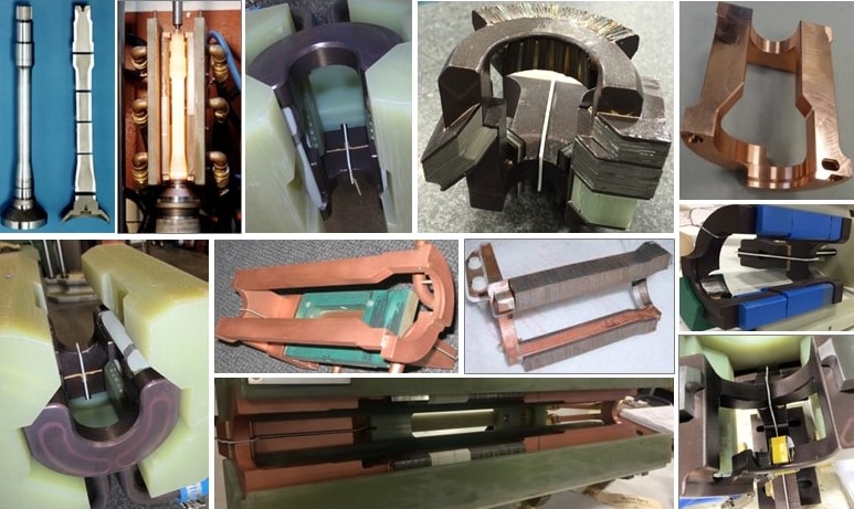
Figure 1 shows a typical shaft-like component (Figure 1,top-left) suitable for a single-shot hardening inductor, as well as a variety of traditionally designed single-shot inductors for surface hardening shaft-like workpieces. Sometimes, these inductors are also referred to as channel inductors.
A conventional single-shot inductor consists of two legs and two crossover segments, also known as bridges, “horseshoes,” or half-loops [1]. The induced eddy currents under the legs primarily flow along the length of the part (longitudinally/axially) with the exception of the regions of the workpiece located under the crossover segments where the flow of the eddy current is half circumferential. Unlike scanning inductors, traditional designs of single-shot inductors can be quite complicated.

With a predominantly longitudinal eddy current flow, the heat uniformity in the diameter change areas of the stepped shafts is dramatically improved and the tendency of corners and shoulders to be overheated is reduced significantly compared to applying a single-turn or multi-turn solenoid coils commonly used in scan hardening and continuous/progressive hardening.
Because the copper of single-shot inductors does not completely encircle the entire region required to be heated, rotation must be used to create a sufficiently uniform austenitized surface layer along the workpiece perimeter. Upon quenching, a sufficiently uniform hardness case depth along the circumference of the part will be produced. For single-shot inductors, the rotation speed usually ranges from 120 to 500 rpm.
Different types of magnetic flux concentrators (also called flux intensifiers, flux controllers, flux diverters, magnetic shunts, etc.) complement the copper profiling of an inductor, helping to achieve the required hardness pattern. Flux concentrators may provide several considerable benefits when applied in single-shot inductors. This includes an increase of coil electrical efficiency, a noticeable reduction of coil current, and a significant reduction of the external magnetic field exposure.
As an example, Figure 2 shows a transverse cross-section of a single-shot inductor and a straight shaft. Computer-modeled electromagnetic field distribution of a bare inductor (Figure 2, left) compared to an inductor with a U-shaped flux concentrator (Figure 2, right) is shown. Note that the magnitude of magnetic field intensity on both images is different. The use of U-shaped magnetic flux concentrators in single-shot hardening applications typically results in a 16% to 27% coil current reduction compared to using a bare inductor while having a similar heating effect. A reduction of the external magnetic field exposure while applying flux concentrator is even more dramatic (Figure 2, right).
![Figure 2. Computer-modeled EMF distribution in the transverse cross-section of a bare inductor (left) compared to an inductor with U-shaped flux concentrator (right). Note: the scale of magnetic field intensity on both images is different [1].](https://heattreattoday.com/wp-content/uploads/2019/08/Rudnev-Part-2-Fig-2.jpg)
- applied frequency, power density, and duty cycle;
- operating temperature and ability to be cooled;
- geometries of workpiece and inductor;
- machinability, formability, structural homogeneity, and integrity;
- an ability to withstand an aggressive working environment resisting chemical attack by quenchants and corrosion;
- brittleness, density, and ability to withstand occasional impact force;
- ease of installation and removal, available space for installation, and so on.
It should be noted that, though in most single-shot hardening applications flux concentrators will improve efficiency, there are other cases where no improvement will be recorded, or efficiency may even drop. A detailed discussion regarding the subtleties of using magnetic flux concentrators is provided in [See References 1, 2.].
Sufficient rotation is critical when using any single-shot inductor design. As an example, Figure 3 shows the sketch of a single-shot induction hardening system.
![Figure 3. Sketch of single-shot induction hardening of an axle shaft. Note: The right half of this induction system is computer-modeled in Fig. 4 [3].](https://heattreattoday.com/wp-content/uploads/2019/08/Rudnev-Part-2-Fig-3-1024x617.jpg)
![Figure 4. Results of numerical simulation of heating an axle shaft by using a single-shot inductor [3].](https://heattreattoday.com/wp-content/uploads/2019/08/Rudnev-Part-2-Fig-4.jpg)
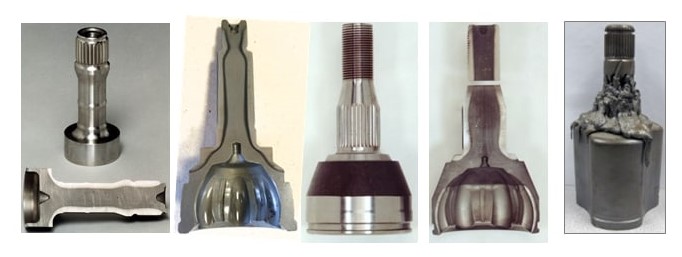
An appropriate inductor design with a closely controlled and monitored rotation speed will produce a hardness pattern with minimum circumferential and longitudinal temperature deviations, which will result in sufficiently uniform hardness patterns (Figure 5, left four images). Failure to ensure proper rotation as well as the use of worn centers (lacking grabbing force resulting in slippage and excessive part wobbling) could lead to an unacceptable heat non-uniformity, severe local overheating, and even melting (Figure 5, right). Manufacturers of induction equipment such as Inductoheat have developed various proprietary tools, holders, fixtures, and monitoring devices to ensure proper rotation and high quality of single-shot hardened parts.

The next installment of this column, "Dr. Valery Rudnev on . . . ", will continue the discussion of design features of induction single-shot hardening systems.
References
- V.Rudnev, D.Loveless, R.Cook, Handbook of Induction Heating, 2nd Edition, CRC Press, 2017.
- V.Rudnev, "An objective assessment of magnetic flux concentrators", Heat Treating Progress, ASM Intl., December 2004, pp 19-23.
- V.Rudnev, "Simulation of Induction Heat Treating", ASM Handbook, Volume 22B, Metals Process Simulation, D.U. Furrer and S.L. Semiatin, editors, ASM Int’l, 2010, pp 501-546.


